EP0274037A1 - Procédé et dispositif pour la séparation des particules - Google Patents
Procédé et dispositif pour la séparation des particules Download PDFInfo
- Publication number
- EP0274037A1 EP0274037A1 EP87117222A EP87117222A EP0274037A1 EP 0274037 A1 EP0274037 A1 EP 0274037A1 EP 87117222 A EP87117222 A EP 87117222A EP 87117222 A EP87117222 A EP 87117222A EP 0274037 A1 EP0274037 A1 EP 0274037A1
- Authority
- EP
- European Patent Office
- Prior art keywords
- steam
- mixture
- gas mixture
- carrier medium
- particles
- Prior art date
- Legal status (The legal status is an assumption and is not a legal conclusion. Google has not performed a legal analysis and makes no representation as to the accuracy of the status listed.)
- Withdrawn
Links
Images

Classifications
-
- B—PERFORMING OPERATIONS; TRANSPORTING
- B01—PHYSICAL OR CHEMICAL PROCESSES OR APPARATUS IN GENERAL
- B01D—SEPARATION
- B01D7/00—Sublimation
-
- B—PERFORMING OPERATIONS; TRANSPORTING
- B01—PHYSICAL OR CHEMICAL PROCESSES OR APPARATUS IN GENERAL
- B01D—SEPARATION
- B01D50/00—Combinations of methods or devices for separating particles from gases or vapours
- B01D50/20—Combinations of devices covered by groups B01D45/00 and B01D46/00
-
- B—PERFORMING OPERATIONS; TRANSPORTING
- B01—PHYSICAL OR CHEMICAL PROCESSES OR APPARATUS IN GENERAL
- B01D—SEPARATION
- B01D51/00—Auxiliary pretreatment of gases or vapours to be cleaned
-
- B—PERFORMING OPERATIONS; TRANSPORTING
- B01—PHYSICAL OR CHEMICAL PROCESSES OR APPARATUS IN GENERAL
- B01D—SEPARATION
- B01D53/00—Separation of gases or vapours; Recovering vapours of volatile solvents from gases; Chemical or biological purification of waste gases, e.g. engine exhaust gases, smoke, fumes, flue gases, aerosols
Definitions
- the invention is based on a method for separating particles and an apparatus for carrying out the method.
- it relates to a method for separating particles which have at least one first substance which can be evaporated below a predetermined temperature and at least one second substance which remains in particle form above the predetermined temperature, in which the particles are heated to the predetermined temperature together with a flowing gaseous carrier medium , wherein a vapor-gas mixture is formed from the at least one evaporating first substance and the gaseous carrier medium, which mixture is then at least partially cooled until the at least one evaporated first substance condenses.
- it also relates to a device for carrying out this method with a blower and a heating device connected downstream of the blower and operatively connected to a cooler.
- a discontinuous process for the separation of particles is known from the magazine “Staub, Rein temperament der Lucas", volume 46 (1986), pages 120 to 124.
- individual batches of particles for example Electro filter dust with attached heavy metal compounds, heated to comparatively high temperatures together with a flowing gaseous carrier medium. Components of these particles, in particular the heavy metal compounds, evaporate and form a vapor-gas mixture with the carrier medium.
- This steam-gas mixture is then cooled until the evaporated components condense.
- the condensate can be used for analysis purposes.
- the device which is used for this separation consists of a blower which moves the carrier medium over the particles introduced batchwise into the heating device.
- the steam-gas mixture created in the heating device is cooled in a downstream cooler.
- the invention seeks to remedy this.
- the invention as characterized in the claims, achieves the object of specifying a continuous process for separating particles which can be used on an industrial scale and to provide an apparatus for carrying out the process which enables economically advantageous, continuous operation.
- the advantages achieved by the invention are essentially to be seen in the fact that larger quantities of particles, for example filter dusts with accumulated pollutants, can be processed continuously and freed from these pollutants.
- the pollutants are collected and processed further or stored in hazardous waste landfills, while in particle form Remaining substances, for example the filter dust cleaned of pollutants, from which then no longer poses a risk to the environment, can be accommodated in ordinary landfills or used as building material.
- FIG. 1 shows the interaction of the various components that are important for the method.
- a fan 1 maintains the flow of a gaseous carrier medium. Any losses of the carrier medium can be replaced in a controlled manner via a connection 3 from a reserve container 2.
- the flow of the carrier medium leads from the blower 1 into a mixer 4, which is designed, for example, as a centrifugal or high-speed mixer.
- a mixer 4 is also the outlet 5 of a feed hopper 6 is inserted, which is filled with particles.
- the particles are mixed continuously and in metered amounts with the flowing gaseous carrier medium to form a fluidized mixture which flows into a heating device 7.
- a heating device 7 components of the particles evaporate and together with the heated carrier medium form a vapor-gas mixture.
- This steam-gas mixture leaves, together with constituents of the particles remaining in particle form, the heating device 7 as a mixture.
- the mixture is passed into a dust separator 8, in which the predominant amount of the constituents of the particles remaining in particle form are separated and through a line 9 in a dust silo 10 is guided.
- the steam-gas mixture emerging from the dust separator 8, with a small proportion of residues of the constituents of the particles remaining in particle form, is led to a branch 15.
- a first part of this steam-gas mixture is branched off and fed back through line 16 as a recycle stream to an inlet 17 of the fan 1.
- a second part of this steam-gas mixture is fed through line 18 into a hot gas filter 19 led and freed there from the remains of the constituents remaining in particle form.
- the separated residues of the constituents remaining in particle form are introduced into the dust silo 10 through a line 20.
- the steam-gas mixture is introduced after the hot gas filter 19 into a cooler 21, which can have different stages 21a, 21b with different levels of the cooling temperature.
- the vaporized constituents of the particles condense out in accordance with their specific condensation temperatures in the respective stages 21a, 21b of the cooler and are collected in assigned collectors 22a, 22b.
- the cooled carrier medium leaves the cooler 21 and is returned through a line 23 into the inlet 17 of the blower 1.
- the line 16 for the circulating stream can also be omitted or switched off if the composition of the particles allows this.
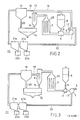
- FIG. 2 shows the device which operates in accordance with the block diagram in FIG. 1. Control, regulating and metering devices, sensors, filling, removal and shut-off devices, etc., which must necessarily be present, are not shown in this schematic illustration. Furthermore, thermal insulation, which includes the entire device except the cooler 21, has also been omitted. The connection 3 to the reserve container 2 is only hinted at.
- heating elements 25 are specified which heat the fluidized batch.
- the heating elements 25 can be heated electrically or, for example, also advantageously by means of process heat, such as occurs in a waste incineration plant, in power plants or in cement plants.
- the heating temperature can be selected and adjusted from a few 100 ° C to around 1200 ° C, depending on which constituents of the particles are to be evaporated.
- the heating device 7 is designed such that the fluidized mixture forms a fluidized bed in it. In this way it is achieved that this mixture flows through the heating device 7 in a controlled manner, so that all particles are also heated uniformly.
- the average residence time of the particles in the fluidized bed area can be adapted to the respective chemical composition of the particles.
- the dust separator 8 is advantageously designed as a single or multi-stage cyclone. No temperature gradient may occur between the heating device 7, the dust separator 8 and the hot gas filter 19, so that the evaporated constituents cannot accumulate again on the constituents remaining in particle form. After this dust collector 8 is at the junction 15 through the line 16 as a rule Weighing part of the steam-gas mixture formed in the heating device 7 is recycled as a recycle stream to the blower 1 and is fed back into the circuit there as a carrier medium. The remaining portion of the steam-gas mixture is passed through line 18 into a hot gas filter 19, which can be designed, for example, as an electrostatic filter or as a ceramic honeycomb filter.
- this hot gas filter 19 the residues of the constituents remaining in particle form are removed from the remaining portion of the steam-gas mixture.
- This steam-gas mixture is then introduced into the cooler 21 and cooled in various stages 21a, 21b.
- the levels of the cooling temperature are chosen such that a certain fraction of the steam-gas mixture condenses at each level and is discharged liquid into the respective collector 22a, 22b. Depending on the composition of the steam-gas mixture, different levels of the cooling temperature can also be set.
- the cooler 21 cools the steam-gas mixture until all relevant evaporated constituents of the particles have been condensed and removed.
- the steam-gas mixture or carrier medium emerging from the cooler 21, which still has residual heat, is returned to the blower 1, where it is fed back into the circuit.
- FIG. 3 shows a device in which, after the majority of the constituents of the particles remaining in the form of particles have been separated off, the entire vapor-gas mixture is freed from residues of the constituents of the particles remaining in the form of particles and then cooled completely.
- This device emerges from the block diagram of Fig. 1 when line 16 is omitted for the recycle stream becomes. All other elements function in the same way as in the device according to FIG. 2, but here the hot gas filter 19 and the cooler 21 must have larger dimensions or have a more powerful design if the device is loaded with equal amounts of particles. The advantage of this device can be seen in the fact that little contaminated particles can be cleaned quickly and in large quantities.
- the gaseous carrier medium may be used under normal, positive or negative pressure and at the same time to let the entire device work under the most favorable pressure conditions.
- this requires corresponding constructive precautions, e.g. pressure-tight locks at the outlet 5 of the loading hopper 6, at the outlet of the dust silo 10 and the outlets of the individual stages 21a, 21b of the filter 21.
- the entire device must be designed to be pressure-tight.
- the gaseous carrier medium can, depending on the particles to be processed, contain an oxidizing or a reducing gas or gas mixture, just as it can consist of an inert gas or gas mixture. If an oxidizing or a reducing gas is used, a possibility is advantageously provided in line 23 which allows the oxidizing or reducing gas to be regenerated. If the device according to FIG. 2 is used, such a regeneration option can possibly also be provided in line 16.
- a gas scrubber in line 23 in order to prevent pollutants which do not condense from accumulating in the device.
- the line 23 can for example wise also be routed through the gas scrubber, which is usually connected to a waste incinerator. It is also possible to pass the steam-gas mixture in line 23 into the combustion chamber of the waste incinerator in order to make the pollutants harmless there.
- Dust was removed from the filter system of a waste incineration plant with i.a. 0.2% cadmium content and 3.25% lead content in the mixer 4 mixed with the carrier medium nitrogen to form a fluidized mixture.
- the nitrogen flow was set to 0.5 m3 / h, the dust concentration was metered to 40 g / m3.
- the fluidized batch was passed through an electrically heated heating device 7 and heated there to 1000 ° C. The residence time of the batch in this heating device 7 was approximately six seconds. After the dust separator 8 and the hot gas filter 19, liquid residues were found in the cooler 21.
- the cleaned dust removed from the dust separator 8 and the hot gas filter 19 had no detectable amounts of cadmium and the lead content was less than 0.05%.
- the above exemplary embodiment clearly shows that the filter dust accumulating in a waste incineration plant is freed from harmful heavy metal deposits and can then be easily stored in landfills or used for construction purposes.
- the waste volume of such a plant to be stored in hazardous waste landfills or otherwise rendered harmless can thus be significantly reduced, which has great economic and ecological advantages.
Landscapes
- Chemical & Material Sciences (AREA)
- Chemical Kinetics & Catalysis (AREA)
- Engineering & Computer Science (AREA)
- Analytical Chemistry (AREA)
- General Chemical & Material Sciences (AREA)
- Oil, Petroleum & Natural Gas (AREA)
- Processing Of Solid Wastes (AREA)
- Electrostatic Separation (AREA)
Applications Claiming Priority (2)
| Application Number | Priority Date | Filing Date | Title |
|---|---|---|---|
| CH4916/86 | 1986-12-10 | ||
| CH491686 | 1986-12-10 |
Publications (1)
| Publication Number | Publication Date |
|---|---|
| EP0274037A1 true EP0274037A1 (fr) | 1988-07-13 |
Family
ID=4284771
Family Applications (1)
| Application Number | Title | Priority Date | Filing Date |
|---|---|---|---|
| EP87117222A Withdrawn EP0274037A1 (fr) | 1986-12-10 | 1987-11-23 | Procédé et dispositif pour la séparation des particules |
Country Status (2)
| Country | Link |
|---|---|
| US (1) | US4813978A (fr) |
| EP (1) | EP0274037A1 (fr) |
Cited By (3)
| Publication number | Priority date | Publication date | Assignee | Title |
|---|---|---|---|---|
| EP0299340B1 (fr) * | 1987-07-15 | 1992-05-27 | BBC Brown Boveri AG | Méthode pour éliminer des composés des métaux lourds provenant des poussières d'incinération d'ordures, du dépoussiérage des gaz d'échappement ou de la purification des gaz |
| EP0272465B1 (fr) * | 1986-12-10 | 1993-02-24 | BBC Brown Boveri AG | Procédé et dispositif pour la séparation et/ou réaction des particules |
| DE10011531A1 (de) * | 2000-03-13 | 2001-09-27 | Montan Tech Gmbh | Vorrichtung zur Probenahme für Gasanalysen von Koksofenrohgasen und anderen verunreinigten Gasen sowie Verfahren zur Gasanalyse dieser Gase |
Families Citing this family (6)
| Publication number | Priority date | Publication date | Assignee | Title |
|---|---|---|---|---|
| DE58903943D1 (de) * | 1988-09-05 | 1993-05-06 | Asea Brown Boveri | Verfahren zur trennung von dampffoermigen schwermetallverbindungen von einem traegergas und vorrichtung zur durchfuehrung des verfahrens. |
| US5122155A (en) * | 1990-10-11 | 1992-06-16 | Eberbach Mark A | Hernia repair apparatus and method of use |
| US5074226A (en) * | 1991-02-15 | 1991-12-24 | Field Service Associates, Inc. | Flue gas conditioning system |
| DE4120277A1 (de) * | 1991-06-19 | 1992-12-24 | Krupp Polysius Ag | Verfahren und vorrichtung zum reinigen von abgasen aus ofenanlagen |
| DE4342494C1 (de) * | 1993-12-07 | 1995-07-20 | Mannesmann Ag | Verfahren und Vorrichtung zur Ausscheidung von Schwermetallen und schwermetallhaltigen Verbindungen |
| US6974494B1 (en) | 2004-10-25 | 2005-12-13 | Karim Zahedi | Apparatus and method using an electrified filter bed for removal of pollutants from a flue gas stream |
Citations (5)
| Publication number | Priority date | Publication date | Assignee | Title |
|---|---|---|---|---|
| US2608472A (en) * | 1948-01-29 | 1952-08-26 | Stokes Machine Co | Sublimation apparatus |
| FR1140652A (fr) * | 1955-02-08 | 1957-08-05 | Bayer Ag | Procédé de sublimation en couche tourbillonnante |
| GB1110649A (en) * | 1967-04-20 | 1968-04-24 | Mobil Oil Corp | Acid purification process |
| US4215101A (en) * | 1978-06-13 | 1980-07-29 | Fried. Krupp Gesellschaft Mit Beschrankter Haftung | Method and apparatus for performing chemical and/or physical treatments |
| DE3514471A1 (de) * | 1985-04-22 | 1986-10-23 | Klöckner-Humboldt-Deutz AG, 5000 Köln | Verfahren und vorrichtung zur abtrennung von arsen aus bei der metallurgischen verarbeitung von arsenhaltigen materialien in schmelzprozessen anfallenden heissem abgas |
Family Cites Families (14)
| Publication number | Priority date | Publication date | Assignee | Title |
|---|---|---|---|---|
| US2002860A (en) * | 1932-06-30 | 1935-05-28 | Levy Stanley Isaac | Treatment of iron pyrites for recovery of sulphur and formation of iron oxide |
| US2675889A (en) * | 1949-04-01 | 1954-04-20 | Schweizerhall Saeurefab | Method for processing crude gases obtained on halogenating metallic ores |
| US2771158A (en) * | 1953-06-30 | 1956-11-20 | Cabot Godfrey L Inc | Recovery of pigments from aerosols |
| US2966232A (en) * | 1958-05-02 | 1960-12-27 | Phillips Petroleum Co | Process and apparatus for separating finely divided solids from fluids |
| US3179497A (en) * | 1961-04-17 | 1965-04-20 | Yanagase Kenjiro | Production of selenium oxide, tellurium oxide or mixture thereof |
| GB1119432A (en) * | 1965-01-30 | 1968-07-10 | Mitsubishi Heavy Ind Ltd | Gas-powder contact process and apparatus therefor |
| US3395512A (en) * | 1966-03-21 | 1968-08-06 | Universal Oil Prod Co | Method and means for cooling and cleaning hot converter gases |
| SE373114B (fr) * | 1973-05-02 | 1975-01-27 | Boliden Ab | |
| DE2403282A1 (de) * | 1974-01-24 | 1975-11-06 | Metallgesellschaft Ag | Verfahren zur abscheidung von fluorwasserstoff aus abgasen der aluminiumelektrolyse durch trockenadsorption an aluminiumoxid unter vollstaendiger abtrennung der schaedlichen begleitelemente |
| GB1429427A (en) * | 1974-07-25 | 1976-03-24 | Asahi Fibreglass Co | Method of cleaning waste gases containing a fluorine component |
| DE3041010A1 (de) * | 1980-10-31 | 1982-05-27 | Kloeckner Werke Ag | Verfahren und vorrichtung zum reinigen des bei stahl- bzw. eisenbadreaktoren anfallenden kohlengases |
| DE3423798A1 (de) * | 1984-06-28 | 1986-01-09 | Bergwerksverband Gmbh, 4300 Essen | Verfahren zur auftrennung des beim verkokungsprozess anfallenden wassers in eine kleine salzreiche und eine grosse salzarme fraktion |
| US4662899A (en) * | 1985-04-05 | 1987-05-05 | American Environmental International Inc. | Air pollution control system method and apparatus |
| US4696679A (en) * | 1985-10-23 | 1987-09-29 | Foster Wheeler Usa Corporation | Method for cleaning gas produced from solid carbonaceous material in a two-stage gas producer |
-
1987
- 1987-11-23 EP EP87117222A patent/EP0274037A1/fr not_active Withdrawn
- 1987-12-03 US US07/128,272 patent/US4813978A/en not_active Expired - Fee Related
Patent Citations (5)
| Publication number | Priority date | Publication date | Assignee | Title |
|---|---|---|---|---|
| US2608472A (en) * | 1948-01-29 | 1952-08-26 | Stokes Machine Co | Sublimation apparatus |
| FR1140652A (fr) * | 1955-02-08 | 1957-08-05 | Bayer Ag | Procédé de sublimation en couche tourbillonnante |
| GB1110649A (en) * | 1967-04-20 | 1968-04-24 | Mobil Oil Corp | Acid purification process |
| US4215101A (en) * | 1978-06-13 | 1980-07-29 | Fried. Krupp Gesellschaft Mit Beschrankter Haftung | Method and apparatus for performing chemical and/or physical treatments |
| DE3514471A1 (de) * | 1985-04-22 | 1986-10-23 | Klöckner-Humboldt-Deutz AG, 5000 Köln | Verfahren und vorrichtung zur abtrennung von arsen aus bei der metallurgischen verarbeitung von arsenhaltigen materialien in schmelzprozessen anfallenden heissem abgas |
Cited By (3)
| Publication number | Priority date | Publication date | Assignee | Title |
|---|---|---|---|---|
| EP0272465B1 (fr) * | 1986-12-10 | 1993-02-24 | BBC Brown Boveri AG | Procédé et dispositif pour la séparation et/ou réaction des particules |
| EP0299340B1 (fr) * | 1987-07-15 | 1992-05-27 | BBC Brown Boveri AG | Méthode pour éliminer des composés des métaux lourds provenant des poussières d'incinération d'ordures, du dépoussiérage des gaz d'échappement ou de la purification des gaz |
| DE10011531A1 (de) * | 2000-03-13 | 2001-09-27 | Montan Tech Gmbh | Vorrichtung zur Probenahme für Gasanalysen von Koksofenrohgasen und anderen verunreinigten Gasen sowie Verfahren zur Gasanalyse dieser Gase |
Also Published As
| Publication number | Publication date |
|---|---|
| US4813978A (en) | 1989-03-21 |
Similar Documents
| Publication | Publication Date | Title |
|---|---|---|
| DE4120277A1 (de) | Verfahren und vorrichtung zum reinigen von abgasen aus ofenanlagen | |
| DE2928693A1 (de) | Abfallverarbeitungsanlage | |
| EP0461695A1 (fr) | Procédé et appareil pour la purification d'effluents de gaz poussiéreux et nocifs | |
| EP0253079B1 (fr) | Procédé et installation de traitement de sols contaminés et matières analogues | |
| EP0819233A1 (fr) | Procede et dispositif de traitement thermique de dechets | |
| EP2437866B1 (fr) | Procédé et installation pour le retrait du mercure présent dans les gaz d échappement d un processus de fabrication de ciment | |
| DE69213397T2 (de) | Verfahren und Vorrichtung zur Sanierung von Material das mit Kohlenwasserstoffen verunreinigt ist | |
| WO1989012609A1 (fr) | Procede et dispositif de traitement de scories de fours d'incineration de dechets | |
| WO1994013592A1 (fr) | Procede et installation de traitement de boues | |
| EP0359931A1 (fr) | Procédé et dispositif de séparation de composants de métaux lourds à l'état vapeur à partir d'un gaz support | |
| DE2420639A1 (de) | Verfahren zur selektiven reinigung von heissgasen | |
| DD286295A5 (de) | Verfahren und vorrichtung zur aufarbeitung kontaminierter boeden | |
| DE3703706C2 (de) | Verfahren und Anordnung zum Reinigen eines kontaminierten Heissgasstromes | |
| EP0228111B2 (fr) | Procédé pour l'élimination des substances nocives dans des gaz d'échappement | |
| DE3247228C2 (de) | Verfahren zur Rückgewinnung von unverbrannter Kohle aus Kohlenasche | |
| EP0324454B1 (fr) | Procédé et dispositif pour la purification des gaz de fumée | |
| EP0373577B1 (fr) | Procédé de traitement de boues d'épuration ou de boues industrielles à parties organiques par le procédé de conversion | |
| DE3047060C2 (de) | Verfahren und Vorrichtung zum Trocknen und Verbrennen von Schlamm | |
| EP0418847B1 (fr) | Installation pour traiter une bouillie de filtration se composant principalement de terres de diatomées et procédé de fonctionnement de l'installation | |
| DE3048764C2 (de) | Vorrichtung zum Entfernen radioaktiver Feststoffteilchen aus Naßgas | |
| EP0272465B1 (fr) | Procédé et dispositif pour la séparation et/ou réaction des particules | |
| CH683324A5 (de) | Verfahren zur thermischen Entsorgung von Reststoffen aus der Rauchgasreinigung. | |
| DD249857A5 (de) | Verfahren zur verminderung des schadstoffgehaltes von staubhaltigen rauch- oder prozessgasen | |
| EP3021955B1 (fr) | Méthode et appareil pour purifier des gaz effluents | |
| EP0305584A2 (fr) | Procédé de traitement des gaz d'échappement, en particulier pour leur neutralisation |
Legal Events
| Date | Code | Title | Description |
|---|---|---|---|
| PUAI | Public reference made under article 153(3) epc to a published international application that has entered the european phase |
Free format text: ORIGINAL CODE: 0009012 |
|
| AK | Designated contracting states |
Kind code of ref document: A1 Designated state(s): AT CH DE FR GB IT LI SE |
|
| 17P | Request for examination filed |
Effective date: 19881212 |
|
| 17Q | First examination report despatched |
Effective date: 19900713 |
|
| STAA | Information on the status of an ep patent application or granted ep patent |
Free format text: STATUS: THE APPLICATION IS DEEMED TO BE WITHDRAWN |
|
| 18D | Application deemed to be withdrawn |
Effective date: 19910717 |
|
| RIN1 | Information on inventor provided before grant (corrected) |
Inventor name: WIEGART, NORBERT, DR. Inventor name: HIRTH, MICHAEL, DR. |