EP0274073A2 - Doppelt balancierter Mischer - Google Patents
Doppelt balancierter Mischer Download PDFInfo
- Publication number
- EP0274073A2 EP0274073A2 EP87118253A EP87118253A EP0274073A2 EP 0274073 A2 EP0274073 A2 EP 0274073A2 EP 87118253 A EP87118253 A EP 87118253A EP 87118253 A EP87118253 A EP 87118253A EP 0274073 A2 EP0274073 A2 EP 0274073A2
- Authority
- EP
- European Patent Office
- Prior art keywords
- lines
- access
- coplanar
- mixer
- line
- Prior art date
- Legal status (The legal status is an assumption and is not a legal conclusion. Google has not performed a legal analysis and makes no representation as to the accuracy of the status listed.)
- Granted
Links
Images


Classifications
-
- H—ELECTRICITY
- H03—ELECTRONIC CIRCUITRY
- H03D—DEMODULATION OR TRANSFERENCE OF MODULATION FROM ONE CARRIER TO ANOTHER
- H03D9/00—Demodulation or transference of modulation of modulated electromagnetic waves
- H03D9/06—Transference of modulation using distributed inductance and capacitance
- H03D9/0608—Transference of modulation using distributed inductance and capacitance by means of diodes
- H03D9/0633—Transference of modulation using distributed inductance and capacitance by means of diodes mounted on a stripline circuit
-
- H—ELECTRICITY
- H01—ELECTRIC ELEMENTS
- H01P—WAVEGUIDES; RESONATORS, LINES, OR OTHER DEVICES OF THE WAVEGUIDE TYPE
- H01P5/00—Coupling devices of the waveguide type
- H01P5/12—Coupling devices having more than two ports
- H01P5/16—Conjugate devices, i.e. devices having at least one port decoupled from one other port
- H01P5/19—Conjugate devices, i.e. devices having at least one port decoupled from one other port of the junction type
- H01P5/20—Magic-T junctions
-
- H—ELECTRICITY
- H03—ELECTRONIC CIRCUITRY
- H03D—DEMODULATION OR TRANSFERENCE OF MODULATION FROM ONE CARRIER TO ANOTHER
- H03D2200/00—Indexing scheme relating to details of demodulation or transference of modulation from one carrier to another covered by H03D
- H03D2200/0001—Circuit elements of demodulators
- H03D2200/0023—Balun circuits
-
- H—ELECTRICITY
- H03—ELECTRONIC CIRCUITRY
- H03D—DEMODULATION OR TRANSFERENCE OF MODULATION FROM ONE CARRIER TO ANOTHER
- H03D7/00—Transference of modulation from one carrier to another, e.g. frequency-changing
- H03D7/14—Balanced arrangements
- H03D7/1408—Balanced arrangements with diodes
Definitions
- the present invention relates to a doubly balanced mixing device.
- the mixing devices make it possible, from a first signal of given frequency, to obtain by beating with a second signal of different frequency, delivered by a local oscillator, a certain number of signals of different frequencies, in particular of a signal with an intermediate frequency equal to the difference of the two above-mentioned frequencies.
- a doubly balanced mixer allows, using couplers and phase shifters, to have a natural insulation between the signal, local oscillator and intermediate frequency gates.
- many combinations of parasitic frequencies are strongly attenuated towards the intermediate frequency gate.
- the known devices of the prior art have a significant limitation in frequency bandwidth on one of the ports, generally on the intermediate frequency port.
- the various doors are loaded by parasitic elements dimensioned by the other doors.
- the adaptation circuits are not independent, which prohibits certain overlaps between the different bands.
- the devices of the known art require special machining of the circuit substrate.
- the object of the present invention is to overcome these drawbacks.
- the invention provides a doubly balanced mixing device comprising four elementary mixers and three accesses, characterized in that phase-shifters, making it possible to achieve a phase shift of ⁇ + k ⁇ , (k being an integer), are respectively arranged between the first mixer and the first and third ports; between the second mixer and the second and third ports; between the third mixer and the first port; and between the fourth mixer and the second port.
- the invention thus makes it possible to avoid the particular machining of the substrate which is due in the prior art to the use of the two faces of the latter, and to present very wide bands on the three accesses; for example, two octaves of frequency arbitrarily chosen in the band 2-26 GHz, for the signal and the intermediate frequency, and 1-26 GHz for the local oscillator.
- phase differences ⁇ are produced by means of phase shifters 38, 39, 40, 41, 42 and 43; They are indicated to the nearest k ⁇ (whole k).
- the angular value ⁇ is not limiting; it can indeed be tainted with error.
- phase shifters are respectively arranged between the first mixer (10) and the first (14) and the third (16) access (38 and 39); between the second mixer (11) and the second (15) and the third (16) access (40 and 41); between the third mixer (12) and the first (14) port (42); and between the fourth mixer (13) and the second (15) port (43).
- - radio frequency or FR
- - intermediate frequency or IF
- - local oscillator or OL
- phase oppositions thus defined make it possible to obtain the suppression of certain lines, and thus to weaken the parasitic frequencies at the output.
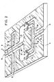
- the two embodiments of Figures 2 and 3, according to the invention, use two dielectric supports, or substrate 5 and 6 on the upper face of which are deposited thin or thick conductive films, in the form of slit lines and coplanar lines.
- a slotted line propagates an asymmetric mode; a coplanar line, a symmetrical mode and an anti-asymmetric mode.
- the transverse electric field is symmetrical with respect to the axis of propagation.
- the access 14 excites a coplanar line 9 in symmetrical mode and the access 15 excites a coplanar line 17 in symmetrical mode, which excites a coplanar line 18, located in the extension of line 9, in asymmetric mode .
- a metallic ribbon 8 which forms a short circuit for the asymmetric mode, allows the return of all the energy from line 17 to line 18.
- a transition between lines 17 and 18 is carried out using a metal strip 19 and a coplanar line in ⁇ / 4 20, the strip 19 making the connection with the central conductor 7 of the line 20.
- the coplanar line 18 is divided into two slot lines 21 and 22.
- this line 18 is divided into two coplanar lines in symmetrical mode 23 and 24.
- the lateral conductors of lines 21 and 22 are connected to diodes 10, 11, 12 and 13.
- the access 16 excites a coplanar line 25 in symmetrical mode which is divided into two coplanar lines 28 and 29 with symmetrical propagation whose central conductors 32 and 33 are respectively connected to the common points of the diodes 12 and 13 and 10 and 11.
- the two first diodes 10 and 11 are arranged in the direction passing from the lateral conductors to the central conductor 33; The other two diodes 12 and 13 in the other direction.
- the access 16 excites a same coplanar line 25 in symmetrical mode which is divided, this time, into two slotted lines 26 and 27 whose lateral conductors are connected to the diodes 12, 13, 10 and 11. These diodes all have the same passing direction.
- the diodes 10, 11, 12, 13, or elementary mixers are fixed to the surface of the substrate, for example by soldering, gluing ...
- the Signal (RF), intermediate frequency (IF) and local oscillator (OL) accesses can be swapped, the diode mounting direction can be changed.
- the frequency IF can be a combination of a harmonic of the frequency OL and the frequency RF or of the frequency OL and the frequency RF.
- the elementary mixers can be connected by capacities, inductors, or lines coupled to the surrounding conductors and can be polarized in direct current. Conductor areas can be isolated, in direct current, from the surrounding conductors.
- Conductive surfaces can be removed.
Landscapes
- Physics & Mathematics (AREA)
- Electromagnetism (AREA)
- Engineering & Computer Science (AREA)
- Power Engineering (AREA)
- Inductance-Capacitance Distribution Constants And Capacitance-Resistance Oscillators (AREA)
- Transceivers (AREA)
Applications Claiming Priority (2)
| Application Number | Priority Date | Filing Date | Title |
|---|---|---|---|
| FR8617359A FR2608324B1 (fr) | 1986-12-11 | 1986-12-11 | Dispositif melangeur doublement equilibre |
| FR8617359 | 1986-12-11 |
Publications (3)
| Publication Number | Publication Date |
|---|---|
| EP0274073A2 true EP0274073A2 (de) | 1988-07-13 |
| EP0274073A3 EP0274073A3 (en) | 1988-07-27 |
| EP0274073B1 EP0274073B1 (de) | 1992-05-20 |
Family
ID=9341796
Family Applications (1)
| Application Number | Title | Priority Date | Filing Date |
|---|---|---|---|
| EP19870118253 Expired - Lifetime EP0274073B1 (de) | 1986-12-11 | 1987-12-09 | Doppelt balancierter Mischer |
Country Status (3)
| Country | Link |
|---|---|
| EP (1) | EP0274073B1 (de) |
| DE (1) | DE3779285D1 (de) |
| FR (1) | FR2608324B1 (de) |
Cited By (2)
| Publication number | Priority date | Publication date | Assignee | Title |
|---|---|---|---|---|
| AU616612B2 (en) * | 1989-09-15 | 1991-10-31 | Hughes Aircraft Company | Planar airstripline-stripline magic-tee |
| AU634348B2 (en) * | 1990-02-21 | 1993-02-18 | Siemens Telecomunicazioni S.P.A. | Image rejection frequency converter provided in planar technology |
Family Cites Families (2)
| Publication number | Priority date | Publication date | Assignee | Title |
|---|---|---|---|---|
| JPS5535530A (en) * | 1978-09-06 | 1980-03-12 | Nippon Telegr & Teleph Corp <Ntt> | Mic double balance type mixer |
| JPS60172803A (ja) * | 1984-02-17 | 1985-09-06 | Nippon Telegr & Teleph Corp <Ntt> | 共平面マジツクt |
-
1986
- 1986-12-11 FR FR8617359A patent/FR2608324B1/fr not_active Expired
-
1987
- 1987-12-09 EP EP19870118253 patent/EP0274073B1/de not_active Expired - Lifetime
- 1987-12-09 DE DE8787118253T patent/DE3779285D1/de not_active Expired - Fee Related
Cited By (2)
| Publication number | Priority date | Publication date | Assignee | Title |
|---|---|---|---|---|
| AU616612B2 (en) * | 1989-09-15 | 1991-10-31 | Hughes Aircraft Company | Planar airstripline-stripline magic-tee |
| AU634348B2 (en) * | 1990-02-21 | 1993-02-18 | Siemens Telecomunicazioni S.P.A. | Image rejection frequency converter provided in planar technology |
Also Published As
| Publication number | Publication date |
|---|---|
| DE3779285D1 (de) | 1992-06-25 |
| EP0274073B1 (de) | 1992-05-20 |
| FR2608324A1 (fr) | 1988-06-17 |
| FR2608324B1 (fr) | 1989-03-24 |
| EP0274073A3 (en) | 1988-07-27 |
Similar Documents
| Publication | Publication Date | Title |
|---|---|---|
| EP0013222B1 (de) | Diodenphasenschieber für Mikrowellen und elektronisch abtastende Antenne mit einem solchen Schieber | |
| EP0078187B1 (de) | Hochfrequenz-subharmonische-Mischanordnung und deren Verwendung in einem H.F.-Frequenzumsetzer | |
| FR2482384A1 (fr) | Dispositif de combinaison de puissance pour un circuit integre hyperfrequence | |
| EP0014620A1 (de) | Mikrowellenschaltung mit gekoppelten Koplanarleitungen und Vorrichtung mit einer solchen Schaltung | |
| EP0047686B1 (de) | Hybrider Mikrowellenmischer | |
| FR2461368A1 (fr) | Dispositif a ondes magnetostatiques comportant une structure d'echange a bandes conductrices | |
| EP0387955A1 (de) | Gehäuse für eine integrierte Hyperfrequenzschaltung | |
| FR2535905A1 (fr) | Circuit de couplage a haute frequence notamment pour double amplificateur equilibre | |
| FR2862158A1 (fr) | Balun distribue a rapport d'impedance non unitaire | |
| EP0274073B1 (de) | Doppelt balancierter Mischer | |
| EP0078188B1 (de) | Breitband-Hochfrequenzanordnung zur Erzeugung von harmonischer gerader Ordnung eines Eingangssignals und deren Verwendung in einem H.F.-System | |
| EP0335788B1 (de) | Mikrowellenphasenschieber | |
| EP1234356A1 (de) | Aktiver hf reflektor unter verwendung von elektronischer strahlschenkung | |
| FR2812457A1 (fr) | Reflecteur hyperfrequence actif a bi-polarisation, notamment pour antenne a balalyage electronique | |
| EP0005403A1 (de) | In Einzelmode arbeitender, durch Änderung eines magnetischen Feldes abstimmbarer Hyperfrequenz-Oszillator | |
| EP0038260B1 (de) | Magnetostatische Volumenwelleneinrichtung | |
| EP0097075B1 (de) | Ultrahochfrequenz-Mischer für elektromagnetische Wellen | |
| US4627104A (en) | Mixer | |
| EP0983616B1 (de) | Verfahren und vorrichtung zum verbinden zweier millimeterelemente | |
| FR2668304A1 (fr) | Dephaseur reciproque en guide dielectrique a ferrite. | |
| EP0296929B1 (de) | Symmetrische Mikrowellenübertragungsleitung mit zwei koplanären Leitern | |
| EP0102888B1 (de) | Mischer für elektromagnetische Wellen, ultrahoher Frequenz mit Rückgewinnung der Summenfrequenzleistung | |
| FR2508256A1 (fr) | Convertisseur de frequence equilibre double simplifie | |
| FR2496997A1 (fr) | Dispositif de reglage de l'accord d'une ligne de transmission resonnante, ligne de transmission et filtre de bande hyperfrequence munis de tels dispositifs. | |
| FR2662308A1 (fr) | Dispositif de transition entre deux lignes hyperfrequence realisees en technologie planaire. |
Legal Events
| Date | Code | Title | Description |
|---|---|---|---|
| PUAI | Public reference made under article 153(3) epc to a published international application that has entered the european phase |
Free format text: ORIGINAL CODE: 0009012 |
|
| PUAL | Search report despatched |
Free format text: ORIGINAL CODE: 0009013 |
|
| AK | Designated contracting states |
Kind code of ref document: A2 Designated state(s): DE FR GB IT SE |
|
| AK | Designated contracting states |
Kind code of ref document: A3 Designated state(s): DE FR GB IT SE |
|
| 17P | Request for examination filed |
Effective date: 19890118 |
|
| 17Q | First examination report despatched |
Effective date: 19910110 |
|
| GRAA | (expected) grant |
Free format text: ORIGINAL CODE: 0009210 |
|
| AK | Designated contracting states |
Kind code of ref document: B1 Designated state(s): DE FR GB IT SE |
|
| REF | Corresponds to: |
Ref document number: 3779285 Country of ref document: DE Date of ref document: 19920625 |
|
| GBT | Gb: translation of ep patent filed (gb section 77(6)(a)/1977) | ||
| ITF | It: translation for a ep patent filed | ||
| PLBE | No opposition filed within time limit |
Free format text: ORIGINAL CODE: 0009261 |
|
| STAA | Information on the status of an ep patent application or granted ep patent |
Free format text: STATUS: NO OPPOSITION FILED WITHIN TIME LIMIT |
|
| 26N | No opposition filed | ||
| PGFP | Annual fee paid to national office [announced via postgrant information from national office to epo] |
Ref country code: SE Payment date: 19940922 Year of fee payment: 8 |
|
| PGFP | Annual fee paid to national office [announced via postgrant information from national office to epo] |
Ref country code: FR Payment date: 19940929 Year of fee payment: 8 |
|
| PGFP | Annual fee paid to national office [announced via postgrant information from national office to epo] |
Ref country code: DE Payment date: 19940930 Year of fee payment: 8 |
|
| PGFP | Annual fee paid to national office [announced via postgrant information from national office to epo] |
Ref country code: GB Payment date: 19941024 Year of fee payment: 8 |
|
| EAL | Se: european patent in force in sweden |
Ref document number: 87118253.1 |
|
| PG25 | Lapsed in a contracting state [announced via postgrant information from national office to epo] |
Ref country code: GB Effective date: 19951209 |
|
| PG25 | Lapsed in a contracting state [announced via postgrant information from national office to epo] |
Ref country code: SE Effective date: 19951210 |
|
| GBPC | Gb: european patent ceased through non-payment of renewal fee |
Effective date: 19951209 |
|
| PG25 | Lapsed in a contracting state [announced via postgrant information from national office to epo] |
Ref country code: FR Effective date: 19960830 |
|
| PG25 | Lapsed in a contracting state [announced via postgrant information from national office to epo] |
Ref country code: DE Effective date: 19960903 |
|
| REG | Reference to a national code |
Ref country code: FR Ref legal event code: ST |
|
| PG25 | Lapsed in a contracting state [announced via postgrant information from national office to epo] |
Ref country code: IT Free format text: LAPSE BECAUSE OF NON-PAYMENT OF DUE FEES;WARNING: LAPSES OF ITALIAN PATENTS WITH EFFECTIVE DATE BEFORE 2007 MAY HAVE OCCURRED AT ANY TIME BEFORE 2007. THE CORRECT EFFECTIVE DATE MAY BE DIFFERENT FROM THE ONE RECORDED. Effective date: 20051209 |