EP0274077A1 - Thermische Messeinrichtung - Google Patents
Thermische Messeinrichtung Download PDFInfo
- Publication number
- EP0274077A1 EP0274077A1 EP87118312A EP87118312A EP0274077A1 EP 0274077 A1 EP0274077 A1 EP 0274077A1 EP 87118312 A EP87118312 A EP 87118312A EP 87118312 A EP87118312 A EP 87118312A EP 0274077 A1 EP0274077 A1 EP 0274077A1
- Authority
- EP
- European Patent Office
- Prior art keywords
- temperature
- sensing system
- transducer
- accordance
- heat
- Prior art date
- Legal status (The legal status is an assumption and is not a legal conclusion. Google has not performed a legal analysis and makes no representation as to the accuracy of the status listed.)
- Granted
Links
Images




Classifications
-
- F—MECHANICAL ENGINEERING; LIGHTING; HEATING; WEAPONS; BLASTING
- F24—HEATING; RANGES; VENTILATING
- F24F—AIR-CONDITIONING; AIR-HUMIDIFICATION; VENTILATION; USE OF AIR CURRENTS FOR SCREENING
- F24F11/00—Control or safety arrangements
-
- G—PHYSICS
- G01—MEASURING; TESTING
- G01W—METEOROLOGY
- G01W1/00—Meteorology
- G01W1/17—Catathermometers for measuring "cooling value" related either to weather conditions or to comfort of other human environment
-
- G—PHYSICS
- G05—CONTROLLING; REGULATING
- G05D—SYSTEMS FOR CONTROLLING OR REGULATING NON-ELECTRIC VARIABLES
- G05D23/00—Control of temperature
- G05D23/19—Control of temperature characterised by the use of electric means
Definitions
- the present invention relates to a thermal sensing system for sensing thermal condition, including effects of radiant heat and air flow, of environments for air conditioning system, and is for use for providing comfortable environment for human being.
- Air conditioning system to provide comfortable indoor environment for human being conventionally has been controlled mostly based on results of measurement of only environmental air temperature by temperature sensor, such as principally, thermistor.
- temperature sensor such as principally, thermistor.
- the air temperature since the air temperature only has been directly detected and the controlling is made thereby, it has not been possible to reflect human sensations concerning air flow and radiation temperature, which are also fundamental items for human sensation besides the air temperature for human sensation of comfortability. Accordingly, even though the air temperature is maintained constant the temperature sensation to be felt by human body differs depending on various environmental conditions, and therefore the controlling becomes sometimes too hot or too cold and the user must change the temperature setting time by time even though a thermostat is used.
- Human body retains its body temperature substantially constant in order to keep its life activity good. That is it produces heat by metabolism in the body, and on the other hand makes thermal exchange with environment principally by convection, radiation and evaporation, thereby to keep temperature of deep inside part of the the body constant. For a instance, generation of cool feeling at receiving wind is induced by heat loss through convection, and producing of warm feeling under strong sunshine from clear sky, even under moderate environmental temperature is caused by reception of solar radiation by the human body. Besides, the body temperature adjustment is made by controlling of blood flow, sweating under hot condition and shivering at a cold condition. The thermal sensation of human body becomes worse as extent of temperature adjustment required for the human body increases, such as by increased controlling of blood flow, sweating and shivering.
- the human thermal sensation has a correlation with human skin temperature, which is junction point between the human body and the environment. Accordingly, if there is provided a thermal sensing system which produces a heat analogous to the human skin and at the same time senses the environmental condition, the thermal sensation of the human body can be simulated thereby.
- Average condition of convection heat transfer of the whole human body can be considered to be substantially equivalent to and be simulated by a transducer of a size of cylinder of about 15 cm diameter or a sphere of about 15 cm diameter. Therefore, by heating such transducer to a temperature which is substantially equal to that of the human body and by measuring its surface temperature, a good simulation system of thermal sensing can be realized. In such way, various trials have been made.
- a transducer of a size of cylinder of about 15 cm diameter or a sphere of about 15 cm diameter. Therefore, by heating such transducer to a temperature which is substantially equal to that of the human body and by measuring its surface temperature, a good simulation system of thermal sensing can be realized. In such way, various trials have been made.
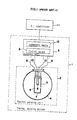
- FIG. 1 One conventional example disclosed in Japanese examined published patent application sho 35-7794 is shown in FIG. 1.
- the thermal sensing system 1 consists of a thermal sensing unit 2 and a control unit 3.
- the thermal sensing unit 2 comprises an outer shell 4 of about a size of human head skull and a temperature sensor 7 disposed therein and consisting of an electric resistor 5 as a heater connected through feed wires 8 to the control unit 3 and a temperature sensor 6 such as thermistor.
- the control unit 3 comprises controlling means 9 which is a constant voltage circuit for feeding power corresponding to heat loss amount of the human body through power feed wires 8 connected to the heater 5, and comprises ajudgement unit 12.
- the judgement unit 12 detects internal temperature change of the transducer 7 determined by environmental temperature and cooling effect influenced by air flow and radiant heat on the thermal sensing unit 2 through signal wires 10, thereby to produce control signal to the air conditioner 11 basing on difference from a preset reference value.
- thermal sensing system 2 though it is possible to output equivalent output to human thermal sensation, location or disposing thereof is limited due to its large size, and besides its power consumption is considerably large such as 10 W because it requires heat to warm large outer shell 4, and further its response time is as slow as 10--15 minutes because of its size. And accordingly such system has difficulty in practical usage for thermal sensing system for application to controlling system of an air conditioner.
- a heater 13 has a coating 14 of a jelly type material which makes temperature conductivity agree to that of human skin, and the jellied coating 14 therein has a temperature sensor 15, which is a thermocouple for sensing temperature, thereby to constitute a temperature sensor 16.
- a cover 18 which is molded by transparent polyethylene resin or the like resin which can pass heat radiation and has a number of vents.
- the cover 18 attenuates only convection heat transfer, not attenuating the radiation heat transfer, and hence equivalent output to the human thermal sensation is obtainable.
- it in order to prevent radiation heat transfer by the cover 18, it must be very thin such as of microns thickness, and there is a shortcoming that if the cover 18 is made thick in order to strengthen its structure, the radiation heat transfer unexpectedly attenuates, thereby attenuating feeling to produce equivalent radiation characteristic to the human skin.
- a special jellied material is used as the coating 14, its configuration becomes complicated, and response characteristic becomes worse.
- the present invention proposes an improved thermal sensing system capable of having equivalent sensation to convection, radiation and evaporation to that of human skin even by its small size.
- the improvement is made by adoption of special configuration to reduce flow rate of air to reduce convection heat transfer and by converging radiant heat to increase amount of radiant heat input to the transducer.
- the thermal sensing system in accordance with the present invention comprises a shell having a hollow space which has a single opening on one side and an inside face of good reflectivity for light and heat, a transducer which is disposed in the hollow space, changes electric resistance as temperature changes and makes heat by being fed electric power thereto, control means for retaining the transducer at a predetermined temperature by controlling said electric power, and judgement means for judging environmental thermal condition basing on electric power fed to the transducer from the control means.
- the system can control the air conditioning system with good response and with moderate power by using control signal suitable for microprocessor controlling. And therefore, in comparison with the conventional controlling of the air conditioning system using only air temperature sensing, more improved controlling which is agreeable to human sensation to enable comfortable environment is obtainable, through more rapid warm up or cool down of the space to be air conditioned, taking account of corrections for radiation of sun light, influence of air flow and evaporation, by using only small sized sensor unit.
- the transducer carries out exchange of radiant heat in the inside space of the shell through the opening with the ambient matters and sun shine, and besides it makes convective heat exchange with secondary flow in the inside space of the shell induced by the ambient flow. Since the shape and size of the shell is designed so that ratios among the convective heat transfer and radiant heat transfer by the transducer and ambient atmosphere is substantially identical to the case of the human body, an amount of load for retaining the transducer at a preset temperature by the controlling means corresponds to a load for retaining human body temperature at a constant value. Therefore, by taking out an electric signal corresponding to the former load, the thermal sensation of the human body can be judged through the output; and by controlling the air conditioning system basing on the output, making a comfortable air-conditioned space is easily obtainable.
- response time to changes of plural physical amounts in the environment such as air temperature, air flow and radiation temperature
- response time to changes of plural physical amounts in the environment such as air temperature, air flow and radiation temperature
- comfortable control of air conditioning system can be made by quick responding to the atmospheric change, besides the responses to plural physical amounts.
- the transducer can be designed to operate with very small wattage of power such as 3 mW, contrasted to 10 W of the conventional temperature sensing unit, the transducer can be operated by dry battery. Accordingly the transducer or temperature sensor can be enclosed in a remote control unit which is to be used near human body, or the like actual positions which are object of the control, and thereby atmospheric temperature sensing in actual situation becomes easy and ideal.
- the temperature sensing system in accordance with the present invention issues output in electric power changes which is easily usable as control signal for air conditioning system, and therefore, the sensing system has very wide utility as the thermal sensing system for the air conditioning system.
- FIG. 3 shows the whole circuit block diagram of the thermal sensing system 19 in accordance with the present invention and an air conditioner 11 which is to be controlled by the thermal sensing system 19.
- the thermal sensing system comprises a thermal sensing unit 20, configuration of which is shown inFIG. 4, and a control unit which is an electronic circuit or a microprocessor and outputs signals to control the air conditioner 11.
- the control unit 25 comprises a control part 26 and judgement part 28.
- the control part 26 controls, through electric wires 27, a transducer 24, e.g. a thermistor or a combination of a very small heater and a temperature sensing device and further gives signal to the judgement part 28.
- the judgement means judges the signal from the control part 26 and issues appropriate control signal the air conditioner 11. As shown in FIG.
- the thermal sensing unit 20 comprises a shell 22 of a cup-shape or a cylindrical shape having a wide opening 23 at its top part.
- the size of the cylindrical shape shell is, for instance of about 30 mm diameter and about 15 mm height and has inside face made of good reflective material such as aluminum to light and radiant heat.
- a small sized transducer 24, such as a thermistor is provided.
- the transducer 24 has a function to be heated by receiving a control current from the control part 26 of the control unit 25, and also changes its electric resistance depending on its temperature, to give electric signal to represent the temperature, for a instance as voltage across its both ends.
- the transducer 24 is controlled to have a temperature substantially equivalent to that of human body skin. Therefore, by receiving the signal of temperature from the transducer 24, the judgement part 28 issues a control signal for the air conditioner 11.
- the control signal corresponds to state of control load of the control part 26, such as voltage across two lead wires 27, or current therethrough, taking account of human temperature sensation characteristic.
- FIG. 5 shows a circuit diagram of one example of the control unit 25, which comprises a thermistor as the transducer 24 and the control part 26 and lead wires 27 connecting therebetween.
- the control circuit comprises an operational amplifier 29 and resistors 30, 31 and 32 which together with the thermistor 24 constitute a temperature responding circuit.
- the transducer (i.e., thermistor) 24 has a known temperature-resistance characteristic shown in FIG. 6.
- the transducer 24 is electrified in a manner to make a predetermined resistance corresponding to a predetermined temperature, which makes equilibrium state of the operational amplifier circuit.
- FIG. 7 is a computer-drawn sectional view showing air flows inside and outside of the shell 22, wherein air flow directions are shown by small arrows and flow velocities are shown by length of the arrows.
- the transducer 24 makes heat exchange directly with surrounding matters, sun light and radiation heat, and besides makes heat exchange with indirect light and radiation which are reflected by the inside face 21. Thus very efficient heat exchange is obtainable.
- radiation heat transmittance ⁇ r of the transducer 24 and convection heat transmittance ⁇ c of the same become substantially equal to the radiation heat transmittance and average convection heat transmittance of human body, respectively. And therefore, a high correlation between (1) simulated heat load to maintain the transducer 24 at a predetermined temperature, which is intended to correspond to actual human skin body temperature, and (2) actual heat load to maintain body temperature of the human body under the same ambient condition is obtainable.
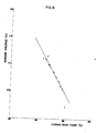
- FIG. 8 shows relation between load signal which is taken out as voltage changes at the point "b” or point "c" in the circuit of FIG. 5 and human thermal sensation.
- the judgement means 28 comprises one-chip microprocessor.
- a ROM preliminarily stores a correction table for correcting non-linearity of the thermistor as the transducer 24 to linear relation and relation of FIG. 8 of human temperature sensation Vs, load signal to be obtained by the control part 26.
- Such storing in the ROM is in the shape of numerical table or numerical equation. Accordingly, the judgement means can issue the output which is substantially equivalent to human thermal sensation to be made by air temperature, air flow and radiation heat in that ambient condition, basing on electric signal from the transducer 24. Therefore, by controlling the air conditioner so as to produce an equilibriumed, by utilizing the output of the judgement part 28 most comfortable environment which takes account of air temperature, air flow and radiant heat is obtainable.
- FIG. 9 shows comparison of outputs of the thermal sensing system 19 under various conditions of air temperature, air flow and number of garments put on with human skin temperature at the same condition.
- This experimental plotting shows that correlation of sensitivity between sensitivities for air temperature and air flow of the thermal sensing system of FIG. 19 with the human body exists.
- FIG. 10 shows characteristic of the radiation of the thermal sensing system 19.
- FIG. 10 shows measured curves of outputs of the thermal sensing system 19 for the cases, where wall temperatures are higher than (right hand curves) and lower than (left hand curves) a fixed temperature of air and feelings stated by test people in the room.
- the graph of FIG. 10 proves that, even under a constant air temperature, the human sensation of temperature varies depending on difference of wall temperatures, namely the radiant temperature from the wall, and that the output of the thermal sensing system in accordance with the present invention agrees with human sensation of temperature.
- the transducer 24 is a thermistor
- a transducer consisting of known platinum resistor as temperature measurement element can be used similarly.
- FIG. 11 shows another embodiment of thermal sensing unit.
- the opening 33 is covered by a porous cover 34, surface of which is non-reflective against light and heat.
- a porous cover 34 of about 60 % aperture ratio made of stainless steel net, surfaces whereof is coated by non-reflective or luster-less black surface paint, is fixed to the opening 33 by a fixing ring 35 fitted to the opening 33 of the shell 36.
- the porous cover 34 may be made of any suitable metal or plastic material.
- FIG. 12 shows another embodiment of the thermal sensing unit.
- the inside reflective face 40 of the shell 39 is configurated as paraboloid of revolution and the transducer 41 is positioned substantially at the focal point of the paraboloid of revolution of the inside reflective face 40.
- the thermal sensing unit is given of directivity against radiation, and therefore it is possible to detect influence of radiation of wall to be measured is possible.
- the shape and size of the transducer 41, hence the sensing unit per se can be made smaller, thereby enabling operation by smaller power.
- the shell 39 can be made by plastic mold with aluminum reflective coating of, for instance, vacuum deposited aluminum film.
- the curved surface of the inside face may be, besides the simple paraboloid of revolution, other curved faces such as composite parboloid of revolution.
- FIG. 13 shows still other embodiment wherein heat insulative material 45 is provided on outside face 44 of the shell 42.
- heat insulative material 45 is provided on outside face 44 of the shell 42.
- FIG. 14 shows still other embodiment wherein at the opening 47 of the shell 50, a porous cover 48 having a convex or hemispherical shape and made of stainless steel sheet is provided.
- the porous cover has about 60 % aspect ratio.
- FIG. 15 and FIG. 16 show still other embodiment.
- the thermal sensing unit 52 comprises a cylindrical shell 54 having a hollow space inside and a wide opening 55 on the top part and made of good reflective material, such as aluminum and of a size of about 30 mm diameter x about 15 mm height, and a transducer 56 provided around on the axis of the shell 54 at a height of about 1/3 from the bottom to the opening edge of the shell 54.
- the transducer 56 comprises a thermistor 57 as temperature sensor at the center and a nickel-chrome wire 58 as a heater wound around the temperature sensor 57 in a manner insulated therefrom.
- a control unit 59 comprises a control part 62 and a judging part 63.
- the control part 62 receives change of temperature inside the transducer 56 determined by cooling effect of environmental air temperature, air flow and radiant temperature to the sensing unit 52, through output signal wires 60, and feed electric power through power feed wires 61 to the heater 58 responding to temperature difference from a preset temperature of substantial the human skin temperature.
- the judgement part 63 receives signal from the control part 62 and issues output signal for controlling an air conditioner 11, basing on judgement made therein taking account of feature of human thermal sensation.
- FIG. 16 is a circuit diagram of one embodiment of the control unit 59, wherein the temperature sensor (thermistor) 57 and resistors 64, 65 and 66 together constitute a bridge circuit.
- the heater 58 is fed with the electric power controlled by an operational amplifier 67, in a manner that the bridge is equilibrated. That is, for instance, when any one item of environmental conditions, i.e. air temperature, air flow or radiant temperature changes thereby to lower the temperature of the thermistor 57, the resistance of the thermistor 57 increases. Thereby the potential of the point “e” rises. Therefore, the operational amplifier 67 amplifies temperature difference between the point “d” and the point “e” of FIG. 15, and hence, the potential of the point “f” rises.
- any one item of environmental conditions i.e. air temperature, air flow or radiant temperature changes thereby to lower the temperature of the thermistor 57
- the resistance of the thermistor 57 increases.
- the operational amplifier 67 amplifies temperature difference between
- the temperature of the thermistor 57 reaches the equilibrium temperature determined by the circuit design.
- a thermistor of a large resistance is preferable.
- the characteristics of the thermal sensing system of this embodiment is greatly improved, like the preceding embodiments.
- thermo sensing system can be provided, which can satisfactorily control any air conditioning apparatuses, not limited to air cooler, but including room warmer, furnace, stove, etc., by measuring the whole environmental temperature conditions including air temperature, air flow and radiant heat which are effective to the human body as a whole.
- the system of the present invention is of compact size and small power consumption, the system can be contained in a battery-operated handy remote controller unit which an easily and accurately senses thermal environmental state, and is useful not only in home, but also in office or shops.
Landscapes
- Engineering & Computer Science (AREA)
- Environmental & Geological Engineering (AREA)
- Life Sciences & Earth Sciences (AREA)
- Atmospheric Sciences (AREA)
- Biodiversity & Conservation Biology (AREA)
- Ecology (AREA)
- Environmental Sciences (AREA)
- Physics & Mathematics (AREA)
- General Physics & Mathematics (AREA)
- Automation & Control Theory (AREA)
- Chemical & Material Sciences (AREA)
- Combustion & Propulsion (AREA)
- Mechanical Engineering (AREA)
- General Engineering & Computer Science (AREA)
- Testing Or Calibration Of Command Recording Devices (AREA)
- Air Conditioning Control Device (AREA)
- Geophysics And Detection Of Objects (AREA)
Applications Claiming Priority (4)
| Application Number | Priority Date | Filing Date | Title |
|---|---|---|---|
| JP29692686A JPH0672814B2 (ja) | 1986-12-12 | 1986-12-12 | 温熱検知装置 |
| JP29692486A JPH0672813B2 (ja) | 1986-12-12 | 1986-12-12 | 温熱検知装置 |
| JP296924/86 | 1986-12-12 | ||
| JP296926/86 | 1986-12-12 |
Publications (2)
| Publication Number | Publication Date |
|---|---|
| EP0274077A1 true EP0274077A1 (de) | 1988-07-13 |
| EP0274077B1 EP0274077B1 (de) | 1991-10-30 |
Family
ID=26560910
Family Applications (1)
| Application Number | Title | Priority Date | Filing Date |
|---|---|---|---|
| EP87118312A Expired - Lifetime EP0274077B1 (de) | 1986-12-12 | 1987-12-10 | Thermische Messeinrichtung |
Country Status (6)
| Country | Link |
|---|---|
| EP (1) | EP0274077B1 (de) |
| KR (1) | KR920006072B1 (de) |
| AU (1) | AU592025B2 (de) |
| CA (1) | CA1307944C (de) |
| DE (1) | DE3774258D1 (de) |
| DK (1) | DK170450B1 (de) |
Cited By (7)
| Publication number | Priority date | Publication date | Assignee | Title |
|---|---|---|---|---|
| EP0526426A1 (de) * | 1991-07-31 | 1993-02-03 | FIAT AUTO S.p.A. | Sensoreinheit für Fahrzeugklimatisierungssysteme |
| EP0495117A4 (en) * | 1990-07-30 | 1993-06-09 | Yamatake-Honeywell Co. Ltd. | Method of computing equivalent temperature and instrument for environment measurement |
| US5324112A (en) * | 1991-07-31 | 1994-06-28 | Fiat Auto S.P.A. | Detector device for evaluating the thermal comfort conditions in an environment, for example, in the interior of a motor vehicle |
| US5558436A (en) * | 1994-07-14 | 1996-09-24 | Landis & Gyr, Inc. | Thermally isolated room temperature sensing apparatus |
| EP1376667A4 (de) * | 2001-03-30 | 2005-01-12 | Tokyo Electron Ltd | Wärmebehandlungseinrichtung |
| CN105101554A (zh) * | 2015-08-17 | 2015-11-25 | 惠州莫思特科技有限公司 | 自动温度控制系统 |
| IT201800020629A1 (it) * | 2018-12-21 | 2020-06-21 | Thinxs S R L | Dispositivo per la misura della temperatura percepita |
Families Citing this family (1)
| Publication number | Priority date | Publication date | Assignee | Title |
|---|---|---|---|---|
| US10151607B2 (en) | 2016-02-26 | 2018-12-11 | Alliance For Sustainable Energy, Llc | Shield devices, systems, and methods for improved measurements and detection |
Citations (2)
| Publication number | Priority date | Publication date | Assignee | Title |
|---|---|---|---|---|
| US3062941A (en) * | 1959-12-14 | 1962-11-06 | Purdue Research Foundation | Radiation-sensitive infrared control |
| US3751634A (en) * | 1971-11-15 | 1973-08-07 | T Madsen | Apparatus for measuring the degree of thermal discomfort and a system comprising such an apparatus |
Family Cites Families (1)
| Publication number | Priority date | Publication date | Assignee | Title |
|---|---|---|---|---|
| CH528084A (de) * | 1971-02-17 | 1972-09-15 | Zellweger Uster Ag | Wärmeempfindliches Gerät, sowie Anwendung desselben |
-
1987
- 1987-12-09 DK DK647887A patent/DK170450B1/da not_active IP Right Cessation
- 1987-12-10 DE DE8787118312T patent/DE3774258D1/de not_active Expired - Lifetime
- 1987-12-10 EP EP87118312A patent/EP0274077B1/de not_active Expired - Lifetime
- 1987-12-11 AU AU82445/87A patent/AU592025B2/en not_active Ceased
- 1987-12-11 CA CA000554143A patent/CA1307944C/en not_active Expired - Lifetime
- 1987-12-12 KR KR1019870014219A patent/KR920006072B1/ko not_active Expired
Patent Citations (2)
| Publication number | Priority date | Publication date | Assignee | Title |
|---|---|---|---|---|
| US3062941A (en) * | 1959-12-14 | 1962-11-06 | Purdue Research Foundation | Radiation-sensitive infrared control |
| US3751634A (en) * | 1971-11-15 | 1973-08-07 | T Madsen | Apparatus for measuring the degree of thermal discomfort and a system comprising such an apparatus |
Non-Patent Citations (2)
| Title |
|---|
| PATENT ABSTRACTS OF JAPAN, vol. 10, no. 15 (P-422)[2072], 21st January 1986; & JP-A-60 170 731 (MATSUSHITA DENKI SANGYO K.K.) 04-09-1985 * |
| PATENT ABSTRACTS OF JAPAN, vol. 8, no. 72 (P-265)[1509], 4th April 1984; & JP-A-58 218 624 (MATSUSHITA DENKI SANGYO K.K.) 19-12-1983 * |
Cited By (11)
| Publication number | Priority date | Publication date | Assignee | Title |
|---|---|---|---|---|
| EP0495117A4 (en) * | 1990-07-30 | 1993-06-09 | Yamatake-Honeywell Co. Ltd. | Method of computing equivalent temperature and instrument for environment measurement |
| EP0526426A1 (de) * | 1991-07-31 | 1993-02-03 | FIAT AUTO S.p.A. | Sensoreinheit für Fahrzeugklimatisierungssysteme |
| US5234049A (en) * | 1991-07-31 | 1993-08-10 | Fiat Auto S.P.A. | Sensor unit for vehicle air-conditioning systems |
| US5324112A (en) * | 1991-07-31 | 1994-06-28 | Fiat Auto S.P.A. | Detector device for evaluating the thermal comfort conditions in an environment, for example, in the interior of a motor vehicle |
| US5558436A (en) * | 1994-07-14 | 1996-09-24 | Landis & Gyr, Inc. | Thermally isolated room temperature sensing apparatus |
| EP1376667A4 (de) * | 2001-03-30 | 2005-01-12 | Tokyo Electron Ltd | Wärmebehandlungseinrichtung |
| US7141765B2 (en) | 2001-03-30 | 2006-11-28 | Tokyo Electron Limited | Heat treating device |
| CN105101554A (zh) * | 2015-08-17 | 2015-11-25 | 惠州莫思特科技有限公司 | 自动温度控制系统 |
| CN105101554B (zh) * | 2015-08-17 | 2018-05-11 | 四川雅全科技有限公司 | 自动温度控制系统 |
| IT201800020629A1 (it) * | 2018-12-21 | 2020-06-21 | Thinxs S R L | Dispositivo per la misura della temperatura percepita |
| WO2020128916A1 (en) * | 2018-12-21 | 2020-06-25 | Thinxs Srl | Device for measuring the perceived temperature |
Also Published As
| Publication number | Publication date |
|---|---|
| AU8244587A (en) | 1988-07-07 |
| DK647887D0 (da) | 1987-12-09 |
| KR880007978A (ko) | 1988-08-30 |
| DK170450B1 (da) | 1995-09-04 |
| EP0274077B1 (de) | 1991-10-30 |
| CA1307944C (en) | 1992-09-29 |
| KR920006072B1 (ko) | 1992-07-27 |
| DK647887A (da) | 1988-06-13 |
| DE3774258D1 (de) | 1991-12-05 |
| AU592025B2 (en) | 1989-12-21 |
Similar Documents
| Publication | Publication Date | Title |
|---|---|---|
| US4890932A (en) | Thermal environment sensor with means to simulate emissivity of human body | |
| US5436852A (en) | Method and apparatus for calculating predicted mean thermal sensitivity | |
| GB2051421A (en) | Temperature regulating system for the control of the temperature in a room | |
| US4433923A (en) | Operative temperature sensing system | |
| EP0274077B1 (de) | Thermische Messeinrichtung | |
| US4964115A (en) | Thermal sensing system | |
| US5732879A (en) | Comfont control by combined temperature and humidity | |
| US3246838A (en) | Controls for infrared emitters | |
| US4164869A (en) | Thermostat system for radiant room heating | |
| JP2629841B2 (ja) | 皮膚温模擬センサ | |
| JPS63128228A (ja) | 温熱検知素子 | |
| JPH0672821B2 (ja) | 温熱検知装置 | |
| JPH0584423B2 (de) | ||
| JP2701275B2 (ja) | 車両用空気調和制御装置用環境検知センサ | |
| JPS60170731A (ja) | 温熱検知素子 | |
| JPH0672817B2 (ja) | 温熱検知装置 | |
| JPH0672813B2 (ja) | 温熱検知装置 | |
| JPH0672816B2 (ja) | 温熱検知装置 | |
| JPH0672814B2 (ja) | 温熱検知装置 | |
| JPH0672815B2 (ja) | 温熱検知装置 | |
| JPH0672819B2 (ja) | 温熱検知装置 | |
| JPH0678920B2 (ja) | 温熱検知装置 | |
| JPH0672820B2 (ja) | 温熱検知装置 | |
| JPH0478132B2 (de) | ||
| JPH0678921B2 (ja) | 温熱検知装置 |
Legal Events
| Date | Code | Title | Description |
|---|---|---|---|
| PUAI | Public reference made under article 153(3) epc to a published international application that has entered the european phase |
Free format text: ORIGINAL CODE: 0009012 |
|
| 17P | Request for examination filed |
Effective date: 19871210 |
|
| AK | Designated contracting states |
Kind code of ref document: A1 Designated state(s): DE FR GB |
|
| 17Q | First examination report despatched |
Effective date: 19900309 |
|
| GRAA | (expected) grant |
Free format text: ORIGINAL CODE: 0009210 |
|
| AK | Designated contracting states |
Kind code of ref document: B1 Designated state(s): DE FR GB |
|
| REF | Corresponds to: |
Ref document number: 3774258 Country of ref document: DE Date of ref document: 19911205 |
|
| ET | Fr: translation filed | ||
| PLBE | No opposition filed within time limit |
Free format text: ORIGINAL CODE: 0009261 |
|
| STAA | Information on the status of an ep patent application or granted ep patent |
Free format text: STATUS: NO OPPOSITION FILED WITHIN TIME LIMIT |
|
| 26N | No opposition filed | ||
| REG | Reference to a national code |
Ref country code: GB Ref legal event code: 746 Effective date: 19960820 |
|
| REG | Reference to a national code |
Ref country code: GB Ref legal event code: IF02 |
|
| PGFP | Annual fee paid to national office [announced via postgrant information from national office to epo] |
Ref country code: DE Payment date: 20041202 Year of fee payment: 18 |
|
| PGFP | Annual fee paid to national office [announced via postgrant information from national office to epo] |
Ref country code: GB Payment date: 20041208 Year of fee payment: 18 Ref country code: FR Payment date: 20041208 Year of fee payment: 18 |
|
| PG25 | Lapsed in a contracting state [announced via postgrant information from national office to epo] |
Ref country code: GB Free format text: LAPSE BECAUSE OF NON-PAYMENT OF DUE FEES Effective date: 20051210 |
|
| PG25 | Lapsed in a contracting state [announced via postgrant information from national office to epo] |
Ref country code: DE Free format text: LAPSE BECAUSE OF NON-PAYMENT OF DUE FEES Effective date: 20060701 |
|
| GBPC | Gb: european patent ceased through non-payment of renewal fee |
Effective date: 20051210 |
|
| PG25 | Lapsed in a contracting state [announced via postgrant information from national office to epo] |
Ref country code: FR Free format text: LAPSE BECAUSE OF NON-PAYMENT OF DUE FEES Effective date: 20060831 |
|
| REG | Reference to a national code |
Ref country code: FR Ref legal event code: ST Effective date: 20060831 |