EP0274082A2 - Dispositif de pulvérisation pour installation d'arrosage - Google Patents
Dispositif de pulvérisation pour installation d'arrosage Download PDFInfo
- Publication number
- EP0274082A2 EP0274082A2 EP87118363A EP87118363A EP0274082A2 EP 0274082 A2 EP0274082 A2 EP 0274082A2 EP 87118363 A EP87118363 A EP 87118363A EP 87118363 A EP87118363 A EP 87118363A EP 0274082 A2 EP0274082 A2 EP 0274082A2
- Authority
- EP
- European Patent Office
- Prior art keywords
- spray
- control
- spray nozzle
- sleeve
- spraying
- Prior art date
- Legal status (The legal status is an assumption and is not a legal conclusion. Google has not performed a legal analysis and makes no representation as to the accuracy of the status listed.)
- Withdrawn
Links
Images


Classifications
-
- B—PERFORMING OPERATIONS; TRANSPORTING
- B05—SPRAYING OR ATOMISING IN GENERAL; APPLYING FLUENT MATERIALS TO SURFACES, IN GENERAL
- B05B—SPRAYING APPARATUS; ATOMISING APPARATUS; NOZZLES
- B05B3/00—Spraying or sprinkling apparatus with moving outlet elements or moving deflecting elements
- B05B3/02—Spraying or sprinkling apparatus with moving outlet elements or moving deflecting elements with rotating elements
- B05B3/04—Spraying or sprinkling apparatus with moving outlet elements or moving deflecting elements with rotating elements driven by the liquid or other fluent material discharged, e.g. the liquid actuating a motor before passing to the outlet
- B05B3/0455—Spraying or sprinkling apparatus with moving outlet elements or moving deflecting elements with rotating elements driven by the liquid or other fluent material discharged, e.g. the liquid actuating a motor before passing to the outlet the outlet elements being rotated by a deflecting element being successively moved into the discharged jet by the action of a biasing means and out of the discharged jet by the discharged jet
-
- B—PERFORMING OPERATIONS; TRANSPORTING
- B05—SPRAYING OR ATOMISING IN GENERAL; APPLYING FLUENT MATERIALS TO SURFACES, IN GENERAL
- B05B—SPRAYING APPARATUS; ATOMISING APPARATUS; NOZZLES
- B05B3/00—Spraying or sprinkling apparatus with moving outlet elements or moving deflecting elements
- B05B3/003—Spraying or sprinkling apparatus with moving outlet elements or moving deflecting elements with braking means, e.g. friction rings designed to provide a substantially constant revolution speed
-
- B—PERFORMING OPERATIONS; TRANSPORTING
- B05—SPRAYING OR ATOMISING IN GENERAL; APPLYING FLUENT MATERIALS TO SURFACES, IN GENERAL
- B05B—SPRAYING APPARATUS; ATOMISING APPARATUS; NOZZLES
- B05B3/00—Spraying or sprinkling apparatus with moving outlet elements or moving deflecting elements
- B05B3/02—Spraying or sprinkling apparatus with moving outlet elements or moving deflecting elements with rotating elements
- B05B3/04—Spraying or sprinkling apparatus with moving outlet elements or moving deflecting elements with rotating elements driven by the liquid or other fluent material discharged, e.g. the liquid actuating a motor before passing to the outlet
- B05B3/0417—Spraying or sprinkling apparatus with moving outlet elements or moving deflecting elements with rotating elements driven by the liquid or other fluent material discharged, e.g. the liquid actuating a motor before passing to the outlet comprising a liquid driven rotor, e.g. a turbine
- B05B3/0446—Spraying or sprinkling apparatus with moving outlet elements or moving deflecting elements with rotating elements driven by the liquid or other fluent material discharged, e.g. the liquid actuating a motor before passing to the outlet comprising a liquid driven rotor, e.g. a turbine with automatic means for regulating the discharged jet
- B05B3/0453—Spraying or sprinkling apparatus with moving outlet elements or moving deflecting elements with rotating elements driven by the liquid or other fluent material discharged, e.g. the liquid actuating a motor before passing to the outlet comprising a liquid driven rotor, e.g. a turbine with automatic means for regulating the discharged jet relative to the angular position of the outlet elements or to the direction of rotation for the outlet elements, e.g. when spraying non-circular areas
Definitions
- the invention relates to a spray device for irrigation systems or the like. With a drivable spray nozzle which is rotatably attached to a fixed supply line of the medium to be sprayed.
- Circular sprinklers of this type are known in numerous different configurations and have also proven themselves in practice.
- the spray nozzles are provided with a rocker arm drive, by means of which the liquid is set in rotation by the flowing water jet.
- these spraying devices only a circular or, if the rocker arm drive is additionally provided with a turning device, a semicircular surface can be sprayed.
- the object of the invention is therefore to provide a spray device for irrigation systems of the aforementioned type, by means of which it is easily possible, despite the Rotational movement of the spray nozzle to produce a rectangular spray pattern, so that even rectangular areas are irrigated. Furthermore, the aim is to ensure that the area to be irrigated is sprayed with water everywhere in an extremely uniform manner. The construction effort required for this should be kept low, nevertheless a satisfactory working method should be guaranteed and an easy installation should be given. Furthermore, existing spraying systems should also be easy to equip without difficulty.
- the spray nozzle is preceded by an allocation device by means of which the amount of the spray medium to be supplied in each case can be regulated depending on the position of the spray nozzle.
- the metering device is to be formed from two control disks which can be rotated relative to one another and are arranged in a planar or spherical manner and into which control openings which are assigned to one another are incorporated in order to change the amount of spray medium through which flow can occur.
- control openings in the end or intermediate walls of two sleeves and / or in the walls thereof, one of which is firmly connected to the feed line of the spray medium and the other sleeve to the spray nozzle and the two sleeves or control disks by means of a union nut or the like. Can be rotated relative to one another, which is supported on one of the sleeves or control disks on a stop surface formed, for example, by a shoulder.
- one of the control disks can also be connected in a rotationally fixed manner to the feed line or an intermediate piece connected to it, and the other control disk can be connected in a rotationally fixed manner to the rotatingly driven spray nozzle via intermediate members.
- control disks or the sleeves rest against one another by the force of a spring, so that they are not lifted apart from one another by the medium to be sprayed and the quantity control is not impaired thereby.
- one of the control disks can be provided with a projecting pin and the other control disk with an associated recess or a molded collar, in which the pin is rotatably held.
- control disks with at least one central through opening, through which the amount of the spray medium corresponding to a circular spray pattern can be fed to a channel connected to the spray nozzle.
- the metering device can also be formed from a periodically effective shut-off valve used in the feed line.
- the shut-off valve can consist of a pin or sleeve attached to a disk or sleeve which is axially adjustable by means of control cams by rotating the spray nozzle and which is non-rotatably supported on the supply line Valve body exist, which cooperates with a recess of another adjacent disc. It is expedient here to hold the axially adjustable disk or sleeve by means of a radially directed pin or the like, which can be pushed against the force of a spring in the supply line or a sleeve or the like connected to it, and to provide a control cam on the end face which cooperates with a control curve attached to the other disc.
- a rotatable driven spray nozzle according to the invention is preceded by an allocation device which is expediently formed from two control disks which are rotatable and provided with control openings, then it is possible with very simple means, despite the rotational movement of the spray nozzle, a square field, or, if the spraying device is equipped with a turning device is to also spray a rectangular field. In the corner areas of such a spray pattern, a larger amount of spray medium is supplied to the spray nozzle, so that a protruding liquid jet is generated and the corner is sprayed out.
- the control of the spray medium to be supplied to the spray nozzle can be controlled with the help of the control disks without difficulty in such a way that a straight-line limitation of the sprayed field can be achieved.
- the spraying device is equipped with a device for periodically regulating the speed of rotation of the spray nozzle. This device thus ensures with certainty that the field to be sprayed is applied uniformly everywhere, despite the larger area in the corner regions of a rectangular field, with the medium to be sprayed.
- the speed control device can be designed in the form of a shoe brake, which is formed by an attachment molded onto one of the control disks that can be rotated relative to one another, e.g. can exist in the form of a pin with a polygonal outer surface, which engages in a recess machined into the other control disk or in a sleeve integrally formed thereon and can be periodically braced therein.
- the shoe brake can, however, also be formed by arms molded onto a ring fixedly connected to the spray nozzle and an adjusting ring arranged on the feed line with a polygonal outer surface against which the arms rest, the contact force of the arms being achieved, for example, by means of a union nut screwed onto the ring should be adjustable.
- the speed device can also be formed by raised control cams formed on the face of the stationary supply line or an intermediate member connected to it and a ring which can be displaced and rotatably fixed on the spray nozzle and which can be rotated against one another against the force of a tensionable spring.
- a brake pad in the form of an intermediate ring made of plastic between the control cams, the preload force of the spring e.g. by means of a nut connected in a rotationally fixed manner to the rotatable control disk via an adapter and to connect the ring to the spray nozzle in a rotationally fixed and axially displaceable manner by means of an axially directed projection which is attached to the spray nozzle and which engages in a groove machined into the ring.
- a spray device that can be inserted periodically into the spray jet to limit the range of the spray jet, e.g. in the form of a baffle, and / or for its atomization, e.g. in the form of an adjustable needle or the like.
- a control member attached to the supply line can be provided, which has a control curve on the outer surface or on an end face, by means of which the device can be pivoted or adjusted in height.
- the feed line can be provided with a marking, for example in the form of a square attachment piece for aligning the spray nozzle.
- the spray device is additionally equipped with a device for periodically regulating the speed of rotation of the spray nozzle and / or with a device that can be inserted periodically into its spray jet to limit the range of the spray jet and / or to atomize it, it is ensured that the field to be sprayed is at all Places is supplied evenly with the spray medium. It is therefore almost impossible that too little water is expelled in the corner areas of a field to be irrigated - by reducing the speed of rotation of the spray nozzle by braking it - rather a compensation is created.
- the measures provided according to the invention thus create a spraying device by means of which rectangular fields can be supplied with a spraying medium precisely and uniformly.
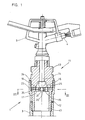
- the spray device shown in FIG. 1 and designated 1 is connected to a fixedly arranged water supply line 3 and serves to supply a square surface 2 with a spray medium, for example water, evenly despite the rotational movement by means of the rotatingly driven spray nozzle 4 according to FIG.
- a drive device 5 is provided for driving the spray nozzle 4. If the drive device 5 is equipped with a turning device, a z. B. with arrangement of the spraying device 1 and the location designated with a of the area to be sprayed 2, a rectangular field 2 ⁇ can be irrigated.
- the spraying device 1 is equipped with an allocation device 11 which is connected upstream of the spray nozzle 4 and by means of which the amount of the sprayed spray medium is controlled depending on the position of the spray nozzle 4 .
- the allocation device 11 consists of two control disks 15 and 16 which are arranged one inside the other and can be rotated relative to one another and which are provided with control openings 18 and 18 and through bores 21 and 22. In the corner areas of the field 2, a larger amount of water can thus be supplied to the spray nozzle 4 via a collecting channel 14 and discharged from it, so that the square field 2 is supplied uniformly with the spraying medium everywhere.
- a union nut 23 is used, which is screwed to the sleeve 13 by means of a thread 24 and on the stop surface 25 formed by a shoulder the control disc 15 rests.
- the control disk 14, on the other hand, is fastened to the sleeve 13 by means of screws 26.
- a pin 20 is integrally formed on the sleeve 13, which is rotatably guided in an associated recess 19 of the control disk 12.
- the cross-sectional areas of the through bores 21 and 22 incorporated into the control disks 15 and 16 are dimensioned such that a circular surface 2 ⁇ could be sprayed by means of the amount of liquid flowing through them.
- the amount of liquid supplied to the collecting duct 14 is increased in a controlled manner in such a way that the spray jet ejected from the spray nozzle 4 increases in its range and after a corner point of the surface 2 ⁇ has been exceeded is again reduced so that a uniform spraying of the entire square field 2 is ensured. Because of the increased liquid supply into the collecting channel 14, the liquid pressure is increased in this, a larger amount of liquid can accordingly be expelled from the spray nozzle 4.
- the total cross-sectional area of the control openings 17 and 18 incorporated in the control disks 15 and 16 and of the through bores 21 and 22, to which the medium to be sprayed flows via a channel 40, is dimensioned larger than the cross-sectional area of the collecting channel 14 leading to the spray nozzle 4 This increases the liquid pressure with increased liquid supply and the range of the liquid jet emerging from the spray nozzle 4 is increased.
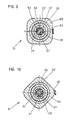
- control openings 17 and 18 incorporated into the control disks 15 and 16 can, as shown in FIG. 3 4, the control openings 17 ⁇ can also be designed in the form of a rhombus or a parallelogram. It is only indicated to increase the through-flowing amount of the liquid to be sprayed to a maximum value with every quarter turn of the spray nozzle 4 and then again to reduce it to the amount required for spraying the circular area 2 ⁇ in order to also hatch the corner area of the field shown in FIG. 2 2 additionally to be supplied with liquid.
- the sleeve 12 ⁇ In the modified configuration of the metering device 11 ist according to FIG. 5, the sleeve 12 ⁇ , the end face of which is designed as a control disk 15 ⁇ provided with control openings 17 ⁇ , is connected in a rotationally fixed manner to the latter by means of a pin 34 which engages in a longitudinal groove 33 machined into the union nut 23 ⁇ .
- an extension in the form of a pin 27 is integrally formed on the sleeve 12 ', which engages in an axially projecting collar 28' which is arranged in the control disk 16 'which is also equipped with control openings 18'.
- control disk 16 ⁇ is held in a rotationally fixed manner by means of a wedge 31 on a sleeve 30 which is connected to the spray nozzle in a driving manner and is rotatably mounted in a nut 13 ⁇ .
- the two control discs 15 ⁇ and 16 ⁇ which are pressed together by the force of a compression spring 32, are thus rotated against each other when the spray nozzle rotates, so that in the corner regions of a field to be sprayed apart from the amount of water which flows through a through hole 21 ⁇ of the control disc 15 ⁇ into one Collection channel 14 ⁇ arrives, a larger amount of water is available via the overlapping control openings 17 ⁇ and 18 ⁇ and recesses 29 incorporated into the collar 28.
- a valve 41 is provided as the allocation device, by means of which the amount of water to be supplied to the collecting duct 14 ⁇ is periodically regulated.
- the valve 41 here consists of a peg-shaped valve body 42 which is formed on a disk 15 ⁇ which has through openings 17 ⁇ and is formed as an intermediate wall of an axially displaceable sleeve 12 ⁇ and which can be inserted into a bore 44 in a further sleeve-like disk 16 ⁇ .
- the disc 16 ' is held in the sleeve 30 by means of an extension 43 and in turn connected to it in a rotationally fixed manner by means of a wedge 31.
- control cams 45 and 46 are worked on the mutually facing end faces of the sleeve 12 ⁇ and the disk 16 ⁇ .
- the sleeve 12 ⁇ which is held in a rotationally fixed manner by means of a pin 34 engaging in a groove 33 of the union nut 23 ⁇ , is displaced axially downward against the force of the spring 32.
- the valve body 42 is thereby guided out of the bore 44, so that in addition to the amount of water flowing through the through hole 21 'into the collecting duct 14', water enters the collecting duct 14 'via the annular gap which is formed.
- a larger one can thus be obtained from the water supply line 3 ⁇ Amount of water get into the collecting channel 14 ⁇ , so that there is also a higher spray pressure.
- the through hole 21 ⁇ can be dispensed with, since the amount of water can be regulated by means of the valve 41 via an adjustable annular gap between the valve body 42 and the disk 16 ⁇ .
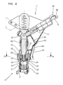
- the spraying device 1 ⁇ shown in FIG. 8 is not only equipped with the metering device 11 ⁇ , but also with a device 51 for periodically regulating the speed of rotation of the spray nozzle 4 ⁇ and with a device 61 for limiting the range of the spray jet, which can also be inserted periodically into it.
- the speed control device 51 is designed in the form of a shoe brake.
- the pin 27 of the control disk 15 ⁇ - the axial section is not placed through the control openings - is designed with a polygonal outer surface in the form of a square 53 which engages in the axially projecting collar 28 attached to the control disk 16 ⁇ .
- the corner dimension of the polygon 53 is larger than the inside diameter of the jaws 52, so that when the control disk 15 ⁇ and 16 ⁇ is rotated relative to one another, as is shown in the sectional drawings in FIGS. 9 and 10, a bracing is effected. In the corner areas of a rectangular to be sprayed Field is automatically reduced in this way the speed of rotation of the spray nozzle 4 ⁇ and thus the amount of water ejected adapted to the enlarged area. This ensures extremely uniform irrigation.
- the device 61 formed by a guide plate 62 is periodically introduced into the spray jet 6.
- a control member 65 which is arranged on the union nut 23 ⁇ and is designed as a square, is used, by means of which the guide plate 62 is controlled via a spring clip 63, which is attached to the spray nozzle 4 ⁇ by a holder 64.
- a rubber band 66 ensures that the spring clip 63 is constantly in contact with the control member 65.
- a control cam 67 is machined on the end face of the control member 65 ⁇ facing the spray nozzle 4 ⁇ , on which the spring clip 63 ⁇ rests.
- the spring clip 63 ⁇ fastened by means of the holder 64 ⁇ and a clamp 68 to the rotatingly driven spray nozzle 4 ⁇ and the guide plate 62 ⁇ formed thereon by a bend are thus also periodically pivoted into the spray jet.
- the spray device 101 shown in FIG. 12 is also equipped with an allocation device 111, a device 121 for limiting or atomizing the spray jet 103 emerging from a spray nozzle 102 and a device 131 for regulating the speed of rotation of the spray nozzle 102.
- the metering device 111 for regulating the amount of water to be supplied to the spray nozzle 102 via a channel 120 again consists of two control disks 112 and 113 which can be rotated relative to one another in an attachment piece 115 and which are pressed against one another by the force of a spring 114 and of which the disk 112 is rotatably fixed in the with the supply line 3 ⁇ connected attachment piece 115 and the disc 113 is operatively connected via a sleeve 118 to the spray nozzle 102.
- the attachment piece 15 is designed as a square, so that it can be used as a marker when aligning the spraying device 101.
- a further nut 117 is held by the sleeve 118, which is screwed into a thread 130 ⁇ of a nut 130 firmly connected to the spray nozzle 102, which nut bears, inter alia, stops 105 for the drive device 104 of the spray nozzle 102 designed as a turning device.
- the device 121 which can be inserted periodically into the spray jet 103, consists of a guide plate 122 which is connected via a linkage 123 to a ring 124 which is arranged to be adjustable in height.
- a longitudinal groove 125 is machined into the ring 124 and a projection 126 is attached to the spray nozzle 102 and engages in the longitudinal groove 125.
- control cams 119 and 128 are incorporated on the nut 117 and on the ring 124 on the mutually facing end faces, so that by twisting the with the Spray nozzle 102 connected ring 124 relative to the nut 117 connected to the water supply line, the ring 124 and thus the baffle 122 are adjusted in height.
- a spring 127 the pretensioning force of which can be adjusted with the aid of the nut 130, ensures that the control cams 119 and 128 are constantly in contact with one another. Furthermore, an adjustable needle 140 is attached to the linkage 123, by means of which the spray jet 103 can also be influenced.
- clamping jaws 132 are provided on the ring 124 and interact with an adjusting ring 133, which has a polygonal outer surface 134.
- a union nut 135 screwed onto the ring 124 the contact force of the clamping jaws 132 on the outer circumferential surface 134 of the non-rotatable adjusting ring 133 can be adjusted.
- the speed of rotation of the spray nozzle 102 is accordingly reduced, so that uniform irrigation of a rectangular field is ensured even in the corner areas despite the enlarged area.
Landscapes
- Nozzles (AREA)
- Catching Or Destruction (AREA)
Applications Claiming Priority (4)
| Application Number | Priority Date | Filing Date | Title |
|---|---|---|---|
| DE3700463 | 1987-01-09 | ||
| DE3700463 | 1987-01-09 | ||
| DE19873730192 DE3730192A1 (de) | 1987-01-09 | 1987-09-09 | Spritzvorrichtung fuer beregnungsanlagen |
| DE3730192 | 1987-09-09 |
Publications (2)
| Publication Number | Publication Date |
|---|---|
| EP0274082A2 true EP0274082A2 (fr) | 1988-07-13 |
| EP0274082A3 EP0274082A3 (fr) | 1989-05-24 |
Family
ID=25851447
Family Applications (1)
| Application Number | Title | Priority Date | Filing Date |
|---|---|---|---|
| EP87118363A Withdrawn EP0274082A3 (fr) | 1987-01-09 | 1987-12-11 | Dispositif de pulvérisation pour installation d'arrosage |
Country Status (2)
| Country | Link |
|---|---|
| EP (1) | EP0274082A3 (fr) |
| DE (1) | DE3730192A1 (fr) |
Cited By (4)
| Publication number | Priority date | Publication date | Assignee | Title |
|---|---|---|---|---|
| EP0822864A4 (fr) * | 1995-04-28 | 1999-05-19 | Michael C Nelson | Dispositif de regulation du debit d'eau destine a un arroseur rotatif |
| CN107051762A (zh) * | 2017-06-07 | 2017-08-18 | 中国地质大学(武汉) | 一种方形喷洒域变量喷洒喷头 |
| EP3332874A3 (fr) * | 2016-11-22 | 2018-08-29 | Rain Bird Corporation | Buse rotative |
| US11406999B2 (en) | 2019-05-10 | 2022-08-09 | Rain Bird Corporation | Irrigation nozzle with one or more grit vents |
Families Citing this family (1)
| Publication number | Priority date | Publication date | Assignee | Title |
|---|---|---|---|---|
| DE4329616A1 (de) * | 1993-09-02 | 1995-03-09 | Gardena Kress & Kastner Gmbh | Regner, insbesondere zur Vegetations-Bewässerung |
Family Cites Families (6)
| Publication number | Priority date | Publication date | Assignee | Title |
|---|---|---|---|---|
| US3884416A (en) * | 1974-08-29 | 1975-05-20 | Norton Paul D | Device for distributing irrigation water |
| US3952954A (en) * | 1975-02-28 | 1976-04-27 | Taylor Robert E | Automatic water sprinkler for irregular areas |
| US4281793A (en) * | 1979-06-25 | 1981-08-04 | Dewitt Robert E | Water sprinkler with flat plate pattern control |
| US4277029A (en) * | 1979-12-03 | 1981-07-07 | Rabitsch Benjamin F | Irrigation sprinkler |
| US4462545A (en) * | 1982-08-10 | 1984-07-31 | Antonio Lourenco | Sprinkler device |
| US4534510A (en) * | 1983-10-21 | 1985-08-13 | Isaac Rinkewich | Area pattern controlled sprinkler |
-
1987
- 1987-09-09 DE DE19873730192 patent/DE3730192A1/de not_active Withdrawn
- 1987-12-11 EP EP87118363A patent/EP0274082A3/fr not_active Withdrawn
Cited By (7)
| Publication number | Priority date | Publication date | Assignee | Title |
|---|---|---|---|---|
| EP0822864A4 (fr) * | 1995-04-28 | 1999-05-19 | Michael C Nelson | Dispositif de regulation du debit d'eau destine a un arroseur rotatif |
| EP3332874A3 (fr) * | 2016-11-22 | 2018-08-29 | Rain Bird Corporation | Buse rotative |
| US10322423B2 (en) | 2016-11-22 | 2019-06-18 | Rain Bird Corporation | Rotary nozzle |
| US11154881B2 (en) | 2016-11-22 | 2021-10-26 | Rain Bird Corporation | Rotary nozzle |
| CN107051762A (zh) * | 2017-06-07 | 2017-08-18 | 中国地质大学(武汉) | 一种方形喷洒域变量喷洒喷头 |
| US11406999B2 (en) | 2019-05-10 | 2022-08-09 | Rain Bird Corporation | Irrigation nozzle with one or more grit vents |
| US12053791B2 (en) | 2019-05-10 | 2024-08-06 | Rain Bird Corporation | Irrigation nozzle with one or more grit vents |
Also Published As
| Publication number | Publication date |
|---|---|
| EP0274082A3 (fr) | 1989-05-24 |
| DE3730192A1 (de) | 1988-07-21 |
Similar Documents
| Publication | Publication Date | Title |
|---|---|---|
| EP0238913A2 (fr) | Buse de pulvérisation pour installation d'arrosage | |
| EP1358945B1 (fr) | Arrangement de buse pour un dispositif pour appliquer un matériau fluide sur un substrat | |
| DE19807973C1 (de) | Spritzvorrichtung zum Zerstäuben von Flüssigkeiten | |
| DE69200277T2 (de) | Vorrichtung zur Herstellung von Schlingen. | |
| DE2737680C3 (de) | Spritzpistole | |
| WO2002087779A1 (fr) | Dispositif de pulverisation pour pulveriser des liquides, notamment a des fins agricoles | |
| DE102010056263A1 (de) | Vorrichtung und Verfahren zum Beschichten eines Gegenstandes mit einem Medium | |
| DE4125012A1 (de) | Einrichtung zum befeuchten von zylindern bei offsetrotationsdruckmaschinen | |
| EP1371421B1 (fr) | Pistolet de pulvérisation | |
| DE2923571C2 (de) | Selbstreinigendes Ventil | |
| EP0274082A2 (fr) | Dispositif de pulvérisation pour installation d'arrosage | |
| DE1621857A1 (de) | Spritzpistole | |
| EP0347551A2 (fr) | Dispositif de commande de débit d'une buse | |
| DE3632846C2 (fr) | ||
| DE2625496A1 (de) | Beregnungseinrichtung, insbesondere sprenger | |
| DE10023672A1 (de) | Vorrichtung zum Auftragen von fließfähigem Material auf ein Substrat sowie Auftragsventil | |
| DE2157337A1 (de) | Zerstäubungsvorrichtung für eine Berieselungseinrichtung | |
| DE10023673A1 (de) | Verteilervorrichtung zum Verteilen von Fluiden sowie Vorrichtung zum Abgeben und Auftragen von Fluid, insbesondere Klebstoff | |
| DE202007007036U1 (de) | Mikrobreitenverstellbare Schlitzdüse | |
| DE19807974C1 (de) | Spritzvorrichtung zum Zerstäuben von Flüssigkeiten | |
| EP4596802A1 (fr) | Inverseur sanitair de fluide et douche sanitaire | |
| DE3404565C2 (de) | Verteilsystem zur tropfenförmigen Verteilung flüssiger Medien | |
| DE19757903A1 (de) | Vorrichtung zum Zerstäuben von Flüssigkeiten | |
| EP1340549A2 (fr) | Pistolet de pulvérisation | |
| DE8700396U1 (de) | Spritzvorrichtung für Beregnungsanlagen |
Legal Events
| Date | Code | Title | Description |
|---|---|---|---|
| PUAI | Public reference made under article 153(3) epc to a published international application that has entered the european phase |
Free format text: ORIGINAL CODE: 0009012 |
|
| AK | Designated contracting states |
Kind code of ref document: A2 Designated state(s): AT CH DE ES FR GB GR IT LI NL |
|
| PUAL | Search report despatched |
Free format text: ORIGINAL CODE: 0009013 |
|
| AK | Designated contracting states |
Kind code of ref document: A3 Designated state(s): AT CH DE ES FR GB GR IT LI NL |
|
| 17P | Request for examination filed |
Effective date: 19891118 |
|
| 17Q | First examination report despatched |
Effective date: 19900924 |
|
| STAA | Information on the status of an ep patent application or granted ep patent |
Free format text: STATUS: THE APPLICATION IS DEEMED TO BE WITHDRAWN |
|
| 18D | Application deemed to be withdrawn |
Effective date: 19911022 |