EP0274150A2 - Moteur synchrone monophasé avec un rotor bipolaire à aimant permanent et avec un rotor intermédiaire à courants de Foucault - Google Patents
Moteur synchrone monophasé avec un rotor bipolaire à aimant permanent et avec un rotor intermédiaire à courants de Foucault Download PDFInfo
- Publication number
- EP0274150A2 EP0274150A2 EP87202376A EP87202376A EP0274150A2 EP 0274150 A2 EP0274150 A2 EP 0274150A2 EP 87202376 A EP87202376 A EP 87202376A EP 87202376 A EP87202376 A EP 87202376A EP 0274150 A2 EP0274150 A2 EP 0274150A2
- Authority
- EP
- European Patent Office
- Prior art keywords
- rotor
- phase synchronous
- synchronous motor
- eddy current
- disc
- Prior art date
- Legal status (The legal status is an assumption and is not a legal conclusion. Google has not performed a legal analysis and makes no representation as to the accuracy of the status listed.)
- Granted
Links
Images
Classifications
-
- H—ELECTRICITY
- H02—GENERATION; CONVERSION OR DISTRIBUTION OF ELECTRIC POWER
- H02K—DYNAMO-ELECTRIC MACHINES
- H02K7/00—Arrangements for handling mechanical energy structurally associated with dynamo-electric machines, e.g. structural association with mechanical driving motors or auxiliary dynamo-electric machines
- H02K7/10—Structural association with clutches, brakes, gears, pulleys or mechanical starters
- H02K7/108—Structural association with clutches, brakes, gears, pulleys or mechanical starters with friction clutches
-
- H—ELECTRICITY
- H02—GENERATION; CONVERSION OR DISTRIBUTION OF ELECTRIC POWER
- H02K—DYNAMO-ELECTRIC MACHINES
- H02K21/00—Synchronous motors having permanent magnets; Synchronous generators having permanent magnets
- H02K21/46—Motors having additional short-circuited winding for starting as an asynchronous motor
Definitions
- the invention relates to a single-phase synchronous motor with a two-pole, permanent-magnet rotor and with an eddy current intermediate rotor, which is non-rotatably connected to the motor shaft and which is rotatable between the stator iron poles and the permanent-magnet rotor, which is freely rotatable on the motor shaft.
- Such a single-phase synchronous motor is known from DE-GmS 84 00 013.
- the motor has a cylindrical, laminated stator with two stator poles that reach into the inside of the cylinder and can be flooded by means of excitation coils.
- a permanent magnetic, cylindrical rotor and a cup-shaped eddy current intermediate rotor made of copper are mounted within the stator poles on the motor axis. While the eddy current intermediate rotor is non-rotatably connected to the motor shaft, the permanent magnet rotor can be freely rotated around the motor shaft.
- This single-phase synchronous motor thus acts simultaneously as a single-phase induction or asynchronous motor; he is preferably intended for a pump drive.
- the permanent-magnet rotor first starts up in synchronism when it starts up, and the eddy currents which form in the eddy-current intermediate rotor cause the intermediate rotor to run up asynchronously, but much more slowly than the permanent-magnetic rotor.
- the advantage of this construction is, among other things, that the tightening torque is significantly greater than that of the pure single-phase synchronous motor.
- the rotor and the eddy current intermediate rotor are disc-shaped and both disks can be axially flooded as a disk arrangement by the stator field via stator iron poles which are located axially on both sides of the disk arrangement.
- stator coils are arranged on iron yokes which connect the stator iron poles outside the disk arrangement, the stator iron poles supporting the bearings of the motor shaft.
- the entire motor thus has the shape of a disk and is nevertheless extremely sturdy because there are no one-sided loads.
- a loaded eddy current intermediate rotor is not able to run up to the full synchronous speed of the permanent magnet rotor.
- the intermediate rotor is provided with a centrifugal clutch which acts on the rotor, which couples it to the intermediate rotor.
- the permanent magnet rotor and the eddy current intermediate rotor are increasingly coupled with one another as the speed increases, so that when the permanent magnetic rotor is finally fully coupled, the eddy current intermediate rotor is completely entrained and dragged up to the synchronous speed.
- the advantageous properties of an eddy current intermediate rotor are coupled with the advantageous properties of a single-phase synchronous motor.
- the centrifugal clutch consists of spring-loaded centrifugal weights which are arranged displaceably in radial guide cages and spring-loaded in the direction of a coupling surface of the rotor.
- the flyweights and guide cages can be provided in molded parts which are molded onto the permanent magnet rotor and onto the eddy current intermediate rotor.
- a non-metallic outer collar is provided on the rotor, which forms an annular groove around the rotor lateral surface, in which engages a non-metallic inner collar of the intermediate disc, which has the guide cages for the outwardly spring-loaded centrifugal weights .
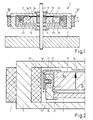
- Fig. 1 shows a single-phase synchronous motor 1, which is designed as an intermediate rotor motor.
- the single-phase synchronous motor 1 has two strip-shaped soft iron poles 3a, 3b which are arranged at a distance from one another and have asymmetrical projections 3c which are connected on opposite sides via iron yokes 5.
- the asymmetrical projections 3c serve to turn the permanent-magnet rotor into a rest position in which the moment exerted on the rotor by the excitation coils is not zero.
- Another possibility of achieving this twist is to provide the iron legs 3a with asymmetrical cutouts.
- Excitation coils 7 are wound over these iron yokes 5.
- the single-phase synchronous motor has a motor shaft 9 which is rotatably supported in the iron poles 3 by means of bearings 11.
- a copper disc 13, which serves as an eddy current intermediate rotor, is arranged in a rotationally fixed manner on the motor shaft 9.
- Axially parallel to the copper disc 13 is a permanent magnetic rotor disc 15 which is magnetized in the axial direction (indicated by arrows 17) and which a bearing 19 is freely rotatable about the motor shaft 9.
- a load 21 is indicated on the motor shaft 9.
- the copper disc 13 used as an eddy current rotor is arranged directly next to the two-pole, permanently magnetic rotor disc 15 and both together form a rotatable disc arrangement 23 which serves to drive the load 21.
- the intermediate rotor disk 13 and the rotor disk 15 are flooded in the axial direction, the flooding of the two motor halves running in opposite directions, as can be seen from the arrows 17 and 17a.
- the rotor 15 runs up to its synchronous speed. Eddy currents form in the intermediate rotor disk 13.
- the intermediate rotor disk 13 loaded with the load 21 thus rotates slowly and, depending on the load, reaches a speed which is below the synchronous speed.
- stator poles are, as is known, asymmetrical.
- centrifugal clutch which is only indicated in FIG. 1, is shown enlarged in FIG. 2 for one engine half.
- the outer surface 25 of the rotor disk 15 is provided with a molded collar 27 which has an outer cylinder 29, a groove 31 forms between and the lateral surface 25.
- the molded collar 27 is preferably made of a non-metallic material, such as plastic.
- a collar 35 for example made of plastic, is also molded onto the outer edge 33 of the intermediate rotor disk 13 and engages freely in the groove 31.
- This collar 35 is provided with guide cages 37 which run in the radial direction. In the guide cages, flyweights 39 are guided in a radially displaceable manner. Springs 41 endeavor to press the flyweights 39 out of the guide cages 37 against the outer cylinders 29.
- the springs 41 constantly press the flyweights 39 against the outer cylinder 29 of the rotor disk 15. The pressure is so minimal, however, that a noticeable braking effect on the rotor disk 15 cannot be determined. If the intermediate disc 13 runs up, the force of the centrifugal weights 36 on the outer cylinder 29 of the rotor disc 15 increases. The friction effect between the rotor disc 15 and the intermediate disc 13 thus increases. Therefore, in addition to the eddy current effect, the intermediate rotor disk 13 is gradually carried along by the permanent magnet rotor 15.
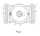
- FIG. 3 are those in FIG. 1 removed iron leg 3c above to be able to look into the engine.
- the permanent magnet rotor 15 and the intermediate rotor disk 13 covered by the rotor 15 are located one above the other between the iron yokes 5 with the excitation coils 7 pushed on. Via the bearing 19, the permanent magnetic rotor is freely rotatably mounted on the shaft 9.
Landscapes
- Engineering & Computer Science (AREA)
- Power Engineering (AREA)
- Permanent Magnet Type Synchronous Machine (AREA)
- Connection Of Motors, Electrical Generators, Mechanical Devices, And The Like (AREA)
- Permanent Field Magnets Of Synchronous Machinery (AREA)
- Dynamo-Electric Clutches, Dynamo-Electric Brakes (AREA)
Priority Applications (1)
| Application Number | Priority Date | Filing Date | Title |
|---|---|---|---|
| AT87202376T ATE77014T1 (de) | 1986-12-06 | 1987-12-01 | Einphasensynchronmotor mit einem zweipoligen, dauermagnetischen rotor und mit einem wirbelstrom-zwischenlaeufer. |
Applications Claiming Priority (2)
| Application Number | Priority Date | Filing Date | Title |
|---|---|---|---|
| DE3641744A DE3641744C1 (de) | 1986-12-06 | 1986-12-06 | Einphasensynchronmotor mit einem Wirbelstrom-Zwischenlaeufer |
| DE3641744 | 1986-12-06 |
Publications (3)
| Publication Number | Publication Date |
|---|---|
| EP0274150A2 true EP0274150A2 (fr) | 1988-07-13 |
| EP0274150A3 EP0274150A3 (en) | 1988-07-27 |
| EP0274150B1 EP0274150B1 (fr) | 1992-06-03 |
Family
ID=6315622
Family Applications (1)
| Application Number | Title | Priority Date | Filing Date |
|---|---|---|---|
| EP87202376A Expired - Lifetime EP0274150B1 (fr) | 1986-12-06 | 1987-12-01 | Moteur synchrone monophasé avec un rotor bipolaire à aimant permanent et avec un rotor intermédiaire à courants de Foucault |
Country Status (5)
| Country | Link |
|---|---|
| US (1) | US4827171A (fr) |
| EP (1) | EP0274150B1 (fr) |
| JP (1) | JPS63144752A (fr) |
| AT (1) | ATE77014T1 (fr) |
| DE (2) | DE3641744C1 (fr) |
Families Citing this family (9)
| Publication number | Priority date | Publication date | Assignee | Title |
|---|---|---|---|---|
| DE3904165A1 (de) * | 1989-02-11 | 1990-08-16 | Hanning Elektro Werke | Selbstanlaufender synchronmotor |
| FR2648632B1 (fr) * | 1989-06-16 | 1991-10-04 | Moving Magnet Tech | Actionneur electromagnetique monophase de faible encombrement |
| US5450770A (en) * | 1993-04-09 | 1995-09-19 | Miles Inc. | Integrated rotary drive apparatus |
| US5363912A (en) * | 1993-05-18 | 1994-11-15 | Eaton Corporation | Electromagnetic coupling |
| US7382072B2 (en) * | 2003-05-22 | 2008-06-03 | Erfurt & Company | Generator |
| KR100565220B1 (ko) * | 2003-10-14 | 2006-03-30 | 엘지전자 주식회사 | 자기저항 동기 전동기 |
| US8193748B2 (en) * | 2008-10-10 | 2012-06-05 | Smi Holdings, Inc. | Integrated brushless DC motor and controller |
| US9484794B2 (en) * | 2012-04-20 | 2016-11-01 | Louis J. Finkle | Hybrid induction motor with self aligning permanent magnet inner rotor |
| US11329537B2 (en) | 2019-05-02 | 2022-05-10 | X Development Llc | Super-synchronous motor/generator |
Family Cites Families (12)
| Publication number | Priority date | Publication date | Assignee | Title |
|---|---|---|---|---|
| US1497394A (en) * | 1919-08-04 | 1924-06-10 | Warren Clock Co | Alternating-current motor |
| US1982826A (en) * | 1929-02-12 | 1934-12-04 | William C Nein | Self-starting synchronous motor |
| US2214850A (en) * | 1939-06-03 | 1940-09-17 | Gen Electric | Self-starting synchronous motor |
| US2725494A (en) * | 1954-09-30 | 1955-11-29 | Gen Electric | Oscillation-suppressed tachometer indicator |
| US2810085A (en) * | 1955-01-31 | 1957-10-15 | Gen Electric | Hysteresis motors |
| FR2147783B1 (fr) * | 1971-06-17 | 1974-06-21 | Mecanique Ind Int | |
| US3753017A (en) * | 1972-02-25 | 1973-08-14 | M Alth | Self starting, single-phase, single-coil induction and synchronous motor |
| CA1004275A (en) * | 1974-04-04 | 1977-01-25 | Canadian General Electric Company Limited | Permanent magnet synchronous dynamoelectric machine |
| FR2425751A1 (fr) * | 1978-05-11 | 1979-12-07 | Valbrev Sarl | Groupe moteur a courant continu sans collecteur |
| US4388545A (en) * | 1981-06-10 | 1983-06-14 | General Electric Company | Rotor for a permanent magnet AC motor |
| DE8400013U1 (de) * | 1984-01-02 | 1985-01-17 | Robert Bosch Gmbh, 7000 Stuttgart | Induktionsmotor |
| HU195598B (en) * | 1986-04-22 | 1988-05-30 | Ipari Mueszergyar | Auxiliary rotor of permanent magnet for asynchronous motors |
-
1986
- 1986-12-06 DE DE3641744A patent/DE3641744C1/de not_active Expired
-
1987
- 1987-12-01 AT AT87202376T patent/ATE77014T1/de not_active IP Right Cessation
- 1987-12-01 DE DE8787202376T patent/DE3779596D1/de not_active Expired - Lifetime
- 1987-12-01 EP EP87202376A patent/EP0274150B1/fr not_active Expired - Lifetime
- 1987-12-03 JP JP62304651A patent/JPS63144752A/ja active Pending
- 1987-12-07 US US07/129,512 patent/US4827171A/en not_active Expired - Fee Related
Also Published As
| Publication number | Publication date |
|---|---|
| US4827171A (en) | 1989-05-02 |
| EP0274150A3 (en) | 1988-07-27 |
| ATE77014T1 (de) | 1992-06-15 |
| JPS63144752A (ja) | 1988-06-16 |
| DE3779596D1 (de) | 1992-07-09 |
| DE3641744C1 (de) | 1988-04-07 |
| EP0274150B1 (fr) | 1992-06-03 |
Similar Documents
| Publication | Publication Date | Title |
|---|---|---|
| DE602004012340T2 (de) | Turbolader mit elektrischem Hilfsantrieb | |
| DE69504318T2 (de) | Elektrische maschinen und ihre komponenten die folienwellenlager enthalten | |
| EP0380744A1 (fr) | Machine électrique | |
| DE843719C (de) | Induktionsmotor | |
| DE2600845A1 (de) | Kreiselpumpe mit kugelmotor | |
| DE69203258T2 (de) | Elektrische Pumpe zur Förderung einer Flüssigkeit, z.B. in Brennkraftmaschinen. | |
| EP0993097A2 (fr) | Moteur à manchon d'entrefer | |
| EP0274150B1 (fr) | Moteur synchrone monophasé avec un rotor bipolaire à aimant permanent et avec un rotor intermédiaire à courants de Foucault | |
| DE3641369C2 (fr) | ||
| DE69608606T2 (de) | Einphasen-Reluktanzmotor mit in einer Phasenwicklung eingebetteten Dauermagneten | |
| DE1299760B (de) | Stillstandsbremse fuer asynchrone Elektromotoren | |
| EP1441432B1 (fr) | Moteur à rotor extérieur, notamment un moteur de petite taille ou un moteur miniature | |
| DE3044576A1 (de) | Rotoranordnung, insbesondere fuer schrittschaltmotoren | |
| DE4229038A1 (de) | Zusatzaggregat, insbesondere Kühlvorrichtung mit einem Lüfter, für eine Maschine, insbesondere für einen Elektromotor | |
| WO2006027043A1 (fr) | Dispositif de circulation de fluides | |
| DE69309288T2 (de) | Elektrischer gebläsemotor | |
| DE3332659C2 (fr) | ||
| DE3400065C2 (fr) | ||
| DE2055516A1 (de) | Kreiselpumpe mit Magnetkupplung | |
| DE3641743C1 (en) | Single-phase synchronous motor having an eddy-current intermediate rotor | |
| DE202005013923U1 (de) | Anordnung zur Förderung von Fluiden | |
| DE202005017738U1 (de) | Anordnung mit einem Lüfter und einer Pumpe | |
| DE112020002212T5 (de) | Rotor für einen Motor sowie Motor, welcher einen solchen Rotor umfasst | |
| DE1538027A1 (de) | Selbstanlaufender Synchronmotor | |
| DE1922735C3 (de) | Vorrichtung zum Antrieb der Trommel einer Waschmaschine mit zwei verschiedenen Drehzahlen |
Legal Events
| Date | Code | Title | Description |
|---|---|---|---|
| PUAI | Public reference made under article 153(3) epc to a published international application that has entered the european phase |
Free format text: ORIGINAL CODE: 0009012 |
|
| PUAL | Search report despatched |
Free format text: ORIGINAL CODE: 0009013 |
|
| AK | Designated contracting states |
Kind code of ref document: A2 Designated state(s): AT DE ES FR GB IT |
|
| AK | Designated contracting states |
Kind code of ref document: A3 Designated state(s): AT DE ES FR GB IT |
|
| 17P | Request for examination filed |
Effective date: 19890117 |
|
| 17Q | First examination report despatched |
Effective date: 19910304 |
|
| GRAA | (expected) grant |
Free format text: ORIGINAL CODE: 0009210 |
|
| AK | Designated contracting states |
Kind code of ref document: B1 Designated state(s): AT DE ES FR GB IT |
|
| PG25 | Lapsed in a contracting state [announced via postgrant information from national office to epo] |
Ref country code: IT Free format text: LAPSE BECAUSE OF FAILURE TO SUBMIT A TRANSLATION OF THE DESCRIPTION OR TO PAY THE FEE WITHIN THE PRE;WARNING: LAPSES OF ITALIAN PATENTS WITH EFFECTIVE DATE BEFORE 2007 MAY HAVE OCCURRED AT ANY TIME BEFORE 2007. THE CORRECT EFFECTIVE DATE MAY BE DIFFERENT FROM THE ONE RECORDED.SCRIBED TIME-LIMIT Effective date: 19920603 |
|
| REF | Corresponds to: |
Ref document number: 77014 Country of ref document: AT Date of ref document: 19920615 Kind code of ref document: T |
|
| REF | Corresponds to: |
Ref document number: 3779596 Country of ref document: DE Date of ref document: 19920709 |
|
| ET | Fr: translation filed | ||
| GBT | Gb: translation of ep patent filed (gb section 77(6)(a)/1977) | ||
| PG25 | Lapsed in a contracting state [announced via postgrant information from national office to epo] |
Ref country code: ES Free format text: LAPSE BECAUSE OF FAILURE TO SUBMIT A TRANSLATION OF THE DESCRIPTION OR TO PAY THE FEE WITHIN THE PRESCRIBED TIME-LIMIT Effective date: 19920914 |
|
| PG25 | Lapsed in a contracting state [announced via postgrant information from national office to epo] |
Ref country code: AT Effective date: 19921201 |
|
| PGFP | Annual fee paid to national office [announced via postgrant information from national office to epo] |
Ref country code: GB Payment date: 19921201 Year of fee payment: 6 |
|
| PGFP | Annual fee paid to national office [announced via postgrant information from national office to epo] |
Ref country code: FR Payment date: 19921222 Year of fee payment: 6 |
|
| PGFP | Annual fee paid to national office [announced via postgrant information from national office to epo] |
Ref country code: DE Payment date: 19930224 Year of fee payment: 6 |
|
| PLBE | No opposition filed within time limit |
Free format text: ORIGINAL CODE: 0009261 |
|
| STAA | Information on the status of an ep patent application or granted ep patent |
Free format text: STATUS: NO OPPOSITION FILED WITHIN TIME LIMIT |
|
| 26N | No opposition filed | ||
| PG25 | Lapsed in a contracting state [announced via postgrant information from national office to epo] |
Ref country code: GB Effective date: 19931201 |
|
| GBPC | Gb: european patent ceased through non-payment of renewal fee |
Effective date: 19931201 |
|
| PG25 | Lapsed in a contracting state [announced via postgrant information from national office to epo] |
Ref country code: FR Effective date: 19940831 |
|
| PG25 | Lapsed in a contracting state [announced via postgrant information from national office to epo] |
Ref country code: DE Effective date: 19940901 |
|
| REG | Reference to a national code |
Ref country code: FR Ref legal event code: ST |