EP0274162A2 - Einstellbare Rohrverzweigung für Zementierkopf - Google Patents
Einstellbare Rohrverzweigung für Zementierkopf Download PDFInfo
- Publication number
- EP0274162A2 EP0274162A2 EP87202628A EP87202628A EP0274162A2 EP 0274162 A2 EP0274162 A2 EP 0274162A2 EP 87202628 A EP87202628 A EP 87202628A EP 87202628 A EP87202628 A EP 87202628A EP 0274162 A2 EP0274162 A2 EP 0274162A2
- Authority
- EP
- European Patent Office
- Prior art keywords
- union
- flange
- mandrel
- cement head
- fluidtight
- Prior art date
- Legal status (The legal status is an assumption and is not a legal conclusion. Google has not performed a legal analysis and makes no representation as to the accuracy of the status listed.)
- Withdrawn
Links
Images


Classifications
-
- F—MECHANICAL ENGINEERING; LIGHTING; HEATING; WEAPONS; BLASTING
- F16—ENGINEERING ELEMENTS AND UNITS; GENERAL MEASURES FOR PRODUCING AND MAINTAINING EFFECTIVE FUNCTIONING OF MACHINES OR INSTALLATIONS; THERMAL INSULATION IN GENERAL
- F16L—PIPES; JOINTS OR FITTINGS FOR PIPES; SUPPORTS FOR PIPES, CABLES OR PROTECTIVE TUBING; MEANS FOR THERMAL INSULATION IN GENERAL
- F16L19/00—Joints in which sealing surfaces are pressed together by means of a member, e.g. a swivel nut, screwed on, or into, one of the joint parts
- F16L19/02—Pipe ends provided with collars or flanges, integral with the pipe or not, pressed together by a screwed member
- F16L19/0231—Pipe ends provided with collars or flanges, integral with the pipe or not, pressed together by a screwed member with specially adapted means for positioning the threaded member behind the collar
-
- E—FIXED CONSTRUCTIONS
- E21—EARTH OR ROCK DRILLING; MINING
- E21B—EARTH OR ROCK DRILLING; OBTAINING OIL, GAS, WATER, SOLUBLE OR MELTABLE MATERIALS OR A SLURRY OF MINERALS FROM WELLS
- E21B33/00—Sealing or packing boreholes or wells
- E21B33/02—Surface sealing or packing
- E21B33/03—Well heads; Setting-up thereof
- E21B33/04—Casing heads; Suspending casings or tubings in well heads
- E21B33/05—Cementing-heads, e.g. having provision for introducing cementing plugs
Definitions
- This invention relates to an adjustable cement head manifold connector and subcombinations thereof. It is particularly useful in the environment in placing a cement casing in a drilled oil well.
- the general technique of placing a casing in a well is set forth in a brochure of the Dowell Division of Dow Chemical Company entitled "Cementing Fundamentals,” the contents of which are incorporated herein by reference.
- the cement head which is connected to a large pump, has a manifold leading to it.
- the manifold connects to at least two openings, and sometimes more, in the cement head.
- the cement head has the purpose of holding a wiper plug which is designed to be run inside the casing ahead of or behind the cement slurry.
- the cement head provides a connection between a cement pump and the well.
- the cement pump pumps cement through the manifold into the head.
- the cementing head has a cap that can be removed for inserting the cement plugs.
- a bottom wiper plug is placed in the cementing head and held in place by a wiper plug retainer. Drilling fluid is pumped through the bottom valve until the fluid has been circulated from the surface down the casing and up the annulus back to the surface. The wiper plug retainer valve is then opened and the cement slurry is pumped through the top valve. The cement slurry pushes the bottom wiper plug down inside the casing.
- the pumping is stopped and a top wiper plug is placed in the cementing head. Then drilling fluid or water is pumped through the top valve, which forces the top wiper plug down inside the casing. Pumping is continued until the top wiper plug seats on the top of the float collar. The well is then shut in until the cement has had time to set.
- the manifold Because of the harsh environment encountered during the cementing of an oil well, the manifold must be very sturdy, have a well-engineered design, and be leak-proof. Moreover, because the inlet and outlets of cement heads vary somewhat in their spacings, many different manifolds have to be utilized. Because of the many different spacings of inlets, sometimes the wrong manifold is forced into place. Accordingly, leaks occur which could cause damaging results to people and equipment.
- One of the results of this invention has been to design a connecting means which has considerably foreshortened the horizontal distance from the cement head to the inlet line, and thus reduce the torque arm which causes damage to the manifold valve or cement head.
- the result of this invention is to provide an adjustable manifold which is safer to use because of its shorter connection to the cement head and which is easily tightened in place in a fluidtight manner for many different spacings of connectors on the cement heads.
- this invention relates to an adjustable cement head manifold connected to the cement head. Because of the similarity of many of the parts, primes and double primes will be utilized where the parts are similar.
- the cement head 10, 10 ⁇ , and 10 ⁇ includes a cylindrical body 12, 12 ⁇ , and 12 ⁇ having a removable top 14, 14 ⁇ , and 14 ⁇ having a holding device 16, 16 ⁇ , and 16 ⁇ .
- the cement head has at least two inlets 18 and 20 which connect to the manifold and valves.
- the outlet 22, 22 ⁇ , and 22 ⁇ engages the well head.
- a plug 23, 23 ⁇ , and 23 ⁇ provides access to the head if necessary.
- Valves 24, 24 ⁇ , 24 ⁇ and 26, 26 ⁇ , 26 ⁇ with wrench pads 25, 25 ⁇ , 25 ⁇ and 27, 27 ⁇ , 27 ⁇ , respectively, to open and close the valves, are provided either after the manifold or as part of it.
- the valves are standard types presently commercially available.
- the first union 28 has a first end 30 and a second end 32.
- a passageway 34 allows fluid to pass through the first union.
- the first end 30 of the first union 28 has an annular flange 36, as particularly noted in FIG. 4.
- An interruption 38 provides an opening through which segments 40 of a retainer ring 42 may pass.
- the interruption 38 must be wide enough for the segments 40 to pass therethrough.
- An annular groove 44 provides a holding means for a snap ring 46. Because the interruption 38 allows the segments 40 to pass therethrough, it is possible to make the end 30 much shorter than the prior art.
- the number of segments 40 may vary from three upwardly, but three rings of 120 degrees and six rings of 60 degrees each have been used successfully.
- the distance from the first end 48 to the center of the passageway 50 is about 8-1/4 inches. Previously, the same dimension was 17-1/2 inches. Accordingly, there has been more than a fifty percent reduction in the length of the first end. As basic physics establishes, the force on the fitting times the lever arm is the torque that has to be sustained by the fittings. This reduction in arm length is a major improvement, resulting in increased life and reduction in problems with cement head manifolds.
- a nut 54 has a radially inwardly projecting flange 56 which acts to engage the flange 36, thus driving the end 48 of the fitting against the inlet of the valve 24.
- a similar second union 51 has a first end 52.
- An inlet connector 53 provides access to the passageway in the second union 51.
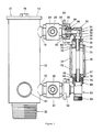
- FIG. 1 illustrates an embodiment of this invention which is used for the highest pressures usually encountered in well casing placements. It has been tested in excess of 15,000 psi. Added strength has been provided by a turnbuckle sleeve 58, with right and left-hand threads, which interacts with complementary threads on nuts 60 and 62.
- the nuts 60 and 62 have internal threads 64 and 68, respectively, and external threads 70 and 72, which act in a manner to separate or bring together the first and second unions.
- a mandrel 74 has one end 76 slidably attached to the second union 51.
- Appropriate O-rings 78 and snap rings 80 are utilized to seal it and hold it in place.
- a piston 82 surrounds the mandrel 74 and has a flange 84 which engages the nut 62.
- the other end 86 of the mandrel has an O-ring 88 in a groove 89 to hold it in fluidtight communication with the second end 32 of the fitting of the first union 28.
- An O-ring 75 is used to seal the nut 60 with the mandrel 74. Holes 90 in the turnbuckle sleeve allow a tool to be used to rotate the sleeve 58.
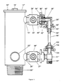
- FIG. 2 is similar in nature to FIG. 1, but is used at slightly lower pressures. Accordingly, it does not need the additional turnbuckle sleeve. It does utilize, however, a mandrel 74 ⁇ having one end 86 ⁇ slidably engaged with a piston or sleeve 76 ⁇ which is held in fluidtight engagement with the second end of the second union 77 ⁇ . The other end of the mandrel similarly has a sleeve or piston 79 ⁇ which is forced against the seat 81 ⁇ of a second end of the first union. An O-ring is provided at 83 in the sleeve to provide a fluidtight connection.
- a nut 85 ⁇ has a flange 87 ⁇ which abuts against the flange on the sleeve and holds the piston 79 in engagement with the union.
- the valves 24 ⁇ and 20 ⁇ are included as part of the first union 28 ⁇ and 51 ⁇ .
- a male threaded extension 89 is available on this embodiment, and may be placed on the others, of course, to act as a support connector for holding the manifold in position.
- FIG. 3 illustrates a third embodiment of this invention, and again similar parts have been similarly numbered using double primes.
- the difference in this embodiment is in the design of the mandrel.
- the slidable engagement of the mandrel 58 ⁇ is with the piston 62 ⁇ .
- the piston 62 ⁇ is held in place by the nut 85 ⁇ by use of its complementary flanges.
- An O'ring 89 ⁇ is utilized to keep a fluidtight connection.
- the end of the mandrel has a male thread 100 which connects with a female thread 102 on a nut 104 to hold the end fixedly engaged with the second union 51 ⁇ .
- FIG. 6 Another alternate embodiment of the invention is illustrated in FIG. 6.
- This embodiment has similar numbers to the other embodiments for similar parts, but utilizes triple primes to indicate the corresponding parts.
- the basic difference in FIG. 6 from the other embodiments is the use of a three-way solenoid valve 26′′′.
- a threaded male member 27′′′ connects to the solenoid valve. Since three-way solenoid valves are well known in the art, specifics of this particular one are not shown. In particular, however, the influx of cement can go either into the upper passage only, the lower passage only, or both simultaneously.
- the top connection 28 may be a "T" instead of the "L" connection in order to provide a means to connect thereto.
- a cement pump may be connected to a great variety of cement heads with the use of this invention instead of the use of different manifolds. More strictlyover, by utilizing different sizes of sleeves, etc., cement heads from 3 inches to 18-1/4 inches can be connected with a manifold of this type. Each of the illustrated devices has a wide range of uses.
- this invention has solved the traditional problem of having many different manifolds that have to be utilized for different cement head dimensional inlets. Moreover, this solution has provided a manifold which is easy to use, safe, and functionally designed for its intended purpose.
Landscapes
- Engineering & Computer Science (AREA)
- General Engineering & Computer Science (AREA)
- Mining & Mineral Resources (AREA)
- Geology (AREA)
- Life Sciences & Earth Sciences (AREA)
- Fluid Mechanics (AREA)
- Environmental & Geological Engineering (AREA)
- Physics & Mathematics (AREA)
- Mechanical Engineering (AREA)
- General Life Sciences & Earth Sciences (AREA)
- Geochemistry & Mineralogy (AREA)
- Reciprocating Pumps (AREA)
- Quick-Acting Or Multi-Walled Pipe Joints (AREA)
Applications Claiming Priority (2)
| Application Number | Priority Date | Filing Date | Title |
|---|---|---|---|
| US48787A | 1987-01-05 | 1987-01-05 | |
| US487 | 1987-01-05 |
Publications (2)
| Publication Number | Publication Date |
|---|---|
| EP0274162A2 true EP0274162A2 (de) | 1988-07-13 |
| EP0274162A3 EP0274162A3 (de) | 1989-12-27 |
Family
ID=21691725
Family Applications (1)
| Application Number | Title | Priority Date | Filing Date |
|---|---|---|---|
| EP87202628A Withdrawn EP0274162A3 (de) | 1987-01-05 | 1987-12-28 | Einstellbare Rohrverzweigung für Zementierkopf |
Country Status (2)
| Country | Link |
|---|---|
| EP (1) | EP0274162A3 (de) |
| CA (3) | CA1280361C (de) |
Family Cites Families (8)
| Publication number | Priority date | Publication date | Assignee | Title |
|---|---|---|---|---|
| DE629111C (de) * | 1936-04-23 | Wolfgang Knochenhauer Dipl Ing | Rohranschluss fuer Rohre mit Dichtkegel mittels UEberwurfmutter und ein- oder mehrteiliger Buechse | |
| US1675808A (en) * | 1927-02-05 | 1928-07-03 | Charles J Kliss | Pipe joint |
| US2438107A (en) * | 1946-06-06 | 1948-03-23 | Electric Steel Foundry | Pipe coupling |
| US2615519A (en) * | 1947-06-30 | 1952-10-28 | Charles J Carr | Plug handling head for well casings |
| US3076509A (en) * | 1958-05-26 | 1963-02-05 | Burns Erwin | Cementing head |
| US3113792A (en) * | 1960-02-16 | 1963-12-10 | Fmc Corp | Pipe union with separable flange for nut |
| DE2204015A1 (de) * | 1972-01-28 | 1973-08-09 | Ermeto Gmbh | Mit kugelgelenken versehene hochdruck-rohrverbindung |
| US4246967A (en) * | 1979-07-26 | 1981-01-27 | The Dow Chemical Company | Cementing head apparatus and method of operation |
-
1987
- 1987-05-25 CA CA000537900A patent/CA1280361C/en not_active Expired - Fee Related
- 1987-12-28 EP EP87202628A patent/EP0274162A3/de not_active Withdrawn
-
1990
- 1990-08-17 CA CA000615835A patent/CA1294539C/en not_active Expired - Fee Related
- 1990-08-17 CA CA000615836A patent/CA1294540C/en not_active Expired - Fee Related
Also Published As
| Publication number | Publication date |
|---|---|
| CA1294540C (en) | 1992-01-21 |
| EP0274162A3 (de) | 1989-12-27 |
| CA1280361C (en) | 1991-02-19 |
| CA1294539C (en) | 1992-01-21 |
Similar Documents
| Publication | Publication Date | Title |
|---|---|---|
| AU645496B2 (en) | Casing head connector | |
| US3860270A (en) | Apparatus for effecting a connection to a tubular member or the like | |
| US4844516A (en) | Connector for coil tubing or the like | |
| AU600214B2 (en) | Drill pipes and casings utilizing multi-conduit tubulars | |
| CA1086223A (en) | Split-ring riser latch | |
| CA1158688A (en) | Remote connector | |
| US3965977A (en) | Control line exiting coupling | |
| US4029118A (en) | Tapping apparatus and method | |
| US4260022A (en) | Through the flow-line selector apparatus and method | |
| US3090437A (en) | Underwater wellhead flow line connector | |
| US4775008A (en) | Adjustable cement head manifold | |
| US4469136A (en) | Subsea flowline connector | |
| US4128127A (en) | Swivel connector | |
| US7163054B2 (en) | Breechblock connectors for use with oil field lines and oil field equipment | |
| US7204304B2 (en) | Removable surface pack-off device for reverse cementing applications | |
| GB2048992A (en) | Method and apparatus for remote installation and servicing of underwater well apparatus | |
| AU675584B2 (en) | Pipe connector | |
| US3957119A (en) | Pump down method | |
| US3534984A (en) | Coupling | |
| US3778089A (en) | Pipe coupling | |
| EP0274162A2 (de) | Einstellbare Rohrverzweigung für Zementierkopf | |
| US4484633A (en) | Safety joint | |
| EP0248893A1 (de) | Hydraulische testeinrichtung für gewinde | |
| US4252187A (en) | Bearing-equipped well tool | |
| GB2048991A (en) | Well tool orientation system with remote indicator |
Legal Events
| Date | Code | Title | Description |
|---|---|---|---|
| PUAI | Public reference made under article 153(3) epc to a published international application that has entered the european phase |
Free format text: ORIGINAL CODE: 0009012 |
|
| AK | Designated contracting states |
Kind code of ref document: A2 Designated state(s): DE FR GB IT NL |
|
| 17P | Request for examination filed |
Effective date: 19881125 |
|
| PUAL | Search report despatched |
Free format text: ORIGINAL CODE: 0009013 |
|
| AK | Designated contracting states |
Kind code of ref document: A3 Designated state(s): DE FR GB IT NL |
|
| STAA | Information on the status of an ep patent application or granted ep patent |
Free format text: STATUS: THE APPLICATION HAS BEEN WITHDRAWN |
|
| 17Q | First examination report despatched |
Effective date: 19910917 |
|
| 18W | Application withdrawn |
Withdrawal date: 19911004 |
|
| R18W | Application withdrawn (corrected) |
Effective date: 19911004 |