EP0274193A2 - Verfahren zum Festlegen der Bedingungen für die Aufstiegszeit bei einem Digital-Oszilloskop - Google Patents
Verfahren zum Festlegen der Bedingungen für die Aufstiegszeit bei einem Digital-Oszilloskop Download PDFInfo
- Publication number
- EP0274193A2 EP0274193A2 EP87309677A EP87309677A EP0274193A2 EP 0274193 A2 EP0274193 A2 EP 0274193A2 EP 87309677 A EP87309677 A EP 87309677A EP 87309677 A EP87309677 A EP 87309677A EP 0274193 A2 EP0274193 A2 EP 0274193A2
- Authority
- EP
- European Patent Office
- Prior art keywords
- time
- risetime
- sweeps
- oscilloscope
- criterion
- Prior art date
- Legal status (The legal status is an assumption and is not a legal conclusion. Google has not performed a legal analysis and makes no representation as to the accuracy of the status listed.)
- Withdrawn
Links
Images


Classifications
-
- G—PHYSICS
- G01—MEASURING; TESTING
- G01R—MEASURING ELECTRIC VARIABLES; MEASURING MAGNETIC VARIABLES
- G01R13/00—Arrangements for displaying electric variables or waveforms
- G01R13/20—Cathode-ray oscilloscopes
- G01R13/22—Circuits therefor
- G01R13/32—Circuits for displaying non-recurrent functions such as transients; Circuits for triggering; Circuits for synchronisation; Circuits for time-base expansion
-
- G—PHYSICS
- G01—MEASURING; TESTING
- G01R—MEASURING ELECTRIC VARIABLES; MEASURING MAGNETIC VARIABLES
- G01R13/00—Arrangements for displaying electric variables or waveforms
- G01R13/20—Cathode-ray oscilloscopes
- G01R13/22—Circuits therefor
- G01R13/34—Circuits for representing a single waveform by sampling, e.g. for very high frequencies
- G01R13/345—Circuits for representing a single waveform by sampling, e.g. for very high frequencies for displaying sampled signals by using digital processors by intermediate A.D. and D.A. convertors (control circuits for CRT indicators)
Definitions
- An oscilloscope is used to acquire, analyze and display electronic signal waveforms.
- the oscilloscope samples electronic signals and plots their waveforms on a cathode ray tube (CRT) display screen in units of voltage versus time.
- CRT cathode ray tube
- voltage amplitude is plotted along the vertical, that is, the Y-axis
- time is plotted along the horizontal, that is, the X-axis.
- digital oscilloscopes have been developed.
- the basic scheme in digital oscilloscope operation is the sampling of a signal, followed by analog-to-digital conversion of the voltage values of the acquired samples.
- the digitized information is then placed in memory and used to create the display of the signal's waveform.
- two chief concerns are the speed and the precision with which the oscilloscope acquires and ultimately displays a signal waveform. The optimal situation is obtained where maximum precision is achieved in a minimum amount of time.
- risetime .35/bandwidth, where bandwidth is the range of signal frequencies, commonly beginning at dc, which the oscilloscope can acquire.
- Risetime is equivalently defined as the amount of time required for a voltage signal to rise from ten percent to ninety percent of its final voltage amplitude.
- the risetime of an oscilloscope is the risetime of the highest frequency signal that the oscilloscope can acquire. The fastest risetime oscilloscopes are the most precise.
- the overall speed of a digital oscilloscope is a function of the speed of acquisition and display routines which the oscilloscope must execute in order to acquire and display a signal waveform. Faster execution of acquisition and display routines will minimize oscilloscope "deadtime", that is, the time spent waiting for routines to complete. During deadtime, data may be missed. Therefore, minimizing sample acquisition and display times will maximize overall speed.
- a digital oscilloscope acquires a signal by sampling it.
- a signal is sampled in cycles known as acquisition-sweeps.
- a sweep occurs whenever the signal crosses a threshold level, known as a trigger.
- acquisition-sweeps occur as a function of a sample clock, such as a 25 Mhz crystal oscillator.
- Samples of the signal are acquired on the rising edge of the sample clock, that is, every 40 nanoseconds, for a 25 MHz clock.
- the number of samples acquired per acquisition-sweep is the value of the user-selected time-range divided by the period of the sample clock.
- the time-range is the width, measured in units of time, of the display screen window.
- the time width of the display screen may be a factor of nanoseconds(ns), microseconds(us), milliseconds(ms), and so on up to some maximum time-range setting.
- the display screen window can be partitioned into a fixed number of discrete time units called time-buckets.
- the time width of each time-bucket varies directly with time-range.
- the time-buckets are mapped into a waveform buffer in memory. Each time-bucket, whether in memory or on the screen, holds a single sample point.
- single-shot sampling also known as real-time sampling
- the signal waveform is acquired on only one acquisition sweep but many points on the waveform are sampled. Once it is acquired, the waveform is displayed.
- repetitive sampling on the other hand, the signal waveform is acquired on repetitive acquisition sweeps and typically fewer points are sampled per sweep.
- single-shot sampling is that non-periodic, "one-time event" signals can be acquired.
- repetitive sampling is that high frequency periodic signals can be acquired.
- a repetitive sampling technique known as random repetitive sampling allows for the capture of higher frequency periodic signals than the sampling rate would otherwise permit, while providing pre-trigger information.
- random repetitive sampling when the input signal crosses a triggering threshold level, a precise measurement is made of the time between the trigger and the time of the next sample, that is, the beginning of the next period of the sample clock. This measurement is used to assign each sample a time coordinate relative to the trigger.
- This method of sampling is random because there is no correlation between the time of the sample and the time of the trigger signal, that is, the two events are asynchronous. This randomness allows for the capture of a higher frequency signal than the rate of the sample clock would otherwise allow.
- This method of sampling is repetitive because the process is repeated at narrow time-range settings until enough points have been collected to accurately reconstruct the waveform for display. This repetitiveness allows for the capture of very high frequency signals.
- the present invention provides a method for determining and executing the minimum number of sample acquisition-sweeps necessary to meet the risetime specifications of a digital oscilloscope which uses random repetitive sampling. Therefore, unnecessary acquisition sweeps are not executed and time consuming display routines are executed only once, after the minimum number of acquisition-sweeps has occurred. Hence, the risetime specification of the digital oscilloscope is met in the shortest amount of time possible.
- the method of the invention selects from two criteria to determine the required number of acquisition sweeps, one for narrow time-ranges when the risetime specification is the determinative factor, and another for wider time-ranges, when the risetime specification is inapplicable.
- a so-called risetime criterion is employed.
- a so-called percentage-filled criterion is employed.
- the minimum number of acquisition sweeps necessary, using either the risetime or the percentage-filled criterion, is determined using a binomial probability formula applied to the variables and relationships which characterize digital oscilloscope operation.
- the present invention calculates the minimum number of acquisition-sweeps necessary to acquire at least one sample point for each one-half-risetime unit of time. This requirement ensures, with statistical reliability, that whenever possible, the risetime specification is met with a minimum number of acquisition-sweeps. Sample point data is displayed only after this number of acquisition-sweeps has been executed, thus reducing the number of acquisition and display routine cycles to a minimum.
- a percentage-filled criterion is used such that the acquired sample points are not displayed until a certain percentage of the time-buckets have been filled, such as eighty-five percent.
- This percentage-filled criterion is also met with a minimum number of acquisition-sweeps.
- the minimum number of acquisition-sweeps necessary for any given time-range setting of a particular oscilloscope is calculated and stored in a look-up table.
- FIG. 1 is a general overview of a digital oscilloscope 5 such as would incorporate the present invention.
- Oscilloscope 5 is operated and controlled by the user with menu keyboard 15.
- Trigger signals for reference and input signals for display are received at ports 20, 25, and 30.
- Input signal waveforms are viewed on display screen 10.
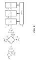
- FIG. 2 is a functional overview of digital oscilloscope 5.
- Sensing circuit 40 detects input signal 35.
- Signal 35 is buffered by pre-amp 45 and applied to sampling bridge 60.
- Clock pulse 50 drives sampling bridge 60 in such a way that a sample of the input signal is passed on to holding cricuit 65 with each period of sampling clock 50.
- Post-amp 70 then delivers the voltage values from holding circuit 65 to analog-to-digital converter 80 (ADC).
- ADC 80 converts the sample voltage values to digital words such that each signal sample is represented by a single digital word.
- the digitized samples produced by ADC 80 are stored in memory structure 90. This digital information is then used to create a display on display screen 10 of the waveform of signal 35.
- Control ciruitry 95 governs the interaction of ADC 80, memory 90 and display screen 10.
- FIG 3 is a schematic depiction of how display screen 10 of Figures 1 and 2 is divided into discrete units of time called time-buckets.
- Display screen 10 may be viewed as a two-dimensional structure having voltage amplitude measured along its vertical axis and time measured along its horizontal axis. Segment 120 of display screen 10 shows that the time axis is resolvable into numerous discrete equal units of time, such as discrete unit 125.
- Each time-bucket is also manifested in memory, as explained below.
- the number of time-buckets, both in memory and on the display screen is fixed.
- the total time-width of display screen 10 may vary.
- the time-width of the display screen 10 is referred to as the time-range.
- the available time-range selections are 10ns, 20ns, 50ns, 100ns, 200ns, 500ns, 1us, 2us, 5us, 10us, 20us, 50us, and so on up to a maximum time-range setting.
- This 1-2-5 sequence of time-range settings follows industry convention.
- the time-width of an individual time-bucket for any given time-range setting will be the time-range setting divided by the number of time-buckets.
- Figure 4 shows the sampling of an input signal 35 and the storage and display in time-buckets of the digitized information.
- Input signal 35 is sampled on the leading edge of each pulse of sample clock 50.
- Typical sample points 130, 132, and 134 are digitized by ADC 80 and stored, at equally spaced intervals, in waveform buffer 121 in time-buckets 130M, 132M and 134M, respectively.
- Time buckets 130M, 132M and 134M are implemented as digital words in waveform buffer 121.
- the sample point data is then mapped from waveform buffer 121 time-buckets 130M, 132M, and 134M to display screen 10 time-buckets 130DS, 132DS and 134DS, respectively.
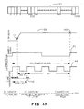
- Figure 4A shows how sample points are assigned addresses and positioned in the time-buckets of waveform buffer 121.
- sample point 140 of input signal 35 can be acquired on the rising edge of sample clock 50.
- a sample of the input signal is acquired once each period of the sample clock.
- sample clock 50 has a 40ns period.
- coarse interpolator (CI) 144 and fine interpolator (FI) 146 are synchronized with sample clock 50 and used to determine the ordinal positioning of acquired sample points in the time-buckets of waveform buffer 121.
- coarse interpolator (CI) 144 has a 10ns period and fine interpolator (FI) 146 has a 50 picosecond(ps) period.
- CI coarse interpolator
- FI fine interpolator
- time-buckets in waveform buffer 121 a single sample point must be assigned to one of 1000 addresses in waveform buffer 121. This assignment of addresses is performed using CI 144 and FI 146.
- Figure 5 shows an expanded view of a typical input signal 35.
- the risetime of signal 35 may be defined as the amount of time required for a signal to rise from ten percent to ninety percent of its final voltage amplitude.
- the risetime specification of an oscilloscope is the risetime t R of the highest frequency signal which the oscilloscope may acquire.
- Figure 5 also illustrates the importance of the time-axis spacing of sample points for accurate reconstruction from samples of input signal 35.
- the risetime of input signal 35 can be determined from sample points 150 and 155.
- line segment 160 connecting sample points 150 and 155 is an accurate reproduction of the actual risetime slope of input signal 35.
- the present invention ensures, with a statistically reliable degree of certainty, that at time-range settings at which the time-width of the time-buckets is less than or equal to one-half of the risetime of the instrument, that there exists at least one sample point for each one-half-risetime unit of time before the contents of the time-buckets in memory are displayed.
- This requirement essentially guarantees that there will be two sample points for each risetime unit of time such that the risetime specification of the instrument is always met at these time-range settings.
- the present invention ensures, with a statistically reliable degree of certainty, that only a minimal number of acquisition-sweeps necessary to meet this risetime criterion is executed, thus reducing acquisition time to a minimum.
- the present invention ensures, with a statistically reliable degree of certainty, that 100 percent of the time-buckets have been filled with sample point data before the display routine is invoked.
- the percentage-filled criterion is met with a minimum number of acquisition-sweeps. This percentage-filled criterion cannot guarantee that the risetime will be met as rigorously as in Figure 5, but it does ensure that enough points will be acquired to produce an accurate display at the wider time-ranges.
- sampling techniques exhibit probabilistic behavior. This behavior can be predicted with well known probability mathematics.
- signals are sampled in acquisition sweeps. Each sweep implies that the signal has crossed a threshold level, known as a trigger.
- the signal's waveform is acquired in one acquisition-sweep, typically with many sample points acquired per sweep.
- repetitive sampling multiple acquisition sweeps are required.
- samples of the waveform are acquired and their relationship to the trigger point is determined.
- the waveform is reconstructed for display by putting all the sample points together while maintaining their timing relationships.
- random repetitive sampling the time between the trigger and the taking of a sample is random, that is, the two events are asynchronous, and this time interval is measured in order to preserve the proper timing relationships between samples when reconstructing the waveform for display.
- the INDEPENDENT case In use of the binomial probability formula, one of two cases, the INDEPENDENT case and the DEPENDENT case, may obtain.
- the trials are independent, that is, the ocuurrence of an event in one trial does not affect the probability of an event in a subsequent trial.
- the DEPENDENT case In the DEPENDENT case, however, the occurrence of an event in one trial does affect the probability of an event in a subsequent trial. This would be the case with repetitive sampling, particularly random repetitive sampling.
- the present invention takes advantage of the foregoing analysis using variables and relationships which characterize digital oscilloscope operation. These are listed in TABLE 1.
- RANGE is the user-selected time-width of display screen 10. RANGE is also the sweep speed of an acquisition-sweep. Narrower RANGE settings have faster sweep speeds.
- the available RANGE selections are 10ns, 20ns, 50ns, 100ns, 200ns, 500ns, 1us, 2us, 5us, 10us, 20us, 50us and so on up to a maximum RANGE setting.
- This 1-2-5 sequence of RANGE settings follows industry convention. For an input signal with a frequency within the bandwidth of the oscilloscope, the RANGE setting will determine how much of the signal's waveform is visible on the display screen. For instance, at the 2us RANGE setting a full period of an input signal may be visible while at the 1us RANGE setting only half of a period of the same signal is visible.
- the POINTS_PER_SWEEP number is the number of sample points that may be collected in one acquisition-sweep when input signal 35 is sampled. At wide RANGE settings, many samples can be collected in a single acquisition-sweep. At the lowest RANGE setting, several acquisition-sweeps may be required to acquire a single sample point.
- the time- width of each time-bucket will be less than or equal to one-half of the RISETIME of the instrument at known RANGE settings. At each of these RANGE settings it is therefore possible to acquire at least two samples points for every RISETIME unit of time, which is all that is necessary to meet the risetime specifications of the instrument. On the other hand, beginning at a certain RANGE setting, it will no longer be possible to guarantee acquisition of two sample points for every RISETIME unit of time because the time-width of each time-bucket will be greater than RISETIME/2.
- the risetime criterion cannot be used at the RANGE of 1us and above because RANGE/NUMBER_OF_TIME BUCKETS > RISETIME/2, that is, 1us/1000 > 0.625ns. At these RANGE settings the percentage filled criterion then applies.
- PROBABILITY is the desired percentage of certainty, expressed as a number between 0 and 1, that a given event will occur.
- MIN_SWEEPS is the minimum number of acquisition sweeps which must be performed to meet either the risetime or the percentage-filled criterion, depending upon the user-selected RANGE setting.
- TABLE 2 shows the values of the variables of TABLE 1 when using the risetime criterion definition of MIN_PTS for the time-ranges at which the risetime criteria is applicable, that is, when RANGE divided by the number of time-buckets is less than or equal to one-half of the risetime of the oscilloscope.
- MIN_PTS equals RANGE divided by one-half-RISETIME.
- TABLE 3 shows the values of the variables of TABLE 1 when using the percentage-filled criterion definition of MIN_SWEEPS, that is, where MIN_SWEEPS equals the number of time-buckets times the percentage-filled criterion desired.
- MIN_SWEEPS equals the number of time-buckets times the percentage-filled criterion desired.
- numerical results for both an 80 percent and a 100 percent percentage-filled criterion are shown.
- numerical results are shown for both the risetime criterion RANGE settings and the percentage-filled criterion RANGE settings.
- MIN_PTS as well as DIV_FACTOR, is a constant number over all but the two most narrow RANGE settings, 10ns and 20ns.
- This anomaly is a function of the resolution of FI 146, the 50ps fine interpolator clock.
- the number of time-buckets in waveform buffer 121 is a constant, 1000, for every RANGE setting.
- the 1000 time-buckets in waveform buffer 121 are addressed at these RANGE settings by multiplying the time-bucket addresses generated at the 10ns RANGE by 5 and those generated at the 20ns RANGE by 2.5.
- the risetime criterion method of calculating MIN_SWEEPS generates a smaller MIN_SWEEPS number for the RANGE settings 10ns through 500ns, the time-ranges for which RANGE/NUMBER_OF_TIME_BUCKETS is less than or equal to RISETIME/2.
- the risetime specification of the instrument can be met more quickly with fewer acquisition sweeps at these RANGE settings using the risetime criterion definition of MIN_SWEEPS.
- FIG. 6 is a macro-level flowchart showing the steps of the present invention.
- the first step 300 is to determine the RANGE value.
- the RANGE value will be set by the oscilloscope user.
- the next step 305 is to determine if the RANGE value divided by the number of time-buckets at that time-range is less than or equal to one-half of the risetime of the oscilloscope. If so then the risetime criterion MIN_SWEEPS number of acquisition sweeps for that RANGE is executed, as listed in TABLE 2. Otherwise, the percentage-filled MIN_SWEEPS number of acquisition-sweeps is executed, as listed in TABLE 3.
- the proper MIN_SWEEPS number is simply accessed from a memory array, indexed by RANGE settings.
- the display routine is invoked and the waveform displayed. The steps are then repeated. Hence, the number of aquisition-sweep and display routine cycles is minimized while at the same time maximum precision is achieved whenever possible.
- FIG. 7 is a micro-level flowchart showing the steps of the present invention.
- the first step 400 is to determine the MIN_SWEEPS number based upon the RANGE setting. MIN_SWEEPS can be automatically found in a memory array having the appropriate MIN_SWEEPS number indexed by RANGE, similar in form to TABLES 2 and 3.
- the next step 405 is the initialization to zero of the counter variable SWEEP_COUNT.
- the next step 410 is the activation of sample acquisition hardware.
- the next step 415 is execution of an aquisition-sweep.
- the next step 425 is storage of the acquired sample points in waveform buffer 121.
- SWEEP_COUNT is incremented after each acquisition-sweep in step 430. Then another check is made in step 435 to determine if SWEEP_COUNT equals MIN_SWEEPS. If so, the waveform buffer is sent to display, otherwise another acquisition-sweep is executed pursuant to step 440.
Landscapes
- Physics & Mathematics (AREA)
- General Physics & Mathematics (AREA)
- Debugging And Monitoring (AREA)
- Complex Calculations (AREA)
- Controls And Circuits For Display Device (AREA)
- Measurement Of Resistance Or Impedance (AREA)
Applications Claiming Priority (2)
| Application Number | Priority Date | Filing Date | Title |
|---|---|---|---|
| US929551 | 1986-11-10 | ||
| US06/929,551 US4719416A (en) | 1986-11-10 | 1986-11-10 | Method for determining the minimum number of acquisition sweeps to meet the risetime specifications of a digital oscilloscope |
Publications (2)
| Publication Number | Publication Date |
|---|---|
| EP0274193A2 true EP0274193A2 (de) | 1988-07-13 |
| EP0274193A3 EP0274193A3 (de) | 1989-12-13 |
Family
ID=25458042
Family Applications (1)
| Application Number | Title | Priority Date | Filing Date |
|---|---|---|---|
| EP87309677A Withdrawn EP0274193A3 (de) | 1986-11-10 | 1987-11-02 | Verfahren zum Festlegen der Bedingungen für die Aufstiegszeit bei einem Digital-Oszilloskop |
Country Status (3)
| Country | Link |
|---|---|
| US (1) | US4719416A (de) |
| EP (1) | EP0274193A3 (de) |
| JP (1) | JP2591965B2 (de) |
Cited By (1)
| Publication number | Priority date | Publication date | Assignee | Title |
|---|---|---|---|---|
| EP0933638A3 (de) * | 1998-01-28 | 2000-12-20 | Tektronix, Inc. | Cursordarstellung der Anstiegs-/Abfallzeit einer Wellenform |
Families Citing this family (19)
| Publication number | Priority date | Publication date | Assignee | Title |
|---|---|---|---|---|
| US4789950A (en) * | 1986-09-11 | 1988-12-06 | Tektronix, Inc. | Pre-interpolation adaptive filter |
| US4809189A (en) * | 1986-10-09 | 1989-02-28 | Tektronix, Inc. | Equivalent time waveform data display |
| US5111191A (en) * | 1988-06-23 | 1992-05-05 | Motorola, Inc. | Method and apparatus for waveform digitization |
| US5214784A (en) * | 1988-11-28 | 1993-05-25 | Tektronix, Inc. | Sequence of events detector for serial digital data which selectively outputs match signal in the series which defines detected sequence |
| US5148230A (en) * | 1990-04-25 | 1992-09-15 | Tektronix, Inc. | Measurement apparatus having improved sample density using nested data acquisitions |
| US5212485A (en) * | 1990-09-27 | 1993-05-18 | Tektronix, Inc. | Analog oscilloscope digitizer |
| US5155431A (en) * | 1991-02-06 | 1992-10-13 | Hewlett-Packard Company | Very fast autoscale topology for digitizing oscilloscopes |
| US5115189A (en) * | 1991-02-06 | 1992-05-19 | Hewlett-Packard Company | Anti-aliasing dithering method and apparatus for low frequency signal sampling |
| US5375067A (en) * | 1992-12-11 | 1994-12-20 | Nicolet Instrument Corporation | Method and apparatus for adjustment of acquisition parameters in a data acquisition system such as a digital oscilloscope |
| US6263290B1 (en) * | 1995-02-22 | 2001-07-17 | Michael K. Williams | Process and machine for signal waveform analysis |
| US5907000A (en) * | 1997-03-07 | 1999-05-25 | The Walman Optical Company | Adjustable refractive index coating composition |
| US6246389B1 (en) * | 1997-06-03 | 2001-06-12 | Agilent Technologies, Inc. | Simulating analog display slew rate intensity variations in a digital graphics display |
| US6195617B1 (en) * | 1998-03-09 | 2001-02-27 | Lecroy, S.A. | Digital storage oscilloscope with simultaneous primary measurement and derived parameter display on common time axis and method therefor |
| US6278268B1 (en) * | 2000-02-11 | 2001-08-21 | Agilent Technologies, Inc. | Method for controlling scale parameters of an instrument in response to input to an event-generating control sensor |
| US6856924B2 (en) * | 2003-02-25 | 2005-02-15 | Agilent Technologies, Inc. | Mixer-based timebase for sampling multiple input signal references asynchronous to each other |
| US6700516B1 (en) | 2003-02-25 | 2004-03-02 | Agilent Technologies, Inc. | Mixer-based timebase for signal sampling |
| DE102005035394A1 (de) * | 2005-07-28 | 2007-02-15 | Rohde & Schwarz Gmbh & Co Kg | Verfahren und System zur digitalen Triggerung von Signalen auf der Basis von zwei zeitlich beabstandeten Triggerereignissen |
| US8024140B2 (en) * | 2007-08-23 | 2011-09-20 | Amherst Systems Associates, Inc. | Waveform anomoly detection and notification systems and methods |
| CN119375527B (zh) * | 2024-10-18 | 2026-01-23 | 电子科技大学 | 智能示波器的自适应高精度采集方法 |
Family Cites Families (6)
| Publication number | Priority date | Publication date | Assignee | Title |
|---|---|---|---|---|
| US4142146A (en) * | 1975-07-07 | 1979-02-27 | Nicolet Instrument Corporation | Digital apparatus for waveform measurement |
| US4104725A (en) * | 1976-03-26 | 1978-08-01 | Norland Corporation | Programmed calculating input signal module for waveform measuring and analyzing instrument |
| US4283713A (en) * | 1979-01-15 | 1981-08-11 | Tektronix, Inc. | Waveform acquisition circuit |
| US4495586A (en) * | 1982-07-29 | 1985-01-22 | Tektronix, Inc. | Waveform acquisition apparatus and method |
| US4578667A (en) * | 1984-03-23 | 1986-03-25 | Tektronix, Inc. | Digital acquisition system including a high-speed sampling gate |
| US4694244A (en) * | 1986-02-21 | 1987-09-15 | Hewlett Packard Company | Apparatus for random repetitive sampling |
-
1986
- 1986-11-10 US US06/929,551 patent/US4719416A/en not_active Expired - Lifetime
-
1987
- 1987-11-02 EP EP87309677A patent/EP0274193A3/de not_active Withdrawn
- 1987-11-09 JP JP62282925A patent/JP2591965B2/ja not_active Expired - Fee Related
Cited By (1)
| Publication number | Priority date | Publication date | Assignee | Title |
|---|---|---|---|---|
| EP0933638A3 (de) * | 1998-01-28 | 2000-12-20 | Tektronix, Inc. | Cursordarstellung der Anstiegs-/Abfallzeit einer Wellenform |
Also Published As
| Publication number | Publication date |
|---|---|
| JP2591965B2 (ja) | 1997-03-19 |
| JPS63132174A (ja) | 1988-06-04 |
| US4719416A (en) | 1988-01-12 |
| EP0274193A3 (de) | 1989-12-13 |
Similar Documents
| Publication | Publication Date | Title |
|---|---|---|
| US4719416A (en) | Method for determining the minimum number of acquisition sweeps to meet the risetime specifications of a digital oscilloscope | |
| US4705345A (en) | Addressing liquid crystal cells using unipolar strobe pulses | |
| US6799144B2 (en) | Method and apparatus for analyzing measurements | |
| US4975636A (en) | Method and apparatus for selecting and displaying a high resolution window from a main display | |
| JP2733746B2 (ja) | ロジック信号表示方法 | |
| EP0234883B1 (de) | Apparatur und Methode für wiederholendes Zufallssampling | |
| CN1230683C (zh) | 初级测量值与导出参数的同时显示 | |
| US6263290B1 (en) | Process and machine for signal waveform analysis | |
| CA1191274A (en) | Waveform acquisition apparatus and method | |
| EP0506223B1 (de) | Sehr schnelle Autoskaliertopologie für Digitaloszilloskope | |
| US6271773B1 (en) | Coherent sampling method and apparatus | |
| US4777616A (en) | Increased resolution logic analyzer using asynchronous sampling | |
| US7653500B2 (en) | Sequential timebase | |
| US5315627A (en) | Pseudo-random repetitive sampling of a signal | |
| KR20010050448A (ko) | 시간 간격 분배 측정에서 디지털화 아티팩트를최소화시키는 파형 시간 스탬핑 방법 | |
| EP0235911B1 (de) | Niveaudetektor für ein Wellenform-Abtastsystem | |
| US7216046B2 (en) | Method of generating a variable persistence waveform database | |
| US6522983B1 (en) | Timebase calibration method for an equivalent time sampling digitizing instrument | |
| US4703448A (en) | Method for measuring skew or phase difference in electronic systems | |
| EP0444875A2 (de) | Verfahren und Anordnung zur Vergrösserung des Durchsatzes in Zufallsfolge zyklischer Digitalisierungssysteme | |
| US4529930A (en) | Programmable delay for digitizer circuits | |
| CN112051425B (zh) | 等效时间采样系统中的模式采集 | |
| EP1783505B1 (de) | Komprimierter logischer Abtastspeicher | |
| US4916677A (en) | Automatic period and frequency measurements | |
| US5268851A (en) | Detection of metastability in triggers |
Legal Events
| Date | Code | Title | Description |
|---|---|---|---|
| PUAI | Public reference made under article 153(3) epc to a published international application that has entered the european phase |
Free format text: ORIGINAL CODE: 0009012 |
|
| AK | Designated contracting states |
Kind code of ref document: A2 Designated state(s): DE FR GB |
|
| PUAL | Search report despatched |
Free format text: ORIGINAL CODE: 0009013 |
|
| AK | Designated contracting states |
Kind code of ref document: A3 Designated state(s): DE FR GB |
|
| 17P | Request for examination filed |
Effective date: 19900420 |
|
| 17Q | First examination report despatched |
Effective date: 19920122 |
|
| STAA | Information on the status of an ep patent application or granted ep patent |
Free format text: STATUS: THE APPLICATION IS DEEMED TO BE WITHDRAWN |
|
| 18D | Application deemed to be withdrawn |
Effective date: 19920804 |
|
| RIN1 | Information on inventor provided before grant (corrected) |
Inventor name: DESAUTELS, PATRICIA A. |