EP0274206A2 - Erwärmen von Gegenständen in einer Erwärmungskammer - Google Patents
Erwärmen von Gegenständen in einer Erwärmungskammer Download PDFInfo
- Publication number
- EP0274206A2 EP0274206A2 EP87310297A EP87310297A EP0274206A2 EP 0274206 A2 EP0274206 A2 EP 0274206A2 EP 87310297 A EP87310297 A EP 87310297A EP 87310297 A EP87310297 A EP 87310297A EP 0274206 A2 EP0274206 A2 EP 0274206A2
- Authority
- EP
- European Patent Office
- Prior art keywords
- heating
- chamber
- heating chamber
- stock
- plenum
- Prior art date
- Legal status (The legal status is an assumption and is not a legal conclusion. Google has not performed a legal analysis and makes no representation as to the accuracy of the status listed.)
- Granted
Links
Images

Classifications
-
- F—MECHANICAL ENGINEERING; LIGHTING; HEATING; WEAPONS; BLASTING
- F27—FURNACES; KILNS; OVENS; RETORTS
- F27B—FURNACES, KILNS, OVENS OR RETORTS IN GENERAL; OPEN SINTERING OR LIKE APPARATUS
- F27B17/00—Furnaces of a kind not covered by any of groups F27B1/00 - F27B15/00
- F27B17/0016—Chamber type furnaces
- F27B17/0083—Chamber type furnaces with means for circulating the atmosphere
-
- C—CHEMISTRY; METALLURGY
- C21—METALLURGY OF IRON
- C21D—MODIFYING THE PHYSICAL STRUCTURE OF FERROUS METALS; GENERAL DEVICES FOR HEAT TREATMENT OF FERROUS OR NON-FERROUS METALS OR ALLOYS; MAKING METAL MALLEABLE, e.g. BY DECARBURISATION OR TEMPERING
- C21D1/00—General methods or devices for heat treatment, e.g. annealing, hardening, quenching or tempering
- C21D1/34—Methods of heating
- C21D1/52—Methods of heating with flames
-
- C—CHEMISTRY; METALLURGY
- C21—METALLURGY OF IRON
- C21D—MODIFYING THE PHYSICAL STRUCTURE OF FERROUS METALS; GENERAL DEVICES FOR HEAT TREATMENT OF FERROUS OR NON-FERROUS METALS OR ALLOYS; MAKING METAL MALLEABLE, e.g. BY DECARBURISATION OR TEMPERING
- C21D1/00—General methods or devices for heat treatment, e.g. annealing, hardening, quenching or tempering
- C21D1/74—Methods of treatment in inert gas, controlled atmosphere, vacuum or pulverulent material
- C21D1/767—Methods of treatment in inert gas, controlled atmosphere, vacuum or pulverulent material with forced gas circulation; Reheating thereof
-
- C—CHEMISTRY; METALLURGY
- C21—METALLURGY OF IRON
- C21D—MODIFYING THE PHYSICAL STRUCTURE OF FERROUS METALS; GENERAL DEVICES FOR HEAT TREATMENT OF FERROUS OR NON-FERROUS METALS OR ALLOYS; MAKING METAL MALLEABLE, e.g. BY DECARBURISATION OR TEMPERING
- C21D9/00—Heat treatment, e.g. annealing, hardening, quenching or tempering, adapted for particular articles; Furnaces therefor
- C21D9/0081—Heat treatment, e.g. annealing, hardening, quenching or tempering, adapted for particular articles; Furnaces therefor for slabs; for billets
Definitions
- the present invention relates to the heating of stock in a heating chamber to which a heating gas is supplied to heat the stock.
- a method for heating stock comprising feeding stock to be heated into a heating chamber, causing heating gas to enter the heating chamber to heat the stock and leave the heating chamber after heating the stock and then removing the stock from the heating chamber on completion of heating, the heating gas being allowed to enter the heating chamber by way of a plenum chamber which communicates with the heating chamber.
- apparatus for heating stock comprising a heating chamber for receiving the stock for heating with a heating gas, a plenum chamber which communicates with the heating chamber, a fuel-fired burner for supplying heating gas to the plenum chamber for distribution to the heating chamber, there being means for exhausting waste gas from the heating chamber.
- apparatus for heating stock comprising a heating chamber for receiving the stock for heating with a heating gas, a first plenum chamber adjoining a first side of the heating chamber and communicating with the chamber through the first side, a second plenum chamber adjoining a second side of the heating chamber and communicating with the chamber through the second side, a first regenerative type burner communicating with the first plenum chamber and a second regenerative type burner communicating with the second plenum chamber, each burner being adapted on its firing cycle to supply heating gas to its plenum chamber for subsequent distribution to the heating chamber for heating the stock and on its flueing cycle to receive from its plenum chamber waste gas discharged from the heating chamber, the arrangement being that, in use, while one burner is firing the other is flueing.
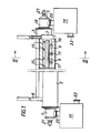
- the apparatus comprises a heating chamber 1, two plenum chambers 2,3 each communicating with the heating chamber 1 and a pair of regenerative type burners 4,5, one burner communicating with a matching plenum chamber.
- the heating chamber 1 comprises an elongate generally rectangular or circular cross section furnace which is designed to reheat metal stock such as large section round or square billets.
- the chamber 1 forms an elongate enclosure 6 to receive the stock to be heated such as a long billet (eg. an aluminium log) or a multiplicity of billets (such as those used in forging or extrusion).
- the enclosure 6 is closed at either end by doors 7 and 8 which are raisable vertically to permit entry and discharge of a billet (such as that shown by reference 9).
- the billet 9 enters via door 7 and leaves via door 8.
- the floor 10 of the enclosure 6 is provided with a means of stock conveying such as driven rolls 11 along which the billet 9 can be moved into and out of the enclosure 6.
- the plenum chamber 2 is displaced slightly vertically below the plenum chamber 3 and the plenum chambers 2,3 and the heating chamber 1 are refractory lined 16 and contained in an outermost casing 17.
- Each plenum chambers 2,3 is either closed at one end (not shown) and is provided at the other end with a regenerative type burner 4,5 each of which is arranged adjacent opposite ends of the heating chamber 1 or provided with regenerative type burners on both ends.
- the regenerative burners 4,5 are of conventional construction and comprise a fuel-fired burner 18 and associated regenerator chamber 19.
- each regenerative burner supplies its plenum chamber with heating gas in the form of fuel combustion products.
- each burner receives waste gas from its plenum chamber for subsequent discharge.
- the regenerator chamber 19 communicates with the burner part 18 by way of a duct 20.
- the regenerator chamber 19 supplies the burner part 18 with preheated air by way of the duct 20 for combustion with fuel, eg. natural gas supplied to the burner part 18 by a fuel pipe 21.
- fuel eg. natural gas supplied to the burner part 18 by a fuel pipe 21.
- the air for preheating in the regenerator 19 is supplied to the regenerator 19 by a pipe 22.
- the stock heating can either be “batch” or “continuous” depending upon the process requirements.
- one burner would fire into its plenum chamber for the complete heating cycle of the one billet within the heating chamber.
- the other plenum chamber would act as a manifold for receiving the waste combustion products from the heating chamber with the other burner operating in a flueing mode.
- the firing burner could be shut down whilst the heated billet was removed from the heating chamber which would be recharged with cold stock.
- the burner which had previously been flueing would now fire while that burner which had previously been firing would now serve as a flue. This cycle would be repeated.
- each burner firing period could be of predetermined duration, possibly to coincide with the discharge interval of the stock, or alternatively, the firing period could be controlled by the temperature of the waste gases leaving the regenerator of the burner which is flueing.
- the provision of the plenum chambers along the sides of the heating chamber enables the heating gas to be distributed to the heating chamber in a far more uniform manner than would be the case if as conventional the burners were to be firing directly into the heating chamber. Furthermore, the provision of plenum chambers enables the number of burners per particular heating chamber to be reduced together with the number and complexity of controls.
Landscapes
- Chemical & Material Sciences (AREA)
- Engineering & Computer Science (AREA)
- Mechanical Engineering (AREA)
- Physics & Mathematics (AREA)
- Thermal Sciences (AREA)
- Crystallography & Structural Chemistry (AREA)
- Materials Engineering (AREA)
- Metallurgy (AREA)
- Organic Chemistry (AREA)
- General Engineering & Computer Science (AREA)
- Tunnel Furnaces (AREA)
- Forging (AREA)
Applications Claiming Priority (2)
| Application Number | Priority Date | Filing Date | Title |
|---|---|---|---|
| GB8700219 | 1987-01-07 | ||
| GB8700219A GB2199643B (en) | 1987-01-07 | 1987-01-07 | Apparatus for heating stock |
Publications (3)
| Publication Number | Publication Date |
|---|---|
| EP0274206A2 true EP0274206A2 (de) | 1988-07-13 |
| EP0274206A3 EP0274206A3 (en) | 1989-08-16 |
| EP0274206B1 EP0274206B1 (de) | 1992-07-29 |
Family
ID=10610332
Family Applications (1)
| Application Number | Title | Priority Date | Filing Date |
|---|---|---|---|
| EP87310297A Expired EP0274206B1 (de) | 1987-01-07 | 1987-11-20 | Erwärmen von Gegenständen in einer Erwärmungskammer |
Country Status (5)
| Country | Link |
|---|---|
| US (1) | US4840560A (de) |
| EP (1) | EP0274206B1 (de) |
| JP (1) | JPS63183122A (de) |
| DE (1) | DE3780792T2 (de) |
| GB (1) | GB2199643B (de) |
Cited By (1)
| Publication number | Priority date | Publication date | Assignee | Title |
|---|---|---|---|---|
| EP0368633A3 (de) * | 1988-11-08 | 1991-01-16 | British Gas plc | Verfahren und Apparat für die Heizung eines Gefässes |
Families Citing this family (4)
| Publication number | Priority date | Publication date | Assignee | Title |
|---|---|---|---|---|
| GB2215031B (en) * | 1988-02-11 | 1992-04-22 | Stordy Combustion Eng | Radiant tube furnace and method of burning a fuel |
| US4944670A (en) * | 1989-12-15 | 1990-07-31 | North American Manufacturing Co. | Self-cleaning burner |
| US5161968A (en) * | 1991-05-21 | 1992-11-10 | Process Combustion Corporation | Regenerative thermal oxidizer |
| USRE43252E1 (en) | 1992-10-27 | 2012-03-20 | Vast Power Portfolio, Llc | High efficiency low pollution hybrid Brayton cycle combustor |
Family Cites Families (20)
| Publication number | Priority date | Publication date | Assignee | Title |
|---|---|---|---|---|
| GB143653A (en) * | 1919-03-06 | 1920-06-03 | George Hillard Benjamin | Improvements in tunnel kilns |
| US1522166A (en) * | 1921-11-28 | 1925-01-06 | American Dressler Tunnel Kilns | Kiln and method of operating same |
| DE568300C (de) * | 1926-08-20 | 1933-01-17 | E H Heinrich Koppers Dr Ing | Tunnelofen |
| GB333192A (en) * | 1929-02-01 | 1930-08-01 | Herbert Schaefer | Improvements in a process for heating in a gaseous atmosphere particularly in a reducing or oxidising atmosphere |
| US1860887A (en) * | 1930-08-19 | 1932-05-31 | Charles E Buysse | Furnace |
| GB1233549A (de) * | 1967-11-09 | 1971-05-26 | ||
| US3712597A (en) * | 1970-11-18 | 1973-01-23 | Air Preheater | Glass manufacturing system |
| BE789508A (fr) * | 1971-10-08 | 1973-01-15 | Werner & Pfleiderer | Four tunnel continu de cuisson ou de sechage |
| LU65915A1 (de) * | 1972-08-17 | 1974-02-21 | ||
| GB1523121A (en) * | 1975-10-24 | 1978-08-31 | Ass Elect Ind | Furnaces |
| DE2712989C2 (de) * | 1977-03-24 | 1985-04-25 | Metallgesellschaft Ag, 6000 Frankfurt | Zündofen zur Zündung von Sintermischungen |
| US4160641A (en) * | 1977-09-15 | 1979-07-10 | Holcroft & Company | Continuous furnace |
| DE2929322C2 (de) * | 1979-07-19 | 1984-05-17 | Friedrich Wilhelm Dipl.-Ing. 5600 Wuppertal Elhaus | Anwärmofen |
| US4358268A (en) * | 1980-12-15 | 1982-11-09 | Neville Warren H | Furnace system with reheated flue gas recirculation |
| JPS5827924A (ja) * | 1981-08-13 | 1983-02-18 | Daido Steel Co Ltd | 被熱物の加熱方法 |
| US4410308A (en) * | 1982-01-04 | 1983-10-18 | Mcelroy James G | Combustion furnace and burner |
| US4529379A (en) * | 1983-09-28 | 1985-07-16 | Dicastri Peter | Cooking apparatus |
| DE3339585C1 (de) * | 1983-11-02 | 1987-11-12 | Didier Engineering Gmbh, 4300 Essen | Wärmofen zum Nachwärmen von Röhren, Sonderprofilen und dergleichen Wärmgut |
| DE3418603C1 (de) * | 1984-05-18 | 1985-03-21 | Schweizerische Aluminium Ag, Chippis | Anwaermofen fuer zylindrische Gueter |
| DE3440048C1 (de) * | 1984-11-02 | 1986-03-27 | Didier Engineering Gmbh, 4300 Essen | Nachwaermofen fuer Brammen oder Bloecke |
-
1987
- 1987-01-07 GB GB8700219A patent/GB2199643B/en not_active Expired - Fee Related
- 1987-11-20 DE DE8787310297T patent/DE3780792T2/de not_active Expired - Fee Related
- 1987-11-20 EP EP87310297A patent/EP0274206B1/de not_active Expired
- 1987-11-25 US US07/125,333 patent/US4840560A/en not_active Expired - Lifetime
-
1988
- 1988-01-06 JP JP63001141A patent/JPS63183122A/ja active Granted
Cited By (1)
| Publication number | Priority date | Publication date | Assignee | Title |
|---|---|---|---|---|
| EP0368633A3 (de) * | 1988-11-08 | 1991-01-16 | British Gas plc | Verfahren und Apparat für die Heizung eines Gefässes |
Also Published As
| Publication number | Publication date |
|---|---|
| DE3780792T2 (de) | 1993-03-04 |
| DE3780792D1 (de) | 1992-09-03 |
| GB2199643B (en) | 1990-06-20 |
| EP0274206A3 (en) | 1989-08-16 |
| GB2199643A (en) | 1988-07-13 |
| GB8700219D0 (en) | 1987-02-11 |
| EP0274206B1 (de) | 1992-07-29 |
| JPH0437143B2 (de) | 1992-06-18 |
| US4840560A (en) | 1989-06-20 |
| JPS63183122A (ja) | 1988-07-28 |
Similar Documents
| Publication | Publication Date | Title |
|---|---|---|
| US4373702A (en) | Jet impingement/radiant heating apparatus | |
| US4790749A (en) | Kiln for firing ceramic materials such as tiles and the like | |
| EP0736732A4 (de) | Strahlbohrbrenner und verfahren zum betrieb | |
| US4225121A (en) | Energy efficient heat-treating furnace system | |
| US4840560A (en) | Heating stock in a heating chamber | |
| US4309171A (en) | Billet heating furnace with pressurized entrance seal | |
| JPH05172465A (ja) | 連続焼成炉の温度制御装置 | |
| RU2045725C1 (ru) | Способ обжига керамических изделий и устройство для его осуществления | |
| US3601375A (en) | Glass annealing lehrs | |
| JPH06228632A (ja) | 加熱設備およびそれを使用した加熱方法 | |
| JP3419917B2 (ja) | 連続加熱装置 | |
| CA1332510C (en) | Gas burner forced convection heating of glass sheets | |
| EP0247007A2 (de) | Rollenherdofen mit einer Bahn zum Trocknen und/oder Wiederbrennen für feuerfeste Produkte | |
| RU2022035C1 (ru) | Способ отопления двухкамерной печи и печь для нагрева заготовок | |
| SU1010143A1 (ru) | Способ термической обработки изделий | |
| GB2045408A (en) | Furnace system | |
| CN2363258Y (zh) | 连续式燃煤热处理炉 | |
| RU2155722C2 (ru) | Нагревательное устройство с принудительной конвекцией и способ нагрева в нем листового стекла | |
| US1809628A (en) | Means for utilizing the waste gases from furnaces | |
| SU679163A3 (ru) | Туннельна печь дл обжига керамических изделий | |
| JPH0236647B2 (ja) | Renzokukanetsuroniokeruhaigasuryohoho | |
| SU1064104A1 (ru) | Нагревательна кузнечна печь | |
| US2961732A (en) | Preheating section for tunnel kiln and method | |
| JP2000273530A (ja) | 鋼材の連続加熱装置 | |
| SU1183803A1 (ru) | Печь дл нагрева изделий |
Legal Events
| Date | Code | Title | Description |
|---|---|---|---|
| PUAI | Public reference made under article 153(3) epc to a published international application that has entered the european phase |
Free format text: ORIGINAL CODE: 0009012 |
|
| AK | Designated contracting states |
Kind code of ref document: A2 Designated state(s): BE DE FR IT NL |
|
| 17P | Request for examination filed |
Effective date: 19880614 |
|
| PUAL | Search report despatched |
Free format text: ORIGINAL CODE: 0009013 |
|
| AK | Designated contracting states |
Kind code of ref document: A3 Designated state(s): BE DE FR IT NL |
|
| RAP1 | Party data changed (applicant data changed or rights of an application transferred) |
Owner name: BRITISH GAS PLC |
|
| 17Q | First examination report despatched |
Effective date: 19910603 |
|
| GRAA | (expected) grant |
Free format text: ORIGINAL CODE: 0009210 |
|
| AK | Designated contracting states |
Kind code of ref document: B1 Designated state(s): BE DE FR IT NL |
|
| ITF | It: translation for a ep patent filed | ||
| REF | Corresponds to: |
Ref document number: 3780792 Country of ref document: DE Date of ref document: 19920903 |
|
| ET | Fr: translation filed | ||
| PLBE | No opposition filed within time limit |
Free format text: ORIGINAL CODE: 0009261 |
|
| STAA | Information on the status of an ep patent application or granted ep patent |
Free format text: STATUS: NO OPPOSITION FILED WITHIN TIME LIMIT |
|
| 26N | No opposition filed | ||
| PGFP | Annual fee paid to national office [announced via postgrant information from national office to epo] |
Ref country code: FR Payment date: 20011012 Year of fee payment: 15 |
|
| PGFP | Annual fee paid to national office [announced via postgrant information from national office to epo] |
Ref country code: NL Payment date: 20011026 Year of fee payment: 15 |
|
| PGFP | Annual fee paid to national office [announced via postgrant information from national office to epo] |
Ref country code: DE Payment date: 20011029 Year of fee payment: 15 |
|
| PGFP | Annual fee paid to national office [announced via postgrant information from national office to epo] |
Ref country code: BE Payment date: 20011115 Year of fee payment: 15 |
|
| PG25 | Lapsed in a contracting state [announced via postgrant information from national office to epo] |
Ref country code: BE Free format text: LAPSE BECAUSE OF NON-PAYMENT OF DUE FEES Effective date: 20021130 |
|
| BERE | Be: lapsed |
Owner name: *BG PUBLIC LIMITED COMPANY Effective date: 20021130 |
|
| PG25 | Lapsed in a contracting state [announced via postgrant information from national office to epo] |
Ref country code: NL Free format text: LAPSE BECAUSE OF NON-PAYMENT OF DUE FEES Effective date: 20030601 |
|
| PG25 | Lapsed in a contracting state [announced via postgrant information from national office to epo] |
Ref country code: DE Free format text: LAPSE BECAUSE OF NON-PAYMENT OF DUE FEES Effective date: 20030603 |
|
| PG25 | Lapsed in a contracting state [announced via postgrant information from national office to epo] |
Ref country code: FR Free format text: LAPSE BECAUSE OF NON-PAYMENT OF DUE FEES Effective date: 20030731 |
|
| NLV4 | Nl: lapsed or anulled due to non-payment of the annual fee |
Effective date: 20030601 |
|
| REG | Reference to a national code |
Ref country code: FR Ref legal event code: ST |
|
| PG25 | Lapsed in a contracting state [announced via postgrant information from national office to epo] |
Ref country code: IT Free format text: LAPSE BECAUSE OF NON-PAYMENT OF DUE FEES Effective date: 20051120 |