EP0274559A2 - Injecteur de lubrifiant et dispositif pour lubrifier des points de graissage mobiles - Google Patents
Injecteur de lubrifiant et dispositif pour lubrifier des points de graissage mobiles Download PDFInfo
- Publication number
- EP0274559A2 EP0274559A2 EP87103888A EP87103888A EP0274559A2 EP 0274559 A2 EP0274559 A2 EP 0274559A2 EP 87103888 A EP87103888 A EP 87103888A EP 87103888 A EP87103888 A EP 87103888A EP 0274559 A2 EP0274559 A2 EP 0274559A2
- Authority
- EP
- European Patent Office
- Prior art keywords
- piston
- lubricant
- injector
- control
- lubrication
- Prior art date
- Legal status (The legal status is an assumption and is not a legal conclusion. Google has not performed a legal analysis and makes no representation as to the accuracy of the status listed.)
- Granted
Links
- 238000005461 lubrication Methods 0.000 title claims abstract description 44
- 230000001050 lubricating effect Effects 0.000 title claims abstract description 22
- 239000000314 lubricant Substances 0.000 claims abstract description 83
- 210000002445 nipple Anatomy 0.000 claims abstract description 33
- 238000000034 method Methods 0.000 claims abstract description 13
- 230000008569 process Effects 0.000 claims abstract description 13
- 230000009471 action Effects 0.000 claims description 9
- 238000006073 displacement reaction Methods 0.000 claims description 8
- 239000004519 grease Substances 0.000 claims description 8
- 230000004888 barrier function Effects 0.000 claims description 4
- 230000001960 triggered effect Effects 0.000 claims description 3
- 230000008878 coupling Effects 0.000 claims description 2
- 238000010168 coupling process Methods 0.000 claims description 2
- 238000005859 coupling reaction Methods 0.000 claims description 2
- 230000001419 dependent effect Effects 0.000 claims description 2
- 238000003825 pressing Methods 0.000 claims description 2
- 230000001360 synchronised effect Effects 0.000 claims description 2
- 239000006096 absorbing agent Substances 0.000 description 3
- 230000006835 compression Effects 0.000 description 2
- 238000007906 compression Methods 0.000 description 2
- 238000010586 diagram Methods 0.000 description 2
- 239000003973 paint Substances 0.000 description 2
- 238000007789 sealing Methods 0.000 description 2
- 230000035939 shock Effects 0.000 description 2
- 230000008859 change Effects 0.000 description 1
- 238000000576 coating method Methods 0.000 description 1
- 238000010276 construction Methods 0.000 description 1
- 230000008020 evaporation Effects 0.000 description 1
- 238000001704 evaporation Methods 0.000 description 1
- 239000012530 fluid Substances 0.000 description 1
- 230000003993 interaction Effects 0.000 description 1
- 238000004519 manufacturing process Methods 0.000 description 1
- 239000000463 material Substances 0.000 description 1
- 238000010422 painting Methods 0.000 description 1
- 239000002245 particle Substances 0.000 description 1
- 230000009467 reduction Effects 0.000 description 1
- 230000000284 resting effect Effects 0.000 description 1
- 230000002123 temporal effect Effects 0.000 description 1
Images



Classifications
-
- F—MECHANICAL ENGINEERING; LIGHTING; HEATING; WEAPONS; BLASTING
- F16—ENGINEERING ELEMENTS AND UNITS; GENERAL MEASURES FOR PRODUCING AND MAINTAINING EFFECTIVE FUNCTIONING OF MACHINES OR INSTALLATIONS; THERMAL INSULATION IN GENERAL
- F16N—LUBRICATING
- F16N13/00—Lubricating-pumps
- F16N13/02—Lubricating-pumps with reciprocating piston
- F16N13/06—Actuation of lubricating-pumps
- F16N13/16—Actuation of lubricating-pumps with fluid drive
-
- B—PERFORMING OPERATIONS; TRANSPORTING
- B65—CONVEYING; PACKING; STORING; HANDLING THIN OR FILAMENTARY MATERIAL
- B65G—TRANSPORT OR STORAGE DEVICES, e.g. CONVEYORS FOR LOADING OR TIPPING, SHOP CONVEYOR SYSTEMS OR PNEUMATIC TUBE CONVEYORS
- B65G45/00—Lubricating, cleaning, or clearing devices
- B65G45/02—Lubricating devices
- B65G45/08—Lubricating devices for chains
Definitions
- the invention relates to a lubricant injector for a device for lubricating traveling lubrication points, in particular for rollers of a chain conveyor, the bearings of which can be refilled with lubricant via a lubrication nipple, onto which the injector can be pressed during the lubrication process, with a spring-loaded delivery piston arranged in a housing for the lubricant obtained via an inlet and an injector tip designed to be placed on the lubricating nipple.
- the invention further relates to a device for lubricating migrating lubrication points, in particular a central lubrication system for rollers of a chain conveyor.
- Such a central lubrication system is known for lubricating the idler rollers of a chain conveyor, with which body parts are moved from a paint shop into an oven for burning the paint. Due to the temperature stress and the associated evaporation of a permanent filling of the roller bearings with lubricant, it is necessary to supply the bearings of the supporting rollers with a metered amount of lubricant according to the need for a circulation of the chain.
- a central nipple is provided in the roller holder or on the roller bolt, which supplies the interior of the associated roller with lubricant for the bearing via a transverse bore, when lubricant is supplied under pressure through an injector placed on the nipple.
- the known injector of this central lubrication system has a compressed air-actuated delivery piston in a housing, with which a predetermined volume of lubricant can be expelled through the injector tip to the lubrication nipple.
- a check valve is located in the injector tip. In the discharge cycle, the piston is moved back into its rest position by a compression spring, whereby lubricant gets under the delivery piston again.
- the invention has for its object to avoid a lubricant injector and a lubricating device while avoiding the specified disadvantages, with which an accurate dosage of the amount of lubricant dispensed without residual dripping is made possible for both oil and fluid grease and the lubrication process especially with regard to the synchronization of parts to be moved with one another and the positioning with respect to one another is significantly improved in terms of accuracy.
- a lubricant injector in that an actuated by compressed air in the housing rer spring-loaded displacement piston is arranged, which is connected to the injector tip, that an annular space is left between the displacement piston and the housing, which connects the lubricant inlet via a bore with a cylinder space formed coaxially in the displacement piston, that a cylinder body for a spring-loaded spring in the cylinder space Control piston and the delivery piston with play to form an overflow channel leading from one side of the delivery piston to the other side, and that the cylinder body leaves a pre-control space in the cylinder space and channels controlled by the control piston to one side of the delivery piston and can be connected to the overflow channel Has control channels.
- a cuff is arranged in the injector tip in the dispensing channel, which forms an additional guarantee against dripping.
- control pistons and delivery pistons can be loaded by the same springs in order to reduce the manufacturing effort and costs.
- the control piston has between its two ends an annular space formed by reducing the cross section, which in the working position establishes the connection from the pilot space to the control channel, which is directly connected to one side of the delivery piston, the one to which Control channel leading overflow channel is closed by the control piston.
- a star disk can be provided, which is arranged between the cylinder body and the injector tip and leaves open openings for shifting the lubricant.
- the device for lubricating migrating lubrication points in particular central lubrication system for rollers of a chain conveyor, the bearings of which can be refilled with lubricant via a lubrication nipple, has a feed line, a compressed air-actuated lubricant injector with the above-mentioned features, which can be moved onto the lubrication nipple, and a path-dependent control of the lubrication process , wherein the device according to the invention is characterized in that the injector is arranged on a slide which is movable with the lubricating nipple and can be coupled to its movement, that the coupling between the slide injector and the lubricating nipple can be triggered by a control element which is switched by the part to be lubricated and which actuates a compressed air cylinder , whose piston rod has a lever is connected to a driver of the slide for synchronous movement slide injector / grease nipple
- two injectors are arranged opposite one another, which carry out the lubrication process either simultaneously or individually activated, two levers and drivers arranged opposite one another being connected to the piston rod of the compressed air cylinder.
- An impact damper is expediently provided to limit the return path of the slide.
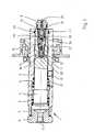
- the lubricant injector 1 consists essentially of a hollow cylindrical housing 2, in which one by means of compressed air Actuatable, by a spring 3 loaded piston 4 is arranged.
- a step 5 is formed in the housing 2 for mounting the spring 3.
- a corresponding step on the left side of the traversing piston 4 in the drawing serves as abutment for the return spring 3, the back stop of which is formed in the travel path by a stopper 6 screwed into the housing at the end with a central air supply 7.
- the travel piston 4 is connected to an injector tip 8.
- an annular space 9 is left in the central region, which connects a lubricant inlet 10 formed in the housing 2 via a transverse bore 11 of the traversing piston to a cylinder space 12 which is coaxial in the traversing piston (on the right in the drawing).
- the cylinder chamber 12 is stepped several times, so that a cylinder body 13 can be inserted into it from the front side, which is held on the back with a shoulder on a step and on the delivery side by the screwed-in injector tip 8, a star disk 14 being inserted between the injector tip 8 and the cylinder body 13 which leaves openings for the shifting of lubricant.
- the cylinder body 13 receives a control piston 16 loaded by a spring 15 and a delivery piston 18 loaded by an equally large spring 17 in the same effective direction, the position of which can be adjusted to change the delivery rates.
- a control piston 16 loaded by a spring 15
- a delivery piston 18 loaded by an equally large spring 17 in the same effective direction, the position of which can be adjusted to change the delivery rates.
- the cylinder body 13 is inserted with play to the cylinder chamber 12 of the travel piston 4, so that there there is an annulus. Furthermore, the cylinder body 13 leaves a pilot space 20 on the left in the cylinder space and is controlled by the control piston 16 channels 21 (FIG. 2 of the drawing) to one side of the Delivery piston (left side in the drawing) and further control channels 22 and 66, which can be connected to the overflow channel 19, are formed in the cylinder body 13.
- a hole is provided centrally in the injector tip 8 as a lubricant discharge channel 23, which connects the right-hand side of the delivery piston 18 to a removal opening 24 of the injector tip 8 which is designed to be suitable for a conical nipple or funnel nipple.
- a sleeve 25 is inserted, the frustoconical shape of which only releases the flow in the direction of removal under the lubricant pressure, but closes tightly in the opposite direction.
- the cylinder bore for the control piston 16 is closed with respect to the cylinder bore for the delivery piston 18 by an inserted separator 26.
- the control piston 16 has a cross-sectional reduction approximately in the middle, which creates an annular space 28 to the cylinder body 13, which represents an overflow space for lubricant.
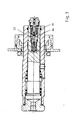
- Fig. 2 of the drawing shows the pressure stroke, in the sub pressurizing the lubricant inlet 10, the pressurization via the annular space 9, the transverse bores 11 in the traversing piston are transmitted to the pilot chamber 20.
- the control piston 16 Upon the action of the spring 15, the control piston 16 is shifted into its right-hand position shown in FIG. 2 of the drawing, so that lubricant from the pilot chamber 20 via the control channels 21, the annular space 28 in the control piston and the control channels 22 below the delivery piston 18 (left side).
- the control channel 66 is closed in this position.
- the delivery piston 18 moves to the right against the action of its spring 17 and displaces the chimeric material stored in front of it (right side) through the discharge channel 23 and the removal opening 24 into the lubricating nipple fitted in this position as a consumer point.
- the supply pressure is currently greater than the spring forces.
- the picture results in the relaxation cycle according to FIG. 3 of the drawing.
- the spring 15 brings the control piston 16 into its left position in the drawing. It is sealed against the pilot chamber, so that when the delivery piston 18 is also initiated due to the action of its spring 17 to the left in the drawing, lubricant from the left side of the delivery piston via the control channels 22 and 66 and the annular overflow channel 19 and the openings in the star disk 14 can be shifted into the space on the right, ie in front of the delivery piston 18. After this shifting in the expansion cycle, the injector is again ready to deliver a burst of lubricant. At about the same time - as shown in FIG. 3 of the drawing - the traction piston moves back to its starting position on the left in the drawing after the air pressure has been switched off under the action of its spring 3.
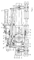
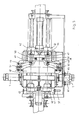
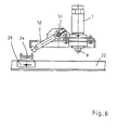
- FIGS. 4 to 8 of the drawing illustrate a central lubrication system for rollers 29 of a chain conveyor 30, the bearings of which can be refilled with lubricant via a lubricating nipple 31.
- Two oppositely arranged lubricant injectors 1 according to FIGS. 1 to 3 are used.
- the chain conveyor 30 consists essentially of a double-T support 32 on which a plurality of support rollers 29 are arranged at a distance from one another.
- the support rollers 29 are each mounted on a central roller pin by means of a bearing 33, the bearing 33 being supplied with lubricant via the grease nipple 31, the roller pin and a transverse bore.
- Each roller 29 carries a chain bracket 34 for a driven endless chain 35 and is also intended to hold a load hook, not shown, for the load.
- a rectangular base plate 38 is fastened on the upper side of the double-T support 32 and carries four support brackets 39 for holding two guide rods 40 arranged parallel to one another and at a distance from the double-T support.
- a holding bracket 44 for an air cylinder 45 is also welded to the slide frame 36, the piston rod 46 of which is provided with a plate 47 on which two levers 48 rest.
- the Levers 48 can be pivoted against the action of a spring 49 running between the holding bracket 44 and the associated lever 48 by the extendable piston rod of the air cylinder. Small rollers 50 on the free ends of the slightly angled levers facilitate interaction with the plate 47.
- a holding plate 67 on the upper frame part of the slide frame 36 and a correspondingly designed holding plate 68, on the lower frame parts, is provided with bearings for two vertically extending axes 51, 52, one each at the level of the injectors 1 and the axes of the support rollers 29 carry rod-shaped drivers 53, 54 which, when the associated levers 48 are pivoted, enter the travel range of the rollers 29 and thus produce the non-positive connection roller-slide for common travel.
- the local assignment of the drivers to the injectors 1 is such that it is possible to place the injector tip 8 with an absolutely precise fit on the associated lubricating nipple 31 of the roller bearing to be lubricated.
- the carriage frame 36 also carries on its upper side a stop 55 which, when the carriage 41 is retracted, interacts with a shock absorber 56 in the manner of a shock absorber to brake its movement and is fastened on the base plate 38 at a corresponding height.
- a 3/2-way valve 58 is first set to passage in a compressed air supply line 59 and compressed air is applied to the air cylinder 45 via a 5/2-way valve 60.
- Its piston rod 46 moves from the position shown in FIG. 4 to the left and thus pivots the levers 48 resting on the plate 47.
- the two axes 51, 52 rotate in such a way that the drivers 53, 54 attached to them move into the path of movement of the support roller 29, as can be seen in FIG .
- the carriage 41 With the movement of the support roller, the carriage 41 is coupled, so that it is slid in the following from the position of FIGS. 4 and 5 to the right on the guide rods 40.
- a proximity switch 61 is now actuated by the slide 41, via which the air supply to the displacement piston 4 of each injector 1 is released by means of a 3/2-way valve 62.
- the injector tip 8 is placed on the respective lubricating nipple 31 of the roller 29 and pressed.
- a 5/2-way valve 63 is then switched, which releases lubricant to the lubricant inlet 10 of the injector via a 3/2-way valve 64, so that the various movements of the control piston and delivery piston of the respective injector are triggered and with a metered amount of lubricant Lubrication of the roller bearing 33 is made from both sides.
- the lubricant pressure to the injectors is first switched off via a further proximity switch 65 and then the air pressure on the injector is ended, so that due to the action of the spring 3 the connection of the injector tip to the lubricated nipple is released.
- the compressed air supply to the air cylinder 45 is then switched off via a delay device, so that the slide 41 is moved back into its starting position according to FIGS. 4 and 5 of the drawing by the return pressure springs 43.
- the impact damper 56 absorbs the kinetic energy.
- the overall device is not only possible for double-sided lubrication - as described - but also for one-sided lubrication alternately for the inside and outside running roller of a chain holder.
Landscapes
- Engineering & Computer Science (AREA)
- General Engineering & Computer Science (AREA)
- Mechanical Engineering (AREA)
- Lubrication Of Internal Combustion Engines (AREA)
- Rolling Contact Bearings (AREA)
- Devices For Conveying Motion By Means Of Endless Flexible Members (AREA)
Applications Claiming Priority (2)
| Application Number | Priority Date | Filing Date | Title |
|---|---|---|---|
| DE19873700782 DE3700782A1 (de) | 1987-01-13 | 1987-01-13 | Schmierstoff-injektor und vorrichtung zur schmierung von wandernden schmierstellen |
| DE3700782 | 1987-01-13 |
Publications (3)
| Publication Number | Publication Date |
|---|---|
| EP0274559A2 true EP0274559A2 (fr) | 1988-07-20 |
| EP0274559A3 EP0274559A3 (en) | 1988-12-07 |
| EP0274559B1 EP0274559B1 (fr) | 1990-09-12 |
Family
ID=6318755
Family Applications (1)
| Application Number | Title | Priority Date | Filing Date |
|---|---|---|---|
| EP87103888A Expired - Lifetime EP0274559B1 (fr) | 1987-01-13 | 1987-03-17 | Injecteur de lubrifiant et dispositif pour lubrifier des points de graissage mobiles |
Country Status (3)
| Country | Link |
|---|---|
| US (1) | US4745990A (fr) |
| EP (1) | EP0274559B1 (fr) |
| DE (2) | DE3700782A1 (fr) |
Cited By (4)
| Publication number | Priority date | Publication date | Assignee | Title |
|---|---|---|---|---|
| BE1003828A3 (fr) * | 1990-02-28 | 1992-06-23 | Gordinne Alain | Appareil destine a huiler ou graisser des chaines a roulements pour convoyeurs. |
| EP0324332B1 (fr) * | 1987-12-14 | 1993-03-24 | "NEUSON" Hydraulik Gesellschaft m.b.H. u. Co. KG | Dispositif de graissage de boulons de chaîne |
| FR2700189A1 (fr) * | 1993-01-06 | 1994-07-08 | Trans Hydro | Installation automatique pour la lubrification d'organes qui se déplacent selon une trajectoire déterminée. |
| FR2700200A1 (fr) * | 1993-01-06 | 1994-07-08 | Trans Hydro | Procédé de commande d'une installation de lubrification. |
Families Citing this family (8)
| Publication number | Priority date | Publication date | Assignee | Title |
|---|---|---|---|---|
| DE4038309A1 (de) * | 1990-11-30 | 1992-06-04 | Voith Gmbh J M | Schmiervorrichtung fuer die schmierung von bolzen einer foerderkette |
| US5186280A (en) * | 1991-05-03 | 1993-02-16 | Mattcheck Donald L | High temperature oven conveyor chain lubrication system |
| GB2358441A (en) * | 2000-01-18 | 2001-07-25 | Jo Bee Liu | Axle bearing lubricating device |
| US9243749B2 (en) | 2013-11-14 | 2016-01-26 | Industrial Manufacturing Company International, LLC | Lubricant injector |
| EP2966013B1 (fr) * | 2014-07-09 | 2019-09-04 | SKF Lubrication Systems France | Injecteur télescopique de lubrification, particulièrement pour un système d'injection de graisse |
| ES2973309T3 (es) * | 2017-07-14 | 2024-06-19 | Lubecore Int Inc | Inyector de lubricante |
| DE102019215231A1 (de) * | 2019-08-21 | 2021-02-25 | Skf Lubrication Systems Germany Gmbh | Schmiermittel-Zumessanordnung |
| DE102024130590A1 (de) * | 2024-10-21 | 2026-04-23 | G. Kraft Maschinenbau Gesellschaft mit beschränkter Haftung | Appliziereinheit für eine Schmiervorrichtung eines Systems zur Schmierung von Schmierstellen einer Gelenkkette sowie Schmiervorrichtung sowie System sowie Doppelendprofiler sowie Verfahren zum Betrieb eines Systems |
Family Cites Families (14)
| Publication number | Priority date | Publication date | Assignee | Title |
|---|---|---|---|---|
| FR1098589A (fr) * | 1954-01-19 | 1955-08-08 | Perfectionnements apportés aux clapets applicables notamment aux distributeurs pour dosage par cloche à air d'un système de graissage central | |
| US2886134A (en) * | 1955-03-16 | 1959-05-12 | Tecalemit Ltd | Lubricating apparatus |
| GB919107A (en) * | 1958-03-20 | 1963-02-20 | Alfred Schmemann | Improvements in or relating to lubricating devices |
| DE1777138U (de) * | 1958-08-09 | 1958-11-06 | Alfred R Dipl Ing Schlosshauer | Vorrichtung zum selbsttaetigen abschmieren wandernder schmierstellen. |
| DE1138952B (de) * | 1960-02-29 | 1962-10-31 | Strojosvit Np | Dosiereinrichtung fuer Schmiermittel, Fluessigkeiten u. dgl. |
| DE1190393B (de) * | 1960-03-11 | 1965-04-01 | King Ltd Geo W | Selbsttaetige Schmiervorrichtung fuer die Laufkatzenraeder eines Foerderers waehrendihrer Bewegung |
| US3135355A (en) * | 1962-03-26 | 1964-06-02 | Olsen Mfg Company | Conveyor lubricating apparatus |
| GB1092602A (en) * | 1964-05-29 | 1967-11-29 | Tecalemit Engineering | Automatic lubricating apparatus for use in lubricating the bearings of rollers or wheels of mobile conveying apparatus |
| US3446314A (en) * | 1965-12-20 | 1969-05-27 | John A Sweeney | Conveyor trolley wheel lubricator |
| GB1272967A (en) * | 1968-07-30 | 1972-05-03 | Tokyo Shibaura Electric Co | Apparatus for supplying lubricant to chain links |
| DE2352868A1 (de) * | 1973-10-22 | 1975-04-30 | Torwegge Maschf F | Abschmiervorrichtung fuer transportketten |
| US3895690A (en) * | 1974-03-12 | 1975-07-22 | Madison Kipp Corp | Lubricator assembly with automatic reset |
| US4067414A (en) * | 1976-08-18 | 1978-01-10 | Funke Ludwig F | Lubricant fitting |
| US4368803A (en) * | 1980-08-07 | 1983-01-18 | Madison-Kipp Corporation | Apparatus for dispensing fluid onto a moving mechanical system |
-
1987
- 1987-01-13 DE DE19873700782 patent/DE3700782A1/de active Granted
- 1987-03-17 EP EP87103888A patent/EP0274559B1/fr not_active Expired - Lifetime
- 1987-03-17 DE DE8787103888T patent/DE3764946D1/de not_active Expired - Fee Related
- 1987-03-31 US US07/032,837 patent/US4745990A/en not_active Expired - Fee Related
Cited By (4)
| Publication number | Priority date | Publication date | Assignee | Title |
|---|---|---|---|---|
| EP0324332B1 (fr) * | 1987-12-14 | 1993-03-24 | "NEUSON" Hydraulik Gesellschaft m.b.H. u. Co. KG | Dispositif de graissage de boulons de chaîne |
| BE1003828A3 (fr) * | 1990-02-28 | 1992-06-23 | Gordinne Alain | Appareil destine a huiler ou graisser des chaines a roulements pour convoyeurs. |
| FR2700189A1 (fr) * | 1993-01-06 | 1994-07-08 | Trans Hydro | Installation automatique pour la lubrification d'organes qui se déplacent selon une trajectoire déterminée. |
| FR2700200A1 (fr) * | 1993-01-06 | 1994-07-08 | Trans Hydro | Procédé de commande d'une installation de lubrification. |
Also Published As
| Publication number | Publication date |
|---|---|
| DE3700782A1 (de) | 1988-07-28 |
| DE3700782C2 (fr) | 1990-01-18 |
| EP0274559B1 (fr) | 1990-09-12 |
| US4745990A (en) | 1988-05-24 |
| EP0274559A3 (en) | 1988-12-07 |
| DE3764946D1 (de) | 1990-10-18 |
Similar Documents
| Publication | Publication Date | Title |
|---|---|---|
| EP0274559B1 (fr) | Injecteur de lubrifiant et dispositif pour lubrifier des points de graissage mobiles | |
| DE20312833U1 (de) | Schmiergerät und ein solches aufweisende Abschmiereinrichtung | |
| EP2537730B1 (fr) | Tampon or couplage pour un véhicule sur rails | |
| DE3716119A1 (de) | Abfuellstation fuer eine kartuschen-fuell- und verschliess-maschine | |
| DE2625850A1 (de) | Geraet zum foerdern von druckfarbe zu einer druckeinrichtung | |
| DE3744795C2 (en) | Lubricant injector for chain conveyor roller bearings | |
| DE3018693A1 (de) | Vorrichtung zum verbinden von markierelementen auf eine fahrbahnoberflaeche und markierelement | |
| DE3123581A1 (de) | Nietvorrichtung | |
| EP1147956A2 (fr) | Dispositif de nettoyage pour surfaces plates | |
| EP0822017A1 (fr) | Système d'entraínement pour une presse d'extrusion de métaux | |
| DE8532752U1 (de) | Kupplungsvorrichtung für Druckmittelleitungen an Walzgerüsten | |
| DE8700570U1 (de) | Schmierstoff-Injektor für eine Vorrichtung zur Schmierung von wandernden Schmierstellen | |
| DE3823122A1 (de) | Bohreinrichtung in einer bohranlage fuer profilstahlstaebe u. dgl. | |
| DE2700604C3 (de) | Vorrichtung zum Auftragen eines Schmiermittels auf den Preßling und/oder die Arbeitsfläche des Umformstempels einer mehrstufigen Warmpresse | |
| DE19530228C1 (de) | Verschiebevorrichtung | |
| DE2610831B2 (de) | Anordnung zum Weiterleiten von Schmiermittel über einen Bewegungsspalt hinweg | |
| DE2401965A1 (de) | Hydraulischer daempfer | |
| DE891819C (de) | Maschine zum Entfernen von in Hohlwerkstuecke von aussen her eingepressten Teilen mittels eines Druckmittels | |
| EP0372176B1 (fr) | Installation de levage hydraulique, en particulier plate-forme de levage à deux ou plusieurs piliers | |
| DE4218578C2 (de) | Vorrichtung zum Auftragen von viskosen Massen | |
| DE965277C (de) | Steuerung fuer eine Druckfluessigkeit, insbesondere zum Schalten von Getrieben fuer Werkzeugmaschinen | |
| DE2701322C2 (de) | Hydraulische Kolben-Zylindereinheit | |
| DE2658230A1 (de) | Stoppvorrichtung fuer haengefoerderer | |
| DE1072120B (de) | Schmiervorrichtung, insbesondere für Kraftfahrzeuge | |
| DE1259239B (de) | Schmiervorrichtung zum selbsttaetigen Abschmieren wandernder Schmierstellen, z. B. der Laufrollen von Foerderketten |
Legal Events
| Date | Code | Title | Description |
|---|---|---|---|
| PUAI | Public reference made under article 153(3) epc to a published international application that has entered the european phase |
Free format text: ORIGINAL CODE: 0009012 |
|
| AK | Designated contracting states |
Kind code of ref document: A2 Designated state(s): BE DE FR GB IT NL SE |
|
| PUAL | Search report despatched |
Free format text: ORIGINAL CODE: 0009013 |
|
| AK | Designated contracting states |
Kind code of ref document: A3 Designated state(s): BE DE FR GB IT NL SE |
|
| 17P | Request for examination filed |
Effective date: 19881104 |
|
| 17Q | First examination report despatched |
Effective date: 19890714 |
|
| GRAA | (expected) grant |
Free format text: ORIGINAL CODE: 0009210 |
|
| AK | Designated contracting states |
Kind code of ref document: B1 Designated state(s): BE DE FR GB IT NL SE |
|
| ET | Fr: translation filed | ||
| GBT | Gb: translation of ep patent filed (gb section 77(6)(a)/1977) | ||
| REF | Corresponds to: |
Ref document number: 3764946 Country of ref document: DE Date of ref document: 19901018 |
|
| ITF | It: translation for a ep patent filed | ||
| ITTA | It: last paid annual fee | ||
| PLBE | No opposition filed within time limit |
Free format text: ORIGINAL CODE: 0009261 |
|
| STAA | Information on the status of an ep patent application or granted ep patent |
Free format text: STATUS: NO OPPOSITION FILED WITHIN TIME LIMIT |
|
| RAP2 | Party data changed (patent owner data changed or rights of a patent transferred) |
Owner name: DE LIMON FLUHME GMBH |
|
| 26N | No opposition filed | ||
| NLT2 | Nl: modifications (of names), taken from the european patent patent bulletin |
Owner name: DE LIMON FLUHME GMBH TE DUESSELDORF, BONDSREPUBLIE |
|
| ITPR | It: changes in ownership of a european patent |
Owner name: CAMBIO RAGIONE SOCIALE;DE LIMON FLUHME GMBH |
|
| REG | Reference to a national code |
Ref country code: FR Ref legal event code: CN |
|
| NLS | Nl: assignments of ep-patents |
Owner name: DE LIMON FLUHME GMBH TE DUESSELDORF, BONDSREPUBLIE |
|
| PGFP | Annual fee paid to national office [announced via postgrant information from national office to epo] |
Ref country code: GB Payment date: 19930303 Year of fee payment: 7 |
|
| PGFP | Annual fee paid to national office [announced via postgrant information from national office to epo] |
Ref country code: FR Payment date: 19930315 Year of fee payment: 7 |
|
| PGFP | Annual fee paid to national office [announced via postgrant information from national office to epo] |
Ref country code: SE Payment date: 19930322 Year of fee payment: 7 |
|
| PGFP | Annual fee paid to national office [announced via postgrant information from national office to epo] |
Ref country code: NL Payment date: 19930331 Year of fee payment: 7 |
|
| PGFP | Annual fee paid to national office [announced via postgrant information from national office to epo] |
Ref country code: BE Payment date: 19930406 Year of fee payment: 7 |
|
| PG25 | Lapsed in a contracting state [announced via postgrant information from national office to epo] |
Ref country code: GB Effective date: 19940317 |
|
| PG25 | Lapsed in a contracting state [announced via postgrant information from national office to epo] |
Ref country code: SE Free format text: LAPSE BECAUSE OF NON-PAYMENT OF DUE FEES Effective date: 19940318 |
|
| PG25 | Lapsed in a contracting state [announced via postgrant information from national office to epo] |
Ref country code: BE Effective date: 19940331 |
|
| PGFP | Annual fee paid to national office [announced via postgrant information from national office to epo] |
Ref country code: DE Payment date: 19940518 Year of fee payment: 8 |
|
| BERE | Be: lapsed |
Owner name: DE LIMON FLUHME G.M.B.H. Effective date: 19940331 |
|
| PG25 | Lapsed in a contracting state [announced via postgrant information from national office to epo] |
Ref country code: NL Effective date: 19941001 |
|
| GBPC | Gb: european patent ceased through non-payment of renewal fee |
Effective date: 19940317 |
|
| NLV4 | Nl: lapsed or anulled due to non-payment of the annual fee | ||
| PG25 | Lapsed in a contracting state [announced via postgrant information from national office to epo] |
Ref country code: FR Effective date: 19941130 |
|
| REG | Reference to a national code |
Ref country code: FR Ref legal event code: ST |
|
| EUG | Se: european patent has lapsed |
Ref document number: 87103888.1 Effective date: 19941010 |
|
| PG25 | Lapsed in a contracting state [announced via postgrant information from national office to epo] |
Ref country code: DE Effective date: 19951201 |
|
| PG25 | Lapsed in a contracting state [announced via postgrant information from national office to epo] |
Ref country code: IT Free format text: LAPSE BECAUSE OF NON-PAYMENT OF DUE FEES;WARNING: LAPSES OF ITALIAN PATENTS WITH EFFECTIVE DATE BEFORE 2007 MAY HAVE OCCURRED AT ANY TIME BEFORE 2007. THE CORRECT EFFECTIVE DATE MAY BE DIFFERENT FROM THE ONE RECORDED. Effective date: 20050317 |