EP0274566B1 - Wiederverwendbarer Schreib-Befähigungs/Sperr-Anzeiger für Videobandkassette - Google Patents
Wiederverwendbarer Schreib-Befähigungs/Sperr-Anzeiger für Videobandkassette Download PDFInfo
- Publication number
- EP0274566B1 EP0274566B1 EP87111742A EP87111742A EP0274566B1 EP 0274566 B1 EP0274566 B1 EP 0274566B1 EP 87111742 A EP87111742 A EP 87111742A EP 87111742 A EP87111742 A EP 87111742A EP 0274566 B1 EP0274566 B1 EP 0274566B1
- Authority
- EP
- European Patent Office
- Prior art keywords
- write enable
- movable means
- recited
- enable device
- further characterized
- Prior art date
- Legal status (The legal status is an assumption and is not a legal conclusion. Google has not performed a legal analysis and makes no representation as to the accuracy of the status listed.)
- Expired - Lifetime
Links
Images


Classifications
-
- G—PHYSICS
- G11—INFORMATION STORAGE
- G11B—INFORMATION STORAGE BASED ON RELATIVE MOVEMENT BETWEEN RECORD CARRIER AND TRANSDUCER
- G11B23/00—Record carriers not specific to the method of recording or reproducing; Accessories, e.g. containers, specially adapted for co-operation with the recording or reproducing apparatus ; Intermediate mediums; Apparatus or processes specially adapted for their manufacture
- G11B23/28—Indicating or preventing prior or unauthorised use, e.g. cassettes with sealing or locking means, write-protect devices for discs
-
- G—PHYSICS
- G11—INFORMATION STORAGE
- G11B—INFORMATION STORAGE BASED ON RELATIVE MOVEMENT BETWEEN RECORD CARRIER AND TRANSDUCER
- G11B23/00—Record carriers not specific to the method of recording or reproducing; Accessories, e.g. containers, specially adapted for co-operation with the recording or reproducing apparatus ; Intermediate mediums; Apparatus or processes specially adapted for their manufacture
- G11B23/28—Indicating or preventing prior or unauthorised use, e.g. cassettes with sealing or locking means, write-protect devices for discs
- G11B23/288—Protecting disks from being written or overwritten
-
- G—PHYSICS
- G11—INFORMATION STORAGE
- G11B—INFORMATION STORAGE BASED ON RELATIVE MOVEMENT BETWEEN RECORD CARRIER AND TRANSDUCER
- G11B23/00—Record carriers not specific to the method of recording or reproducing; Accessories, e.g. containers, specially adapted for co-operation with the recording or reproducing apparatus ; Intermediate mediums; Apparatus or processes specially adapted for their manufacture
- G11B23/02—Containers; Storing means both adapted to cooperate with the recording or reproducing means
- G11B23/04—Magazines; Cassettes for webs or filaments
- G11B23/041—Details
- G11B23/042—Auxiliary features
Definitions
- the present invention relates to write enable device on a tape cassette according to the preamble of claim 1.
- GB-A-1 501 075 US-A-4,041,537 is directed to an audio tape cassette and more particularly to a slide tab which is located in the direct corner of the audio tape cassette - not on the flat rear surface of the tape cassette. Because of this, there is a substantial opening for collection of debris and the like when the slide tab of the GB-Reference is in its upward position as shown in its FIG. 4. Moreover, as shown in its FIG. 3, even in its downward position the slide tab still is not substantially flush with the side surface of the tape cassette.
- the known slide tab as best shown in its FIGS. 1 and 2, must be sandwiched between the cover and base shell halves during assembly and in the final assembled tape cassette product.
- the known slide tab is therefore not fully retained in one of two retainer subhousings, the first being completely formed in the base cover shell and the other completely formed in the cover shell half.
- the assembly of the known tape cassette is significantly complicated and costly because of the requirement of having to sandwich the slide tab during assembly of the cassette.
- said British Reference teaches that it is required to insert a sharp object in the openings in order to move the slide tab between its two positions.
- the consumer In addition to one hand of the consumer having to hold a sharp object to insert into either the opening, the consumer must use its other hand to actually move the slide tab in the opening at the corner of the tape cassette.
- the consumer must use two hands in a very awkward operation to move the slide tab of the reference between its first an second enable and disable positions.
- U.S. Patent No. 4,536,812 shows a read/write tab for a floppy disk.
- the tab merely rests on a planar floppy disc jacket base at a corner thereof.
- the disc Prior to ultrasonically welding the jacket cover to the base, but after inserting the floppy disc and temporarily positioning the cover, the disc is quality tested. If the disc is not up to particular quality standards, the cover must be removed from the base and the disc is discarded. Often, at this stage of production, the tab falls out during handling.
- the write/protect tab must be reinserted in the tab pocket before the cover can be replaced on the base and the testing repeated.
- this type of assembly is time and cost inefficient. The tab of this patent, therefore, is not fully retained in one of the subhousings, as is also true of the British reference.
- An object of the present invention is to provide a write enable tab which is reuseable.
- Another object of the present invention is to provide a reuseable write enable tab for a video cassette without any changes in conventional design and performance specifications.
- Yet another object of the present invention is to provide a write enable tab which remains attached to a tape cassette shell when moved to a write disabled position.
- a further object of the present invention is to provide a write enable tab which is easily moved between two positions, one of which enables writing of a signal onto a tape cassette and the other of which disables writing on the tape cassette.
- the write enable indicator is used on a tape cassette comprising a shell substantially surrounding a signal storage element.
- Retaining means are preferably formed as an integral part of the shell of the tape cassette.
- the movable means preferably includes sliding means with a central body, extensions and internal and external surfaces and movement retarding means formed by a flexible member attached at a first end to the internal surface of the sliding means.
- the retaining means preferably includes first and second walls having respective first and second surfaces facing each other to form a cavity therebetween.
- the first surface of the first wall preferably includes two depressions separated along a first axis.
- the sliding means moves along the first axis from the first position to the second position in response to the external force.
- the flexible member preferably includes a second end projecting into the first and second depressions when the sliding means is in the first and second positions, respectively.
- the present invention is most easily applied to a videotape cassette, such as a VHS standard tape cassette which is conventionally manufactured with a single write enable tab covering a majority of a rectangular opening in the shell of the tape cassette.
- a VHS videotape cassette has a relatively large write enable tab compared to other commonly used signal storage units such as audio tape cassettes and floppy diskettes and has been used for illustration in the drawings.
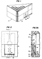
- a write enable indicator is positioned as illustrated in Fig. 1.
- the tape cassette shell 10 substantially surrounds two spools holding magnetic tape (not shown) which acts as a signal storage element.
- a write enable tab 12 is formed of a single piece of moldable material, preferably acetal for lubricity, and preferably having a colour such as red contrasting with the dark colour of the video cassette shell 10. Initially, the write enable tab 12 is positioned as illustrated in Figs. 1, 2 and 3A.
- the write enable tab 12 provides movable means for enabling the recording of a signal on the signal storage element (magnetic tape) in the signal storage unit (cassette) when the movable means is in the first position illustrated in Figs. 1, 2 and 3A.
- the position of the write enable tab 12 may be detected in any conventional manner, including exerting an external force against the tab 12 using a sensor element which will not significantly move the tab 12, due to the relatively small force, e.g., no more than 100 grams, which is typically applied.
- the rear surface 14 of the tape cassette 10 has two walls, an internal wall 16 and an external wall 18, integrally formed as part of the cassette shell 10.
- a narrow cavity 20 is formed between a first surface 22 of the internal wall 16 and a second surface 24 of the external wall 18.
- the walls 16 and 18 form retaining means for retaining the write enable tab 12 in the first and second positions and for permitting the write enable tab to repeatedly move between the first and second positions.
- the internal wall 16 is formed sufficiently close to the external wall 18 so that the internal wall 16 does not intrude on the space allocated for the tape and spools.
- the write enable tab 12 is moved from the first position, illustrated in Fig. 3A to the second position illustrated in Fig. 3D by exerting an external force on the external surface 26 of the write enable tab 12.
- the external force is exerted inwards and upwards on the write enable tab 12 so that the write enable tab 12 leaves the plane of the external wall 18 and moves to the position illustrated in Fig. 3B.
- the write enable tab 12 moves to the position illustrated in Fig. 3C and continues moving until it stops in the second position illustrated in Fig. 3D.
- the cassette shell 10 is formed from two halves 28 and 30, preferably injected molded plastic.
- the lower half or base 28 includes a first depression or opening 32 in the first or inner wall 16 and a large opening 34 defined by edges 36 of the second or outer wall 18.
- the lower half 28 also includes part of a second depression or opening 38 and E-ribs 39 which are formed as part of the inner wall 16 to force the tab outwards until it is flush with the outer wall 18 when it fills the opening 34.
- the opening 38 is further defined by the upper half or cover 30 which also includes a slot 40 in the first wall 16 and stops 41 on the top of the cover 30.
- the write enable tab 12 includes a central body 42 and extensions 44 which are pressed against the second surface 24 (Figs. 3A and 3B) of the second wall 18 by a flexible member 46.
- the flexible member 46 has a first end 48 attached to the internal surface 50 of the central body 42 and a second end 52 which exerts an internal force against the first surface 22 (Fig. 4) of the first wall 16.
- the flexible member 46 is flexed as the write enable tab 12 is moved from the first position in Fig. 3A to the second position Fig. 3D.
- the flexible member 46 projects the second end 52 into the first and second depressions 32 and 38, respectively, thereby holding the write enable tab 12 in place.
- the flexible member 46 withstands the force exerted by the sensor element in the first position (illustrated in Fig. 3A) to enable writing on the video cassette.
- the write enable tab 12 also includes a projection 54 which extends into the slot 40. The corners of the projection 54 may be rounded as illustrated at the top of Fig. 5 or squared as illustrated in the center of Fig. 5.
- the projection 54 and slot 40 form first and second alignment means which direct the write enable tab 12 to move along a first axis between the first and second positions.
- the flexible member 48 exerts the internal force along a second axis which intersects the first axis.
- the external surface 26 of the write enable tab 12 includes a notch 58 or a pinhole 59, or both, which provide engagement means for a stiff object, such as a fingernail in the notch 58 or a ballpoint pen in the pinhole 59, to exert a downward or upward force on the write enable tab 12.
- the stops 41 are included to ensure that the notch 58 or pinhole 59 is exposed when the majority of the write enable tab 12 has been moved to the position illustrated in Fig. 3D, out of the opening 34 and offset from the plane of the external wall 18. This arrangement allows the write enable tab 12 to be easily moved from the second position illustrated in Fig. 3D to the first position illustrated in Fig.
- the notch 58 and pinhole 59 are preferable to a positive projection extending from the external surface 26 of the tab 12, because they reduce the chance of accidental movement by the cassette user.
- the above write enable/disable indicator is particularly suitable for video tape cassettes because it is readily adaptable to existing video tape cassette specifications, easy to manufacture of a moldable material and easy to assemble into the video tape cassette cover and base shell halves for mass production.
- VCR casettes it may be possible to "retrofit" existing VCR casettes by manufacturing inserts which fit into the space left by a broken conventional tab and which include a write enable tab and tracks to hold the tab in place at all four (4) positions illustrated in Figs. 3A-3D.
- the present invention could also be applied to write enable tabs used on audio cassettes.
- commonly used floppy diskettes e.g., 5 1/4 inch diskettes, have a write enable notch which is covered by tape when it is desired to prevent writing on the diskette. If a write enable indicator according to the present invention was used in this application, the tab would be moved to cover the opening to disable writing, instead of being moved out of the opening to disable writing.
Landscapes
- Engineering & Computer Science (AREA)
- Computer Security & Cryptography (AREA)
- Packaging Of Annular Or Rod-Shaped Articles, Wearing Apparel, Cassettes, Or The Like (AREA)
- Rotational Drive Of Disk (AREA)
- Casings For Electric Apparatus (AREA)
Claims (17)
- Schreibbefähigungsvorrichtung an einer Bandkassette (10) zum Ermöglichen und Sperren einer Aufnahme auf dem Band, wobei die Kassette (10) ein Bandkassetten-Gehäuse mit einem ersten Gehäuseteil (30) und einem zweiten Gehäuseteil (28) besitzt, wobei das Bandkassetten-Gehäuse eine längliche Vorderseite, durch die das im Bandkassetten-Gehäuse aufgenommene Band zugänglich ist, eine länglich, der Vorderseite gegenüberliegende, Rückseite (14), sowie Seitenflächen, Oberseite und Boden aufweist, sowie(a) bewegliche Schiebemittel (12), die innerhalb der Kassette (10) aufgenommen sind, um die Aufnahme eines Signals auf das Band zu ermöglichen, wenn das bewegliche Mittel (12) in einer ersten Position ist, und um die Aufnahme eines Signals auf das Band zu verhindern, wenn das bewegliche Mittel (12) in einer zweiten Position ist; und(b) Haltemittel (16,18,32,38( zum Kalten des beweglichen Mittels (12) in der ersten und zweiten Position, die ermöglichen, daß sich das bewegliche Mittel (12) zwischen der ersten und zweiten Position, ansprechend auf eine äußere Kraft, wiederholbar bewegt, wobei das bewegliche Mittel (12) und die Haltemittel (16,18,32,38) an der Rückseite (14) des Kassettengehäuses angeordnet sind, und wobei die Haltemittel (16,18,32,38) einen ersten Hohlraumteil (20) besitzen, das durch eine erste Innenwand (1b) des zweiten Gehäuseteils (28) und eine zweite äußere Wand (18) der Kassette gebildet wird, und ein zweiter Hohlraumteil (20) gebildet wird, und ein zweiter Hohlraumteil (20) durch die erste Innenwand (16) des ersten Gehäuseteils (30) und die zweite Außenwand (18) gebildet wird, und eine einzige Öffnung (34) innerhalb der zweiten Außenwand (18) von einem der Hohlraumteile (20) existiert, und wobei das bewegliche Mittel (12) entlang einer Achse in Querrichtung an der Rückseite des Bandkassettengehäuses zwischen der ersten Befähigungsposition, die im ersten Hohlraumteil (20) angeordnet ist, und der zweiten Sperrposition, die im zweiten Hohlraumteil (20) angeordnet ist, bewegbar ist, dadurch gekennzeichnet, daß das bewegbare Mittel (12) ein flexibles Glied (46) umfasst, das das bewegliche Mittel (12) in eine Richtung weg von der ersten Innenwand (16) in die Öffnung (34), fluchtend mit der Rückseite (14) drückt, wenn das bewegliche Mittel (12) in der ersten Stellung ist, und weg von der ersten Innenwand (16) und gegen die zweite Außenwand (18) drückt, wenn das bewegliche Mittel (12) in der zweiten Stellung ist, wobei die erste Position in einer ersten Ebene und die zweite Position in einer zweiten, parallelen Ebene liegt.
- Schreibbefähigungsvorrichtung nach Anspruch 1, ferner dadurch gekennzeichnet, daß das bewegliche Mittel (12) im wesentlichen an der Rückseite (14) sichtbar ist, wenn es in der ersten Befähigungsstellung im ersten Hohlraumteil (20) des zweiten Gehäuseteils (28) ist, und im wesentlichen an der Rückseite (14) unsichtbar ist, wenn es in der zweiten Sperrposition im zweiten Hohlraumteil (20) des ersten Gehäuseteils (30) ist.
- Schreibbefähigungsvorrichtung nach Anspruch 1, ferner gekennzeichnet durch:
das flexible Glied (46), das mit den Haltemitteln (16,18,32,38) zusammenwirkt, um zu verhindern, daß sich das bewegbare Mittel (12) von der ersten zur zweiten Position bewegt, außer wenn eine äußere Kraft ausgeübt wird. - Schreibbefähigungsvorrichtung nach Anspruch 3, ferner dadurch gekennzeichnet, daß die Haltemittel (16,18,32,38) als integraler Teil des Bandkassetten-Gehäuses ausgebildet sind und einschließlich der ersten Innenwand (16) des Bandkassetten-Gehäuses mit einer ersten Fläche (22),
und daß die zweite Außenwand (18) des Bandkassetten-Gehäuses im wesentlichen parallel zur ersten Wand (16) ausgebildet ist, und eine zweite Fläche (24) aufweist, die der ersten Fläche (22) der ersten Innenwand (16) gegenüberliegt und einen Hohlraum (20) dazwischen ausbildet, wobei das bewegliche Mittel (12) sich zwischen der ersten und zweiten Stellung bewegt, indem es zwischen der ersten (22) und der zweiten (24) Fläche gleitet. - Schreibbefähigungsvorrichtung nach Anspruch 4, ferner dadurch gekennzeichnet, daß das flexible Glied (46) eine innere Kraft entlang einer zweiten, im wesentlichen senkrechten Achse ausübt, um Reibung zwischen den Haltemitteln (16,18,32,38) und dem beweglichen Mittel (12) zu erzeugen, zumindest wenn das bewegliche Mittel (12) in der ersten und zweiten Stellung ist.
- Schreibbefähigungsvorrichtung nach Anspruch 5, ferner dadurch gekennzeichnet, daß die erste Fläche (22) der ersten Innenwand (16) eine erste und zweite Vertiefung (32,38) besitzt, die entlang der ersten Achse voneinander getrennt sind,
und wobei das flexible Glied (46) ein erstes Ende besitzt, das am beweglichen Mittel (12) befestigt ist, sowie ein zweites Ende (52), das in die erste und zweite Vertiefung (32,38) hineinragt, wenn das bewegliche Mittel (12) in der ersten bzw. zweiten Stellung ist. - Schreibbefähigungsvorrichtung nach Anspruch 6, ferner dadurch gekennzeichnet, daß die Öffnung (34) durch Kanten (36) begrenzt ist, die in der zweiten Außenwand (18) ausgebildet sind,
und wobei die erste Innenwand (16) ein erstes Ausrichtungsmittel (40) zum Ausrichten des beweglichen Mittels (12) entlang der ersten Achse umfaßt, und
wobei das bewegliche Mittel (12) ferner einen mittigen Körper (42) einschließt, der eine Innenfläche (50) umfaßt, an der das flexible Glied (46) befestigt ist, und eine Außenfläche (26) besitzt, die durch die Öffnung (34) in der zweiten Außenwand (18) freigelegt wird,
und daß sich Erstreckungen (44) integral mit dem mittigen Körper (42) über die beiden Kanten (36) der zweiten Außenwand (18) auf gegenüberliegenden Seiten des mittigen Körpers (42) erstrecken, und die zweite Fläche (24) der zweiten Außenwand (18) berühren,
und daß ein zweites Ausrichtungsmittel (54) mit dem ersten Ausrichtungsmittel (40) zusammenwirkt, um das bewegliche Mittel (12) entlang der ersten Achse auszurichten. - Schreibbefähigungsvorrichtung nach Anspruch 7, ferner gekennzeichnet dadurch, daß die äußere Kraft durch einen steifen Gegenstand ausgeübt wird,
und wobei das bewegliche Mittel (12) ferner durch Eingriffsmittel (58,59) gekennzeichnet ist, zum Eingriff des steifen Gegenstandes, um die äußere Kraft auf den mittigen Körper (42) zu übertragen. - Schreibbefähigungsvorrichtung nach Anspruch 8, ferner dadurch gekennzeichnet, daß das bewegliche Mittel (12) im wesentlichen die Öffnung (34) in der zweiten Außenwand (18) ausfüllt, wenn das bewegliche Mittel (12) in der ersten Stellung ist, und daß das bewegliche Mittel (12) außer den Eingriffsmitteln (58,59), von der Öffnung (34) in der zweiten Außenwand überwiegend entfernt wird, wenn das bewegliche Mittel (12) in der zweiten Position ist.
- Schreibbefähigungsvorrichtung nach Anspruch 8, ferner dadurch gekennzeichnet, daß das Eingriffsmittel (58,59) ein Stiftloch (59) in der Außenfläche (26) des mittigen Körpers (42) darstellt.
- Schreibbefähigungsvorrichtung nach Anspruch 8, ferner dadurch gekennzeichnet, daß das Eingriffsmittel (58,59) eine Kerbe (58) in der Außenfläche (26) des mittigen Körpers (42) darstellt.
- Schreibbefähigungsvorrichtung nach einem der Ansprüche 1, 2, 7 ferner dadurch gekennzeichnet, daß die einzige Öffnung (34) im zweiten Gehäuseteil (28) ausgebildet ist, um die äußere Kraft auf das bewegliche Mittel (12) auszuüben und dadurch das bewegliche Mittel (12) zwischen der ersten und zweiten Stellung zu bewegen.
- Schreibbefähigungsvorrichtung nach Anspruch 9, ferner dadurch gekennzeichnet, daß die Bandkassette eine Videobandkassette ist.
- Schreibbefähigungsvorrichtung nach Anspruch 1, ferner dadurch gekennzeichnet, daß der erste Hohlraumteil (20) integral als Teil des zweiten Gehäuseteils (28) ausgebildet ist, und daß der zweite Hohlraumteil (20) integral als Teil des ersten Gehäuseteils (30) ausgebildet ist.
- Schreibbefähigungsvorrichtung nach Anspruch 1, ferner dadurch gekennzeichnet, daß das flexible Glied (46) eine innere Kraft entlang einer zweiten, von der ersten Achse abweichende Achse ausübt, und daß Mittel auf den Haltemitteln (16,18,32,38) entlang der ersten Achse ausgebildet sind, um mit dem flexiblen Glied (46) lediglich in der ersten und zweiten Stellung zusammenzuwirken, und wobei das Mittel zum Zusammenwirken zwei Vertiefungen (32,38) umfasst, die entlang der ersten Achse voneinander getrennt sind,
und wobei das flexible Glied (46) mit den Vertiefungen (32,38) zusammenwirkt, um zu verhindern, daß sich das bewegliche Mittel (12) von der ersten zur zweiten Stellung bewegt, außer wenn die externe Kraft ausgeübt wird. - Schreibbefähigungsvorrichtung nach Anspruch 1, bei der das bewegliche Mittel (12) aus Acetal konstruiert ist.
- Schreibbefähigungsvorrichtung nach Anspruch 1, bei der das Bandkassetten-Gehäuse eine erste Farbe aufweist, und daß das bewegliche Mittel (12) eine zweite, kontrastierende Farbe besitzt.
Priority Applications (1)
| Application Number | Priority Date | Filing Date | Title |
|---|---|---|---|
| AT87111742T ATE100623T1 (de) | 1987-01-16 | 1987-08-13 | Wiederverwendbarer schreib-befaehigungs/sperranzeiger fuer videobandkassette. |
Applications Claiming Priority (2)
| Application Number | Priority Date | Filing Date | Title |
|---|---|---|---|
| US3761 | 1987-01-16 | ||
| US07/003,761 US5184255A (en) | 1987-01-16 | 1987-01-16 | Video tape cassette with a reusable recording enable/disable slide tab |
Publications (3)
| Publication Number | Publication Date |
|---|---|
| EP0274566A2 EP0274566A2 (de) | 1988-07-20 |
| EP0274566A3 EP0274566A3 (en) | 1989-08-23 |
| EP0274566B1 true EP0274566B1 (de) | 1994-01-19 |
Family
ID=21707457
Family Applications (1)
| Application Number | Title | Priority Date | Filing Date |
|---|---|---|---|
| EP87111742A Expired - Lifetime EP0274566B1 (de) | 1987-01-16 | 1987-08-13 | Wiederverwendbarer Schreib-Befähigungs/Sperr-Anzeiger für Videobandkassette |
Country Status (14)
| Country | Link |
|---|---|
| US (1) | US5184255A (de) |
| EP (1) | EP0274566B1 (de) |
| JP (1) | JPS63187485A (de) |
| KR (1) | KR910002497B1 (de) |
| CN (1) | CN1016018B (de) |
| AR (1) | AR241344A1 (de) |
| AT (1) | ATE100623T1 (de) |
| AU (1) | AU605808B2 (de) |
| BR (1) | BR8704206A (de) |
| CA (1) | CA1304158C (de) |
| DE (1) | DE3788866T2 (de) |
| GR (1) | GR871080B (de) |
| MX (1) | MX169146B (de) |
| NZ (1) | NZ222340A (de) |
Families Citing this family (9)
| Publication number | Priority date | Publication date | Assignee | Title |
|---|---|---|---|---|
| JP2730228B2 (ja) * | 1989-12-06 | 1998-03-25 | ソニー株式会社 | テープカセット |
| JP2979613B2 (ja) * | 1990-09-20 | 1999-11-15 | ソニー株式会社 | テープカセット |
| DE9110112U1 (de) * | 1991-08-16 | 1991-11-14 | BASF Magnetics GmbH, 6800 Mannheim | Kassette mit Aufzeichnungsträger, insbesondere Magnetbandkassette |
| KR200149470Y1 (ko) * | 1993-09-28 | 1999-06-15 | 장용균 | 비디오 테이프 카세트의 케이스 내부구조 |
| JPH07111062A (ja) * | 1993-10-14 | 1995-04-25 | Sony Corp | テープカートリッジにおける誤記録防止機構 |
| US5828534A (en) * | 1995-06-06 | 1998-10-27 | Lou; Eddie Y. S. | Write enable device |
| US6031675A (en) * | 1995-08-31 | 2000-02-29 | Sony Corporation | Recording medium device provided with erroneous recording prevention mechanism |
| US7142386B1 (en) * | 2005-08-26 | 2006-11-28 | Tandberg Storage Asa | Tape drive with microswitch protector |
| JP6767252B2 (ja) * | 2016-12-09 | 2020-10-14 | 株式会社ワコム | 電子ペン |
Family Cites Families (33)
| Publication number | Priority date | Publication date | Assignee | Title |
|---|---|---|---|---|
| US3320030A (en) * | 1963-06-24 | 1967-05-16 | Allied Chem | Production of sulfuryl fluoride |
| US3826489A (en) * | 1971-01-25 | 1974-07-30 | Data Packaging Corp | Tape cassette |
| US3848265A (en) * | 1972-07-31 | 1974-11-12 | Information Terminals Corp | Tape cassette |
| JPS49126014A (de) * | 1973-04-05 | 1974-12-03 | ||
| US3828363A (en) * | 1973-05-09 | 1974-08-06 | S Somers | Cassette containing two hubs carrying a magnetic tape, for use with recording/reproducing apparatus |
| JPS50119322A (de) * | 1974-03-05 | 1975-09-18 | ||
| DE2559762C2 (de) * | 1974-10-21 | 1983-06-16 | Olympus Optical Co., Ltd., Tokyo | Anordnung zur Steuerung von Betriebsarten eines Tonbandgerätes |
| US3950786A (en) * | 1975-02-07 | 1976-04-13 | K/Tronic, Inc. | Magnetic tape cassette with sliding door to inhibit recording |
| JPS5540624Y2 (de) * | 1975-04-17 | 1980-09-22 | ||
| JPS5438190Y2 (de) * | 1975-04-22 | 1979-11-14 | ||
| US4173319A (en) * | 1975-12-13 | 1979-11-06 | Victor Company Of Japan, Limited | Magnetic tape cassette |
| AT356921B (de) * | 1978-07-13 | 1980-06-10 | Philips Nv | Magnetbandkassette |
| JPS5698759A (en) * | 1979-12-29 | 1981-08-08 | Sony Corp | Recording and reproducing device |
| JPS6048343B2 (ja) * | 1980-01-12 | 1985-10-26 | 日立工機株式会社 | 印字装置の印字タイミング制御法 |
| US4320421A (en) * | 1980-05-27 | 1982-03-16 | International Business Machines Corporation | Rotary actuator for file protect function |
| US4320422A (en) * | 1980-05-27 | 1982-03-16 | International Business Machines Corporation | File protect sleeve |
| ATE18617T1 (de) * | 1980-07-28 | 1986-03-15 | Hitachi Maxell | Magnetbandkassette. |
| WO1981001907A1 (en) * | 1980-08-05 | 1981-07-09 | Budapesti Radiotechnikai Gyar | Indicator device for cassettes loaded with magnetical information carrier |
| JPS6343643Y2 (de) * | 1980-12-16 | 1988-11-14 | ||
| US4399481A (en) * | 1981-04-13 | 1983-08-16 | Loranger Manufacturing Company | Lockout device for tape cassette |
| JPS6319976Y2 (de) * | 1981-06-04 | 1988-06-03 | ||
| JPS5924479A (ja) * | 1982-08-02 | 1984-02-08 | Fuji Photo Film Co Ltd | 磁気デイスクカ−トリツジ |
| US4496999A (en) * | 1982-09-10 | 1985-01-29 | Espin Mario W | Video tape cassette and device therefor |
| JPH0630184B2 (ja) * | 1982-11-22 | 1994-04-20 | 富士写真フイルム株式会社 | 磁気テープカセット及び該カセットの操作方法 |
| US4549240A (en) * | 1982-11-26 | 1985-10-22 | Verbatim Corporation | Write protection device |
| JPS59168876U (ja) * | 1983-04-22 | 1984-11-12 | 富士写真フイルム株式会社 | 磁気デイスクカ−トリツジ |
| US4564871A (en) * | 1983-12-27 | 1986-01-14 | Minnesota Mining And Manufacturing Company | Automatic record-lockout mechanism |
| JPS6132285A (ja) * | 1984-07-23 | 1986-02-14 | Sony Corp | 磁気テ−プカセツト |
| JPS6133290U (ja) * | 1984-07-28 | 1986-02-28 | ソニー株式会社 | 記録媒体収容カセツト |
| JPS61105983U (de) * | 1984-12-17 | 1986-07-05 | ||
| US4665456A (en) * | 1985-04-29 | 1987-05-12 | Minnesota Mining And Manufacturing Company | Reusable record tab for videotape cassette |
| US4685017A (en) * | 1985-06-11 | 1987-08-04 | Shape Inc. | Write/protect tab assembly for a floppy disc jacket and method for assembling same |
| US4618060A (en) * | 1985-11-07 | 1986-10-21 | Tarter Norman D | Floppy disc casing with optional write-protect capability |
-
1987
- 1987-01-16 US US07/003,761 patent/US5184255A/en not_active Expired - Fee Related
- 1987-07-06 CA CA000541334A patent/CA1304158C/en not_active Expired - Fee Related
- 1987-07-07 AR AR87308091A patent/AR241344A1/es active
- 1987-07-09 GR GR871080A patent/GR871080B/el unknown
- 1987-07-24 MX MX007491A patent/MX169146B/es unknown
- 1987-07-31 KR KR1019870008412A patent/KR910002497B1/ko not_active Expired
- 1987-08-13 BR BR8704206A patent/BR8704206A/pt unknown
- 1987-08-13 AT AT87111742T patent/ATE100623T1/de not_active IP Right Cessation
- 1987-08-13 EP EP87111742A patent/EP0274566B1/de not_active Expired - Lifetime
- 1987-08-13 DE DE87111742T patent/DE3788866T2/de not_active Expired - Fee Related
- 1987-09-09 CN CN87106223A patent/CN1016018B/zh not_active Expired
- 1987-10-19 JP JP62261893A patent/JPS63187485A/ja active Pending
- 1987-10-29 NZ NZ222340A patent/NZ222340A/xx unknown
- 1987-12-15 AU AU82550/87A patent/AU605808B2/en not_active Ceased
Also Published As
| Publication number | Publication date |
|---|---|
| US5184255A (en) | 1993-02-02 |
| AR241344A1 (es) | 1992-05-29 |
| CA1304158C (en) | 1992-06-23 |
| EP0274566A2 (de) | 1988-07-20 |
| AU8255087A (en) | 1988-07-21 |
| CN87106223A (zh) | 1988-07-27 |
| DE3788866D1 (de) | 1994-03-03 |
| MX169146B (es) | 1993-06-23 |
| AU605808B2 (en) | 1991-01-24 |
| NZ222340A (en) | 1991-02-26 |
| KR880009366A (ko) | 1988-09-14 |
| ATE100623T1 (de) | 1994-02-15 |
| CN1016018B (zh) | 1992-03-25 |
| JPS63187485A (ja) | 1988-08-03 |
| GR871080B (en) | 1987-11-12 |
| KR910002497B1 (ko) | 1991-04-23 |
| EP0274566A3 (en) | 1989-08-23 |
| DE3788866T2 (de) | 1994-05-05 |
| BR8704206A (pt) | 1988-08-02 |
Similar Documents
| Publication | Publication Date | Title |
|---|---|---|
| EP0164647B1 (de) | Kassette für Aufzeichnungsplatte | |
| JPS6333830Y2 (de) | ||
| US5757764A (en) | Disc cartridge having a write protect operating portion disposed within the cartridge body | |
| US5367422A (en) | Disc cartridge having mistaken recording inhibiting mechanism | |
| JPH0268374U (de) | ||
| US4734812A (en) | Tape cartridge with erasure-preventing indicator plug | |
| EP0209892A2 (de) | Plattenkassette mit einer Reinigungsvorrichtung | |
| US5184255A (en) | Video tape cassette with a reusable recording enable/disable slide tab | |
| US5196978A (en) | Cartridge case | |
| US4660105A (en) | Cassette recording or non-recording indicating mechanism | |
| US5748420A (en) | Ultra-high capacity removable media cartridge configured to prevent insertion in a conventional floppy disk drive | |
| US5886859A (en) | Magnetic disc cartridge | |
| US4743993A (en) | Plate spring assembly for a magnetic recording disk cartridge | |
| US5793583A (en) | Magnetic disk cartridge | |
| JP2615591B2 (ja) | ディスクカセット | |
| JP2926015B2 (ja) | カートリッジ | |
| JPH0739102Y2 (ja) | 3.5インチ用光ディスクカートリッジ | |
| US6421203B1 (en) | Magnetic tape cassette slider lock mechanism with tapered surfaces and coil spring bias | |
| JP4416353B2 (ja) | ディスクカートリッジ | |
| JPH0341316Y2 (de) | ||
| JP2555012Y2 (ja) | ディスクカートリッジ | |
| JP3226941B2 (ja) | デイスクカートリツジ収納ケース | |
| JPH0416308Y2 (de) | ||
| JPH0320954Y2 (de) | ||
| JPH0138794Y2 (de) |
Legal Events
| Date | Code | Title | Description |
|---|---|---|---|
| PUAI | Public reference made under article 153(3) epc to a published international application that has entered the european phase |
Free format text: ORIGINAL CODE: 0009012 |
|
| AK | Designated contracting states |
Kind code of ref document: A2 Designated state(s): AT BE CH DE ES FR GB IT LI NL SE |
|
| PUAL | Search report despatched |
Free format text: ORIGINAL CODE: 0009013 |
|
| AK | Designated contracting states |
Kind code of ref document: A3 Designated state(s): AT BE CH DE ES FR GB IT LI NL SE |
|
| 17P | Request for examination filed |
Effective date: 19900222 |
|
| 17Q | First examination report despatched |
Effective date: 19910424 |
|
| GRAA | (expected) grant |
Free format text: ORIGINAL CODE: 0009210 |
|
| ITF | It: translation for a ep patent filed | ||
| AK | Designated contracting states |
Kind code of ref document: B1 Designated state(s): AT BE CH DE ES FR GB IT LI NL SE |
|
| PG25 | Lapsed in a contracting state [announced via postgrant information from national office to epo] |
Ref country code: SE Effective date: 19940119 Ref country code: NL Effective date: 19940119 Ref country code: LI Effective date: 19940119 Ref country code: CH Effective date: 19940119 Ref country code: BE Effective date: 19940119 Ref country code: AT Effective date: 19940119 |
|
| REF | Corresponds to: |
Ref document number: 100623 Country of ref document: AT Date of ref document: 19940215 Kind code of ref document: T |
|
| REF | Corresponds to: |
Ref document number: 3788866 Country of ref document: DE Date of ref document: 19940303 |
|
| REG | Reference to a national code |
Ref country code: CH Ref legal event code: PL |
|
| PG25 | Lapsed in a contracting state [announced via postgrant information from national office to epo] |
Ref country code: ES Free format text: LAPSE BECAUSE OF FAILURE TO SUBMIT A TRANSLATION OF THE DESCRIPTION OR TO PAY THE FEE WITHIN THE PRESCRIBED TIME-LIMIT Effective date: 19940430 |
|
| ET | Fr: translation filed | ||
| NLV1 | Nl: lapsed or annulled due to failure to fulfill the requirements of art. 29p and 29m of the patents act | ||
| PLBE | No opposition filed within time limit |
Free format text: ORIGINAL CODE: 0009261 |
|
| STAA | Information on the status of an ep patent application or granted ep patent |
Free format text: STATUS: NO OPPOSITION FILED WITHIN TIME LIMIT |
|
| 26N | No opposition filed | ||
| PGFP | Annual fee paid to national office [announced via postgrant information from national office to epo] |
Ref country code: GB Payment date: 19950807 Year of fee payment: 9 |
|
| PGFP | Annual fee paid to national office [announced via postgrant information from national office to epo] |
Ref country code: DE Payment date: 19950814 Year of fee payment: 9 |
|
| PGFP | Annual fee paid to national office [announced via postgrant information from national office to epo] |
Ref country code: FR Payment date: 19950817 Year of fee payment: 9 |
|
| PG25 | Lapsed in a contracting state [announced via postgrant information from national office to epo] |
Ref country code: GB Effective date: 19960813 |
|
| GBPC | Gb: european patent ceased through non-payment of renewal fee |
Effective date: 19960813 |
|
| PG25 | Lapsed in a contracting state [announced via postgrant information from national office to epo] |
Ref country code: FR Effective date: 19970430 |
|
| PG25 | Lapsed in a contracting state [announced via postgrant information from national office to epo] |
Ref country code: DE Effective date: 19970501 |
|
| REG | Reference to a national code |
Ref country code: FR Ref legal event code: ST |
|
| PG25 | Lapsed in a contracting state [announced via postgrant information from national office to epo] |
Ref country code: IT Free format text: LAPSE BECAUSE OF NON-PAYMENT OF DUE FEES Effective date: 20050813 |