EP0274594A2 - Appareil de nettoyage pour véhicules - Google Patents
Appareil de nettoyage pour véhicules Download PDFInfo
- Publication number
- EP0274594A2 EP0274594A2 EP87116293A EP87116293A EP0274594A2 EP 0274594 A2 EP0274594 A2 EP 0274594A2 EP 87116293 A EP87116293 A EP 87116293A EP 87116293 A EP87116293 A EP 87116293A EP 0274594 A2 EP0274594 A2 EP 0274594A2
- Authority
- EP
- European Patent Office
- Prior art keywords
- baskets
- curtains
- scrubbing
- basket
- phase
- Prior art date
- Legal status (The legal status is an assumption and is not a legal conclusion. Google has not performed a legal analysis and makes no representation as to the accuracy of the status listed.)
- Withdrawn
Links
- 238000005201 scrubbing Methods 0.000 title claims abstract description 27
- 230000010355 oscillation Effects 0.000 claims abstract description 10
- 230000003534 oscillatory effect Effects 0.000 claims abstract description 5
- 230000033001 locomotion Effects 0.000 claims description 11
- 230000008093 supporting effect Effects 0.000 claims description 4
- 238000004140 cleaning Methods 0.000 claims description 2
- 230000001419 dependent effect Effects 0.000 claims 1
- 229920000136 polysorbate Polymers 0.000 abstract 1
- 238000003466 welding Methods 0.000 description 8
- 230000003247 decreasing effect Effects 0.000 description 1
- 238000000926 separation method Methods 0.000 description 1
Images



Classifications
-
- B—PERFORMING OPERATIONS; TRANSPORTING
- B60—VEHICLES IN GENERAL
- B60S—SERVICING, CLEANING, REPAIRING, SUPPORTING, LIFTING, OR MANOEUVRING OF VEHICLES, NOT OTHERWISE PROVIDED FOR
- B60S3/00—Vehicle cleaning apparatus not integral with vehicles
- B60S3/04—Vehicle cleaning apparatus not integral with vehicles for exteriors of land vehicles
-
- Y—GENERAL TAGGING OF NEW TECHNOLOGICAL DEVELOPMENTS; GENERAL TAGGING OF CROSS-SECTIONAL TECHNOLOGIES SPANNING OVER SEVERAL SECTIONS OF THE IPC; TECHNICAL SUBJECTS COVERED BY FORMER USPC CROSS-REFERENCE ART COLLECTIONS [XRACs] AND DIGESTS
- Y10—TECHNICAL SUBJECTS COVERED BY FORMER USPC
- Y10S—TECHNICAL SUBJECTS COVERED BY FORMER USPC CROSS-REFERENCE ART COLLECTIONS [XRACs] AND DIGESTS
- Y10S15/00—Brushing, scrubbing, and general cleaning
- Y10S15/02—Car cleaning plants
Definitions
- This invention relates to scrubbing apparatus for cleaning the exterior surfaces of an automobile or other motor vehicle.
- the present invention represents an improvement over the scrubbing apparatus shown, described and claimed in U. S. Patent No. 3,859,686 issued January 14, 1975 to Donald E. Breish and assigned to to the assignee of the present application.
- An important object of the invention is to provide a scrubbing apparatus of the general type shown and described in the aforesaid U.S. Patent No. 3,859,686 but in which the tendency of the apparatus to twist in response to torsional reaction forces developed therein is eliminated.
- This is accomplished by so arranging the oscillatory curtain baskets, the drive, and the linkages, that the width of the curtains moving in opposite lengthwise directions are equal on each side of the lengthwise axis of the apparatus.
- three curtain baskets are provided, an inner basket and two outer baskets. The curtains of the inner baskets. The oscillating movement of the inner basket is out of phase with that of the two outer baskets which oscillate in phase relative to each other.
- Another object is to provide a scrubbing apparatus as aforesaid in which the drive for the oscillating motion of the baskets is supplied by a single motor.
- a further object is to provide a scrubbing apparatus as aforesaid in which the single motor, through a pair of crank arms and connecting linkages, applies thrust forces at a point located below, rather than above, the pivot axis of the baskets thereby reducing the height of the apparatus.
- Yet another object is to provide a scrubbing apparatus of the general type shown in the aforesaid '686 patent which is so constructed as to have a reduced net impact on an upstanding auto antenna.
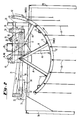
- Fig. 3 is a diagrammatic perspective view of a preferred embodiment of the apparatus of the present invention.
- the apparatus comprises three baskets of curtains, an inner or center basket 10 and two end or outer baskets 40 and 70.
- the inner basket 10 contains a series of curtain strips 11 while the outer baskets 40 and 70 each contain a series of curtain strips identified 41 and 71, respectively. While only a single split curtain for each basket is shown in Fig. 3, each basket contains a series of split curtains spaced in the lengthwise direction of the apparatus, as is illustrated diagrammatically in Fig. 2.
- each of the baskets 10, 40 and 70 is formed by a pair of arcuate angle members identified 12, 42 and 72, respectively. From these arcuate members the split curtains are suspended.
- the arcuate angle members of each pair are connected by cross bars identified 13, 43 and 73 respectively. Some of these cross bars are secured, as by welding, to the lower ends of pairs of angle members identified 14, 44 and 74.
- Angle members 14, 44, 74 extend upwardly in a converging fashion to form for each basket a pair of A-frame structures. At the apex, each pair of A-frame structures is secured, as by welding to a pair of oscillating levers identified 15, 45 and 75 respectively.
- Each of the pairs of oscillating levers 15, 45, 75 is secured, as by welding, to one of three rods 16, 46, 76 which extend transversely of the apparatus and which are journalled in pillow blocks 36, not shown in Fig. 3 but shown in Figs. 1 and 2.
- the pillow blocks 36 are supported on a series of transverse and longitudinal C-shaped frame members or beams not shown in Fig. 3 but shown in Figs. 1 and 2 identified 30 and 35 respectively.
- Pivotally secured to a lower point on one lever of each pair of oscillating levers is one end of a generally horizontal longitudinally-extending reciprocating drive bar identified 17, 47, 77 respectively.
- the other end of each of the drive bars is pivotally secured to the lower end of a generally vertical oscillating lever identified 18, 48, 78 respectively.
- the upper end of the each of the oscillating levers 18, 48, 78 is fixed, as by welding, to a transversely extending bar.
- Lever 18 is connected to the shorter bar 19.
- Levers 78 and 48 are connected to the longer bar 79.
- drive lever 20 Also connected, as by welding, to the shorter bar 19 is the upper end of a drive lever 20.
- the lower end of drive lever 20 is pivotally connected to one end of a first generally-horizontal longitudinally-extending reciprocating connecting link 21.
- the other end of link 21 is pivotally connected to crank 22 which is driven rotationally by motor 50 through a gear box 51.
- drive lever 80 Connected, as by welding, to the longer bar 79 is the upper end of a drive lever 80.
- the lower end of drive lever 80 is pivotally connected to one end of a second generally-horizontal longitudinally-extending reciprocating connecting link 81.
- the other end of link 81 is pivotally connected to crank 82 driven rotationally by the motor 50 through the gear box 51.
- the curtains 11 of the inner or center basket 10 are preferably twice as wide as the curtains 41 and 71 of the outer baskets 40, 70.
- the sum of the widths of the outer curtains 41, 71 is equal to the width of the inner curtain 11.
- each of the curtains 11 is four feet wide while each of the curtains 41, 71 is two feet wide.
- All three curtain baskets, 10, 40, 70 are driven in a oscillating manner.
- the outer baskets 40 and 70 oscillate in phase.
- the inner basket 10 is driven out of phase with the outer baskets.
- the inner basket 10 is driven 90° out of phase with the two outer baskets 40, 70.
- the out-of-phase relationship is illustrated diagrammatically in Figs. 4A, 4B, 4C, 4D which will be described later.
- cranks 22 and 82 are,in the preferred embodiment, driven rotationally 90° out of phase.
- crank 22 is shown in the 0° or 12:00 o'clock position while crank 82 is in the 90° or three o'clock position.
- the connecting links 21 and 81 are driven in a reciprocating manner.
- This drives the levers 20 and 80 in an oscillating manner.
- the levers 20 and 80 are secured, as by welding, to the rods 19 and 79, each of these rods 19, 79 oscillates on its own axis. Oscillation of rods 19, 79, causes levers 18, 48 and 78 to oscillate and to drive bars 17, 47, 77 in a reciprocating manner.
- This drives the pairs of levers 15, 14, 45, 75 in an oscillating manner about the pivot bars 16, 46, 76 and drives the baskets 10, 40, 70 in a corresponding oscillating manner about bars 16, 46, 76.
- crank 22 which drives center basket 10 is shown in the zero or twelve o'clock position while crank 82 which drives the outer baskets 40, 70 is shown in the 90° or three o'clock position. This corresponds to the phase position shown in Fig. 3.
- Fig. 4A as in Fig. 3, the center basket 10 is at its lower position while the outer baskets 40, 70 are at an upper limit of their pendulum-like swings. The position shown in Fig.
- FIG. 4A may be assumed to be the position occupied at the start of the first quarter of a 360° cycle.
- Fig. 4B shows the position at the start of the second quarter.
- the inner basket 10 has now been swung to its upper limit while the outer baskets 40, 70 have been swung back down to their lower positions.
- Fig. 4C illustrates the position of the start of the third quarter.
- the outer baskets 40, 70 have now been swung to their upper limits while the inner basket 10 has returned back down to its lower position.
- Fig. 4D which illustrates the position at the start of the fourth quarter, the inner basket 10 has swung up to its upper limit while the outer baskets 40, 70 have returned back down to their or lower positions.
- the oscillating movement of the curtain baskets 10, 40, 70 is such that in the first and third quarter of the full cycle, curtains are moving in opposite directions while in the second and fourth quarters all curtains are moving in the same direction but the center curtains are lagging behind the outer curtains.
- the reaction forces developed in the apparatus resulting from curtains being dragged lengthwise over the car, whether in the same or opposite directions as that in which the car is moving, are at all times equal on opposite sides of the longitudinal center axis of the apparatus.
- no torsional reaction forces are generated, and the apparatus of the invention avoids the development of those forces which cause the apparatus to vibrate and shake.
- the apparatus of the present invention is driven by a single motor having two crank arms whose phase relationship, relative to each other, remains unchanged during operation.
- single motor avoids the problem of maintaining proper phase relationship which would be the case if more than one drive motor were used.
- An additional advantage which results from the curtain arrangement of the present application is that the antenna on the car is frequently so positioned that it passes through the separation between an outer curtain and the center curtain and that, as a result, the antenna is subjected to a substantially decreased knock-over force.
- crank arms 22, 82 are 90° out of phase and the inner curtain basket 10 is driven in an oscillatory manner 90° out-of-phase relative to the outer curtain baskets 40, 70.
- the crank arms 22, 82 could, however, be positioned at a different relative angle, such for example as 180°, in which case the inner curtain basket 10 would be driven 180° out of phase relative to the outer baskets 40, 70.
- FIG. 3 The drawing in Fig. 3 is adequate for an understanding of the operation of the apparatus of the present invention.
- the supporting frame members have, for simplicity, been omitted from Fig. 3. These frame members are however shown in Figs. 1 and 2 and will now be briefly described.
- the curtain baskets are supported on an open frame through which the auto mobile to be washed passes.
- the auto may be assumed to move from right to left.
- the open frame includes vertical posts 91 which support at their upper ends two longitudinal beams 92 and two transverse beams 93 defining a rectangular structure.
- Supported on the longitudinal beams 92 are three C-shaped beams 30 which extend transversely across the structure.
- each of the beams 35 Supported on each of the beams 35 are one or more pillow blocks 36 in which are journalled bars 16, 46, 76, 79 and 19. Eleven such pillow blocks 36 are shown in Fig. 1. It is believed that Figs. 1 and 2 together with the foregoing description provides a sufficient understanding as to the manner in which the drive motor, the linkages and the curtain baskets are mounted on the open frame for oscillating out-of-phase movement.
Landscapes
- Engineering & Computer Science (AREA)
- Mechanical Engineering (AREA)
- Treatment Of Fiber Materials (AREA)
Applications Claiming Priority (2)
| Application Number | Priority Date | Filing Date | Title |
|---|---|---|---|
| US07/003,130 US4744122A (en) | 1987-01-14 | 1987-01-14 | Scrubbing apparatus for vehicles |
| US3130 | 1993-01-12 |
Publications (2)
| Publication Number | Publication Date |
|---|---|
| EP0274594A2 true EP0274594A2 (fr) | 1988-07-20 |
| EP0274594A3 EP0274594A3 (fr) | 1989-10-11 |
Family
ID=21704313
Family Applications (1)
| Application Number | Title | Priority Date | Filing Date |
|---|---|---|---|
| EP87116293A Withdrawn EP0274594A3 (fr) | 1987-01-14 | 1987-11-05 | Appareil de nettoyage pour véhicules |
Country Status (3)
| Country | Link |
|---|---|
| US (1) | US4744122A (fr) |
| EP (1) | EP0274594A3 (fr) |
| AU (1) | AU602026B2 (fr) |
Families Citing this family (4)
| Publication number | Priority date | Publication date | Assignee | Title |
|---|---|---|---|---|
| US5148570A (en) * | 1991-02-28 | 1992-09-22 | Bivens Winchester Corporation | Car wash system |
| US5813076A (en) * | 1996-04-29 | 1998-09-29 | Belanger, Inc. | Curtain-style vehicle laundry device |
| US20020184722A1 (en) | 2001-06-12 | 2002-12-12 | Charles M. Kaady | Overhead washer for automatic car washes |
| US7784140B2 (en) * | 2008-02-19 | 2010-08-31 | Motor City Wash Works, Inc. | Vehicle wash mitter assembly with offset racks |
Family Cites Families (11)
| Publication number | Priority date | Publication date | Assignee | Title |
|---|---|---|---|---|
| AT261423B (de) * | 1965-12-22 | 1968-04-25 | Heinrich Dipl Ing Wuester | Vorrichtung zum automatischen Reinigen von Kraftfahrzeugen |
| US3510898A (en) * | 1968-04-16 | 1970-05-12 | Seizo Tatara | Automatic washing apparatus for car body and the like |
| US3499180A (en) * | 1968-06-12 | 1970-03-10 | Sherman Car Wash Equip Co | Scrubbing apparatus for vehicles |
| US3683441A (en) * | 1970-01-13 | 1972-08-15 | Richard H Fromme | Vehicle cleaning device |
| US3765043A (en) * | 1971-04-30 | 1973-10-16 | J Lesser | Automatic car wash |
| US3862460A (en) * | 1973-03-19 | 1975-01-28 | Elden J Rockafellow | Car wash apparatus |
| US3859686A (en) * | 1973-05-23 | 1975-01-14 | Sherman Car Wash Equip Co | Scrubbing apparatus for vehicles |
| DE2437363A1 (de) * | 1973-08-09 | 1975-02-20 | Lyle Beverly Evans | Fahrzeugwaschanlage |
| US4164053A (en) * | 1974-04-12 | 1979-08-14 | Shelstad Richard J | Vehicle washing apparatus |
| US4057866A (en) * | 1976-10-01 | 1977-11-15 | Belanger, Inc. | Apparatus for washing and drying motor vehicles |
| US4096600A (en) * | 1977-03-11 | 1978-06-27 | Belanger James A | Friction curtain apparatus |
-
1987
- 1987-01-14 US US07/003,130 patent/US4744122A/en not_active Expired - Lifetime
- 1987-11-05 EP EP87116293A patent/EP0274594A3/fr not_active Withdrawn
- 1987-11-20 AU AU81473/87A patent/AU602026B2/en not_active Ceased
Also Published As
| Publication number | Publication date |
|---|---|
| AU602026B2 (en) | 1990-09-27 |
| AU8147387A (en) | 1988-07-21 |
| EP0274594A3 (fr) | 1989-10-11 |
| US4744122A (en) | 1988-05-17 |
Similar Documents
| Publication | Publication Date | Title |
|---|---|---|
| US4096600A (en) | Friction curtain apparatus | |
| US3647068A (en) | Carrying members for deforming web screens | |
| US3499180A (en) | Scrubbing apparatus for vehicles | |
| US3859686A (en) | Scrubbing apparatus for vehicles | |
| EP0274594A2 (fr) | Appareil de nettoyage pour véhicules | |
| GB1601590A (en) | Mechanism for effecting motion of a member in a prescribed path | |
| US4505812A (en) | Sieve screen deck | |
| WO2004030781A1 (fr) | Appareil d'attraction foraine | |
| DE10003172C1 (de) | Siebvorrichtung und Verfahren zum Betreiben einer Siebvorrichtung | |
| US4188288A (en) | Screen with tubular frame systems coupled for rectilinear motion | |
| US3862460A (en) | Car wash apparatus | |
| US4164053A (en) | Vehicle washing apparatus | |
| DE3512215A1 (de) | Siebmaschine mit einem flexiblen siebbelag | |
| US3347373A (en) | Oscillating screens | |
| DE2158128A1 (de) | Siebrost | |
| US3301385A (en) | Vibratory apparatus | |
| EP0338377A1 (fr) | Appareil automatique pour laver des véhicules | |
| DE3823896A1 (de) | Siebmaschine | |
| DE3411719C2 (fr) | ||
| US4173805A (en) | Brushes | |
| US3208594A (en) | Screening grate | |
| US2741111A (en) | Oscillating system for impregnating sheet material | |
| DE3221344C1 (de) | Siebmaschine | |
| DE4425646C2 (de) | Schwinggerät | |
| DE3226574C1 (de) | Siebmaschine |
Legal Events
| Date | Code | Title | Description |
|---|---|---|---|
| PUAI | Public reference made under article 153(3) epc to a published international application that has entered the european phase |
Free format text: ORIGINAL CODE: 0009012 |
|
| AK | Designated contracting states |
Kind code of ref document: A2 Designated state(s): AT BE CH DE ES FR GB GR IT LI LU NL SE |
|
| PUAL | Search report despatched |
Free format text: ORIGINAL CODE: 0009013 |
|
| AK | Designated contracting states |
Kind code of ref document: A3 Designated state(s): AT BE CH DE ES FR GB GR IT LI LU NL SE |
|
| 17P | Request for examination filed |
Effective date: 19900319 |
|
| 17Q | First examination report despatched |
Effective date: 19910207 |
|
| STAA | Information on the status of an ep patent application or granted ep patent |
Free format text: STATUS: THE APPLICATION IS DEEMED TO BE WITHDRAWN |
|
| 18D | Application deemed to be withdrawn |
Effective date: 19911023 |
|
| RIN1 | Information on inventor provided before grant (corrected) |
Inventor name: LARSON, SHERMAN L. Inventor name: BEER, CARL C. |