EP0274760B1 - Anlage mit einer freiliegend aufgehängten Rohrleitung - Google Patents
Anlage mit einer freiliegend aufgehängten Rohrleitung Download PDFInfo
- Publication number
- EP0274760B1 EP0274760B1 EP87119421A EP87119421A EP0274760B1 EP 0274760 B1 EP0274760 B1 EP 0274760B1 EP 87119421 A EP87119421 A EP 87119421A EP 87119421 A EP87119421 A EP 87119421A EP 0274760 B1 EP0274760 B1 EP 0274760B1
- Authority
- EP
- European Patent Office
- Prior art keywords
- duct
- support element
- fact
- support
- fasteners
- Prior art date
- Legal status (The legal status is an assumption and is not a legal conclusion. Google has not performed a legal analysis and makes no representation as to the accuracy of the status listed.)
- Expired - Lifetime
Links
- 239000002351 wastewater Substances 0.000 claims description 7
- 238000009434 installation Methods 0.000 claims description 4
- 238000005452 bending Methods 0.000 claims description 3
- 239000000463 material Substances 0.000 claims description 2
- 239000012530 fluid Substances 0.000 claims 1
- 239000010865 sewage Substances 0.000 abstract description 8
- XLYOFNOQVPJJNP-UHFFFAOYSA-N water Substances O XLYOFNOQVPJJNP-UHFFFAOYSA-N 0.000 abstract description 2
- 239000000725 suspension Substances 0.000 description 6
- 230000000694 effects Effects 0.000 description 2
- 238000010276 construction Methods 0.000 description 1
- 238000009413 insulation Methods 0.000 description 1
- 230000008646 thermal stress Effects 0.000 description 1
Images

Classifications
-
- F—MECHANICAL ENGINEERING; LIGHTING; HEATING; WEAPONS; BLASTING
- F16—ENGINEERING ELEMENTS AND UNITS; GENERAL MEASURES FOR PRODUCING AND MAINTAINING EFFECTIVE FUNCTIONING OF MACHINES OR INSTALLATIONS; THERMAL INSULATION IN GENERAL
- F16L—PIPES; JOINTS OR FITTINGS FOR PIPES; SUPPORTS FOR PIPES, CABLES OR PROTECTIVE TUBING; MEANS FOR THERMAL INSULATION IN GENERAL
- F16L3/00—Supports for pipes, cables or protective tubing, e.g. hangers, holders, clamps, cleats, clips, brackets
- F16L3/08—Supports for pipes, cables or protective tubing, e.g. hangers, holders, clamps, cleats, clips, brackets substantially surrounding the pipe, cable or protective tubing
-
- F—MECHANICAL ENGINEERING; LIGHTING; HEATING; WEAPONS; BLASTING
- F16—ENGINEERING ELEMENTS AND UNITS; GENERAL MEASURES FOR PRODUCING AND MAINTAINING EFFECTIVE FUNCTIONING OF MACHINES OR INSTALLATIONS; THERMAL INSULATION IN GENERAL
- F16B—DEVICES FOR FASTENING OR SECURING CONSTRUCTIONAL ELEMENTS OR MACHINE PARTS TOGETHER, e.g. NAILS, BOLTS, CIRCLIPS, CLAMPS, CLIPS OR WEDGES; JOINTS OR JOINTING
- F16B2/00—Friction-grip releasable fastenings
- F16B2/02—Clamps, i.e. with gripping action effected by positive means other than the inherent resistance to deformation of the material of the fastening
- F16B2/14—Clamps, i.e. with gripping action effected by positive means other than the inherent resistance to deformation of the material of the fastening using wedges
Definitions
- the present invention relates to a system with at least one exposed pipeline for media guidance, which is releasably attached to structural parts by means of holders and holders for holding pipes and support elements in such systems.
- US-A-2 889 145 shows a device for receiving exposed hot air lines and the like.
- the support elements of such a system are adjustable to be adapted to the outer tube dimensions.
- Here serves the Hot air line to be suspended or supported not only the media guide, but it must be dimensioned together with the distance between the individual support elements so that it can also withstand the forces that occur, in particular its own weight, without significant deformation.
- This double function namely the guiding of the medium in the pipeline and the dimensioning according to strength, force undesirable compromises and often prevent the use of the optimal material for the medium-carrying pipe.
- EP-A-0 160 890 does indeed disclose an exhaust gas duct which is fastened to a supporting frame and which is supported on a supporting structure with longitudinal struts via its longitudinal flanges. This construction is only suitable for laying pipes on Bo support scaffolding and not for hanging on ceilings or side walls, since these supports are too complicated in structure and much too heavy in terms of weight in terms of exhaust gas ducts to be supported.
- EP-A-0 165 370 which shows a suspension device for pipes.
- the tube holder carrying the tube is extremely stable and is easily adjustable in height.
- the present invention aims to provide the possibility of being able to mount such sewage pipes with relatively large support lengths without having to accept a deformation of the sewage pipe that inhibits water drainage or is otherwise noticeable.
- connection device which is characterized by one of the claims.
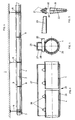
- a part of a ceiling 1 is shown, on which a sewage pipe 2, preferably made of plastic, is suspended or supported.
- the waste water line 2 consists of individual line parts which are welded together watertight by means of electric sleeves 3.
- the waste water pipe 2 is supported on a support 4, which support can have any cross-section, be it round, square or other shape. It serves to hold the sewage pipe 2 and protects it this before deflection.
- the waste water pipe 2 is held in a pipe clamp 6 and optionally provided with insulation 9.
- Guide supports 8 are arranged between the pipe clamps 6, so that the free span between two pipe clamps 6 with a pipe length of 6 m between two successive electric sleeves 3, as shown in FIG. 1, is, for example, 3 m and between a guide support 8 and the following Pipe clamp 6 1.50 m.
- the pipe clamp 6 shown in FIG. 2 has an upper part 11 with a threaded pin 12, a cover plate 13 and a threaded sleeve 14.
- the ceiling tile is provided with slots so that it can be installed correctly on the ceiling.
- the lower part 17 of the pipe clamp 6 is additionally provided with a guide element 18, here U-shaped, the two legs of which each have an opening 19. These serve to receive a wedge 20.
- This wedge 20 is shown in FIG. 5. It is conical both in height and in width. Therefore, its roof-shaped cross-sections are geometrically similar. Its lateral bearing surfaces 21 result in the locking effect with two lower edges 31 and 32 which converge. The conicity ensures self-locking.
- the wedge can be produced cheaply by means of a stamping and a bend.
- a locking surface preferably roughened, for locking the wedge, for example with a toothing which prevents the wedge from loosening automatically, for example due to vibrations.
- FIGS. 3 and 4 A further possibility of forming such a connecting device is shown in FIGS. 3 and 4, according to which two support tubes 4 pass through each other a connecting sleeve 25 are connected.
- the lower part of the connecting sleeve 25 is designed as a clamp 26, adapted to the corresponding dimensions of the support tubes 4, which here have a round cross section.
- the clamp 26 is provided with an overlying bracket 27 with four pairs of openings 28 for receiving four wedges 20.
- This sleeve-shaped connecting device is used to connect two pipes.
- the guide supports 8 are designed analogously to the pipe clamps 6. However, they are supported only on the carrier 4 without being suspended from the ceiling 1.
- the installation of the sewage pipe 2 is extremely simple, since moving pipe clamps and supports on the carrier is easy to do and the fixation by means of wedges 20 is effortlessly and securely a firm, yet detachable connection. In this way it is among other things it is possible to rigidly install plastic sewage pipes without any harmful deformation possibilities.
Landscapes
- Engineering & Computer Science (AREA)
- General Engineering & Computer Science (AREA)
- Mechanical Engineering (AREA)
- Supports For Pipes And Cables (AREA)
- Coupling Device And Connection With Printed Circuit (AREA)
- Monitoring And Testing Of Exchanges (AREA)
- Manufacturing Of Electric Cables (AREA)
- Pipe Accessories (AREA)
- Sewage (AREA)
Priority Applications (1)
| Application Number | Priority Date | Filing Date | Title |
|---|---|---|---|
| AT87119421T ATE61085T1 (de) | 1987-01-15 | 1987-12-31 | Anlage mit einer freiliegend aufgehaengten rohrleitung. |
Applications Claiming Priority (2)
| Application Number | Priority Date | Filing Date | Title |
|---|---|---|---|
| CH124/87 | 1987-01-15 | ||
| CH12487 | 1987-01-15 |
Publications (2)
| Publication Number | Publication Date |
|---|---|
| EP0274760A1 EP0274760A1 (de) | 1988-07-20 |
| EP0274760B1 true EP0274760B1 (de) | 1991-02-27 |
Family
ID=4179803
Family Applications (1)
| Application Number | Title | Priority Date | Filing Date |
|---|---|---|---|
| EP87119421A Expired - Lifetime EP0274760B1 (de) | 1987-01-15 | 1987-12-31 | Anlage mit einer freiliegend aufgehängten Rohrleitung |
Country Status (4)
| Country | Link |
|---|---|
| EP (1) | EP0274760B1 (da) |
| AT (1) | ATE61085T1 (da) |
| DE (1) | DE3768242D1 (da) |
| DK (1) | DK170183B1 (da) |
Cited By (1)
| Publication number | Priority date | Publication date | Assignee | Title |
|---|---|---|---|---|
| EP1043531A2 (de) | 1999-04-06 | 2000-10-11 | Geberit Technik Ag | Haltevorrichtung für eine wasserführende Rohrleitung |
Families Citing this family (2)
| Publication number | Priority date | Publication date | Assignee | Title |
|---|---|---|---|---|
| NL1020580C2 (nl) | 2002-05-13 | 2003-11-14 | Walraven J Van Bv | Beugel. |
| DE50208797D1 (de) | 2002-10-16 | 2007-01-04 | Geberit Technik Ag | Rohrschelle |
Citations (2)
| Publication number | Priority date | Publication date | Assignee | Title |
|---|---|---|---|---|
| EP0160890A2 (de) * | 1984-04-26 | 1985-11-13 | Toschi Produktions-GmbH | Auf einem Stützgerüst befestigbarer Abgaskanal |
| EP0165370A1 (fr) * | 1984-05-14 | 1985-12-27 | Jan Vrijhof | Dispositif de suspension |
Family Cites Families (7)
| Publication number | Priority date | Publication date | Assignee | Title |
|---|---|---|---|---|
| DE7126824U (da) * | 1900-01-01 | Badische Eisen-U. Blechwarenfabrik Gmbh | ||
| US2889145A (en) * | 1955-03-07 | 1959-06-02 | Charles G Hoffman | Apparatus for supporting hot air ducts and the like |
| US3506227A (en) * | 1967-11-06 | 1970-04-14 | Trw Inc | Hanger for elongate members |
| FR2220648A1 (da) * | 1973-03-07 | 1974-10-04 | Zaidan Joseph | |
| SE403176B (sv) * | 1976-12-22 | 1978-07-31 | Svenska Kram Ab | Lostagbar fattning kring ror eller solid profil med rektangulert tversnitt |
| FR2409411A1 (fr) * | 1977-11-22 | 1979-06-15 | Entrepose | Raccord perfectionne de jonction pour tubes et barres |
| FR2549543A1 (fr) * | 1983-07-18 | 1985-01-25 | Bertoni Daniel | Clavette a deux faces non paralleles munie d'un moyen de verrouillage |
-
1987
- 1987-12-31 AT AT87119421T patent/ATE61085T1/de not_active IP Right Cessation
- 1987-12-31 DE DE8787119421T patent/DE3768242D1/de not_active Expired - Lifetime
- 1987-12-31 EP EP87119421A patent/EP0274760B1/de not_active Expired - Lifetime
-
1988
- 1988-01-06 DK DK002988A patent/DK170183B1/da not_active Application Discontinuation
Patent Citations (2)
| Publication number | Priority date | Publication date | Assignee | Title |
|---|---|---|---|---|
| EP0160890A2 (de) * | 1984-04-26 | 1985-11-13 | Toschi Produktions-GmbH | Auf einem Stützgerüst befestigbarer Abgaskanal |
| EP0165370A1 (fr) * | 1984-05-14 | 1985-12-27 | Jan Vrijhof | Dispositif de suspension |
Cited By (1)
| Publication number | Priority date | Publication date | Assignee | Title |
|---|---|---|---|---|
| EP1043531A2 (de) | 1999-04-06 | 2000-10-11 | Geberit Technik Ag | Haltevorrichtung für eine wasserführende Rohrleitung |
Also Published As
| Publication number | Publication date |
|---|---|
| DK2988A (da) | 1988-07-16 |
| EP0274760A1 (de) | 1988-07-20 |
| DK2988D0 (da) | 1988-01-06 |
| DK170183B1 (da) | 1995-06-06 |
| DE3768242D1 (de) | 1991-04-04 |
| ATE61085T1 (de) | 1991-03-15 |
Similar Documents
| Publication | Publication Date | Title |
|---|---|---|
| DE69819838T2 (de) | Vorrichtung zum Zusammenbau zweier Rohre | |
| DE3921719A1 (de) | Deckenverkleidung | |
| DE8912630U1 (de) | Trägerklammer zur Halterung von Bauteilen, z.B. für Rohre u.dgl. | |
| DE3936198C2 (da) | ||
| EP0274760B1 (de) | Anlage mit einer freiliegend aufgehängten Rohrleitung | |
| DE2743819C3 (de) | Deckenstrahlungsheizung für Hallen u.a. Bauten | |
| DE1907473B2 (de) | Vorrichtung zur Halterung von Install ationsrohrleitungen | |
| DE19707592C2 (de) | Deckendurchführung für eine Abgasleitung einer Heizungsanlage | |
| WO1993016246A1 (de) | Vorrichtung zur schalldämmung in räumen | |
| DE19506661C2 (de) | Hänger für Rohrleitungen | |
| DE4130011A1 (de) | Befestigungselement | |
| EP3757305B1 (de) | Arbeitsraum | |
| DE2519641A1 (de) | Halter zum festhalten von installationsteilen | |
| DE2902759C2 (de) | Vorrichtung zur Befestigung von Rohrprofilen an tragenden Flächen | |
| DE9414600U1 (de) | Anordnung zur schwingungsdämpfenden Befestigung eines Leitungsrohrs an einer tragenden Wand | |
| DE10161720C1 (de) | Vorrichtung zum Befestigen hängender Rohrleitungen | |
| DE9013433U1 (de) | Vorrichtung zur Fixierung des Abstandes von an einem Träger festzulegenden Rohrleitungen | |
| DE2830639B2 (de) | Einrichtung zur Installation von Kabeln, Rohren u.dgl | |
| DE102005000174A1 (de) | Träger für Installationen im Bereich der Haustechnik und der Industrie | |
| EP1079168A1 (de) | Vorrichtung zur Anbringung und axialen Festlegung einer Rohrleitung | |
| DE2339417C3 (de) | Aufhängekette für Phasenseile an einem Leitungsmast | |
| DE2110184A1 (de) | Rohrhalterung | |
| AT332066B (de) | Anordnung bei herabhangender decke | |
| DD220995A1 (de) | Rohrbefestigung | |
| CH672360A5 (da) |
Legal Events
| Date | Code | Title | Description |
|---|---|---|---|
| PUAI | Public reference made under article 153(3) epc to a published international application that has entered the european phase |
Free format text: ORIGINAL CODE: 0009012 |
|
| AK | Designated contracting states |
Kind code of ref document: A1 Designated state(s): AT BE CH DE IT LI NL |
|
| 17P | Request for examination filed |
Effective date: 19890111 |
|
| 17Q | First examination report despatched |
Effective date: 19890612 |
|
| ITF | It: translation for a ep patent filed | ||
| GRAA | (expected) grant |
Free format text: ORIGINAL CODE: 0009210 |
|
| AK | Designated contracting states |
Kind code of ref document: B1 Designated state(s): AT BE CH DE IT LI NL |
|
| REF | Corresponds to: |
Ref document number: 61085 Country of ref document: AT Date of ref document: 19910315 Kind code of ref document: T |
|
| REF | Corresponds to: |
Ref document number: 3768242 Country of ref document: DE Date of ref document: 19910404 |
|
| PLBE | No opposition filed within time limit |
Free format text: ORIGINAL CODE: 0009261 |
|
| STAA | Information on the status of an ep patent application or granted ep patent |
Free format text: STATUS: NO OPPOSITION FILED WITHIN TIME LIMIT |
|
| 26N | No opposition filed | ||
| PGFP | Annual fee paid to national office [announced via postgrant information from national office to epo] |
Ref country code: BE Payment date: 20010315 Year of fee payment: 14 |
|
| PG25 | Lapsed in a contracting state [announced via postgrant information from national office to epo] |
Ref country code: BE Free format text: LAPSE BECAUSE OF NON-PAYMENT OF DUE FEES Effective date: 20011231 |
|
| BERE | Be: lapsed |
Owner name: GEBERIT A.G. ARMATUREN & APPARATEFABRIK Effective date: 20011231 |
|
| PGFP | Annual fee paid to national office [announced via postgrant information from national office to epo] |
Ref country code: NL Payment date: 20051204 Year of fee payment: 19 |
|
| PGFP | Annual fee paid to national office [announced via postgrant information from national office to epo] |
Ref country code: AT Payment date: 20051213 Year of fee payment: 19 |
|
| PG25 | Lapsed in a contracting state [announced via postgrant information from national office to epo] |
Ref country code: IT Free format text: LAPSE BECAUSE OF NON-PAYMENT OF DUE FEES;WARNING: LAPSES OF ITALIAN PATENTS WITH EFFECTIVE DATE BEFORE 2007 MAY HAVE OCCURRED AT ANY TIME BEFORE 2007. THE CORRECT EFFECTIVE DATE MAY BE DIFFERENT FROM THE ONE RECORDED. Effective date: 20051231 |
|
| PGFP | Annual fee paid to national office [announced via postgrant information from national office to epo] |
Ref country code: DE Payment date: 20060103 Year of fee payment: 19 |
|
| PGFP | Annual fee paid to national office [announced via postgrant information from national office to epo] |
Ref country code: CH Payment date: 20060227 Year of fee payment: 19 |
|
| PG25 | Lapsed in a contracting state [announced via postgrant information from national office to epo] |
Ref country code: LI Free format text: LAPSE BECAUSE OF NON-PAYMENT OF DUE FEES Effective date: 20061231 Ref country code: CH Free format text: LAPSE BECAUSE OF NON-PAYMENT OF DUE FEES Effective date: 20061231 |
|
| PG25 | Lapsed in a contracting state [announced via postgrant information from national office to epo] |
Ref country code: NL Free format text: LAPSE BECAUSE OF NON-PAYMENT OF DUE FEES Effective date: 20070701 |
|
| PG25 | Lapsed in a contracting state [announced via postgrant information from national office to epo] |
Ref country code: DE Free format text: LAPSE BECAUSE OF NON-PAYMENT OF DUE FEES Effective date: 20070703 |
|
| REG | Reference to a national code |
Ref country code: CH Ref legal event code: PL |
|
| NLV4 | Nl: lapsed or anulled due to non-payment of the annual fee |
Effective date: 20070701 |
|
| PG25 | Lapsed in a contracting state [announced via postgrant information from national office to epo] |
Ref country code: AT Free format text: LAPSE BECAUSE OF NON-PAYMENT OF DUE FEES Effective date: 20061231 |