EP0274973A1 - Dispositifs autonomes pour chauffer des récipients alimentaires - Google Patents
Dispositifs autonomes pour chauffer des récipients alimentaires Download PDFInfo
- Publication number
- EP0274973A1 EP0274973A1 EP87430036A EP87430036A EP0274973A1 EP 0274973 A1 EP0274973 A1 EP 0274973A1 EP 87430036 A EP87430036 A EP 87430036A EP 87430036 A EP87430036 A EP 87430036A EP 0274973 A1 EP0274973 A1 EP 0274973A1
- Authority
- EP
- European Patent Office
- Prior art keywords
- knives
- axis
- tank
- container
- grids
- Prior art date
- Legal status (The legal status is an assumption and is not a legal conclusion. Google has not performed a legal analysis and makes no representation as to the accuracy of the status listed.)
- Granted
Links
- 235000013305 food Nutrition 0.000 title claims abstract description 17
- 238000010438 heat treatment Methods 0.000 title claims description 16
- 239000003153 chemical reaction reagent Substances 0.000 claims abstract description 10
- 238000005192 partition Methods 0.000 claims abstract description 4
- ODINCKMPIJJUCX-UHFFFAOYSA-N Calcium oxide Chemical compound [Ca]=O ODINCKMPIJJUCX-UHFFFAOYSA-N 0.000 claims description 30
- XLYOFNOQVPJJNP-UHFFFAOYSA-N water Substances O XLYOFNOQVPJJNP-UHFFFAOYSA-N 0.000 claims description 21
- 235000012255 calcium oxide Nutrition 0.000 claims description 15
- 239000000292 calcium oxide Substances 0.000 claims description 15
- 239000004033 plastic Substances 0.000 claims description 11
- 229920003023 plastic Polymers 0.000 claims description 11
- 235000008733 Citrus aurantifolia Nutrition 0.000 claims description 7
- 235000011941 Tilia x europaea Nutrition 0.000 claims description 7
- 239000004571 lime Substances 0.000 claims description 7
- 239000012528 membrane Substances 0.000 claims description 6
- 239000011248 coating agent Substances 0.000 claims description 2
- 238000000576 coating method Methods 0.000 claims description 2
- 239000011810 insulating material Substances 0.000 claims 1
- 238000004519 manufacturing process Methods 0.000 description 2
- -1 polyethylene Polymers 0.000 description 2
- 239000004698 Polyethylene Substances 0.000 description 1
- 239000004743 Polypropylene Substances 0.000 description 1
- 229920005830 Polyurethane Foam Polymers 0.000 description 1
- ATJFFYVFTNAWJD-UHFFFAOYSA-N Tin Chemical compound [Sn] ATJFFYVFTNAWJD-UHFFFAOYSA-N 0.000 description 1
- XAGFODPZIPBFFR-UHFFFAOYSA-N aluminium Chemical compound [Al] XAGFODPZIPBFFR-UHFFFAOYSA-N 0.000 description 1
- 229910052782 aluminium Inorganic materials 0.000 description 1
- 230000001413 cellular effect Effects 0.000 description 1
- 238000010276 construction Methods 0.000 description 1
- 238000005520 cutting process Methods 0.000 description 1
- 238000009826 distribution Methods 0.000 description 1
- 239000004794 expanded polystyrene Substances 0.000 description 1
- 239000011888 foil Substances 0.000 description 1
- 235000021268 hot food Nutrition 0.000 description 1
- 239000000463 material Substances 0.000 description 1
- 235000012054 meals Nutrition 0.000 description 1
- 239000000203 mixture Substances 0.000 description 1
- 229920000728 polyester Polymers 0.000 description 1
- 229920000573 polyethylene Polymers 0.000 description 1
- 229920001155 polypropylene Polymers 0.000 description 1
- 239000011496 polyurethane foam Substances 0.000 description 1
- 229920000915 polyvinyl chloride Polymers 0.000 description 1
- 239000004800 polyvinyl chloride Substances 0.000 description 1
- 235000013324 preserved food Nutrition 0.000 description 1
- 230000000750 progressive effect Effects 0.000 description 1
- 230000001681 protective effect Effects 0.000 description 1
- 230000005855 radiation Effects 0.000 description 1
- 235000015504 ready meals Nutrition 0.000 description 1
- 238000003860 storage Methods 0.000 description 1
- 239000002470 thermal conductor Substances 0.000 description 1
Images


Classifications
-
- B—PERFORMING OPERATIONS; TRANSPORTING
- B65—CONVEYING; PACKING; STORING; HANDLING THIN OR FILAMENTARY MATERIAL
- B65D—CONTAINERS FOR STORAGE OR TRANSPORT OF ARTICLES OR MATERIALS, e.g. BAGS, BARRELS, BOTTLES, BOXES, CANS, CARTONS, CRATES, DRUMS, JARS, TANKS, HOPPERS, FORWARDING CONTAINERS; ACCESSORIES, CLOSURES, OR FITTINGS THEREFOR; PACKAGING ELEMENTS; PACKAGES
- B65D81/00—Containers, packaging elements, or packages, for contents presenting particular transport or storage problems, or adapted to be used for non-packaging purposes after removal of contents
- B65D81/34—Containers, packaging elements, or packages, for contents presenting particular transport or storage problems, or adapted to be used for non-packaging purposes after removal of contents for packaging foodstuffs or other articles intended to be cooked or heated within the package
- B65D81/3484—Packages having self-contained heating means, e.g. heating generated by the reaction of two chemicals
-
- A—HUMAN NECESSITIES
- A47—FURNITURE; DOMESTIC ARTICLES OR APPLIANCES; COFFEE MILLS; SPICE MILLS; SUCTION CLEANERS IN GENERAL
- A47J—KITCHEN EQUIPMENT; COFFEE MILLS; SPICE MILLS; APPARATUS FOR MAKING BEVERAGES
- A47J36/00—Parts, details or accessories of cooking-vessels
- A47J36/24—Warming devices
- A47J36/28—Warming devices generating the heat by exothermic reactions, e.g. heat released by the contact of unslaked lime with water
Definitions
- the present invention relates to autonomous devices for heating food containers.
- the technical sector of the invention is that of the manufacture of ready meals and other canned food.
- Disposable devices are already known after use intended to rapidly heat receptacles of the sterilized tray or can type containing a cooked dish, without having to use traditional heating means such as gas or electric stoves.
- the disposable container can also receive a food container such as a tray or a can.
- the two reagents are brought into contact and the content of the food container is heated rapidly by the heat due to the exothermic reaction.
- the two reagents are advantageously quicklime and water which are very inexpensive reagents, the mixture of which gives off sufficient heat without giving rise to any harmful product.
- FR patent application. 81 / 20.904 and the FR Addition Certificate. 82 / 17.033 describe devices of this known type comprising a disposable protective container after use, which contains in its bottom a heating tray, which contains a plastic bag which is filled with water and surrounded by quicklime and which is provided with a tear cord that we fire when we want to cause the exothermic reaction.
- U.S. Patent 3,871,357 describes devices of the same type comprising a pocket filled with water and a tongue provided with a sharp blade which makes it possible to describe the water pocket.
- the devices according to the invention are devices which comprise, in known manner, a disposable container after use comprising an upper compartment which contains a food container which it is desired to heat and a lower compartment which contains reagents which give rise to a exothermic reaction when brought into contact, preferably powdered quicklime and water, these two reagents being separated from one another by one or more thin and tight walls and the device comprises means for tear the walls when you want to heat the food container.
- the means for tearing the watertight walls comprise at least one axis which carries radial knives and which is provided with a visible operating head outside the tank and they further comprise at least one grid which protects said knives and which comprises openings transverse to said axis.
- the lower compartment contains a first plastic bag filled with quicklime which is placed in the bottom of said tank and it contains a second plastic bag filled with water which is placed above the bag. quicklime and said grids and said axis carrying the knives are interposed between the two pockets.
- the knives are arranged in transverse planes located between the openings of said grids, so that said knives abut against said grids if one turns said operating head and said axis can slide longitudinally to bring said said knives in front of said transverse openings of said grids.
- the operating head is connected to the tank by a safety member that a shear pin or a tearable seal.
- the axis carries knives which are angularly offset, so that it is possible to adjust the heating rate.
- the invention results in new autonomous devices making it possible to reheat cooked meals when consuming them.
- the disposable devices according to the invention which include quicklime and water enclosed in plastic bags, are inexpensive to manufacture because the reagents are very economical and the sealed bagging thereof is a easy operation to perform economically in large series.
- the waterproof pockets prevent quicklime from absorbing moisture or water from coming into contact with lime during storage and transport.
- the devices according to the invention comprising an axis provided with knives make it possible to obtain a progressive release of calories and to regulate the heating speed by acting on the degree of rotation of the control button as on the control buttons of a burner with gas or an electric hot plate.
- the devices according to the invention comprising an axis carrying knives angularly offset allow better adjustment of the heating rate.
- the grid or grids which surround the axis carrying the knives confer good security because they prevent the knives from accidentally cutting through the watertight walls.
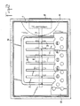
- FIGS 1, 2 and 3 show a preferred embodiment of a device according to the invention.
- This device comprises a tray 1 which is disposable after use.
- the tank 1 is advantageously constructed of plastic, for example polyethylene or polypropylene, polyester or polyvinyl chloride.
- the tray 1 is intended to receive in its upper part a food container 2, which is for example a rectangular tray of aluminum foil or a sealed tin can, containing a food product, for example a prepared sterilized dish.
- the tray 1 follows the shape of the container 2 which it must contain and which can have various shapes.
- the object of the device according to the invention is to allow the food contained in the container 2 to be heated just before it is consumed.
- the device according to the invention is designed to keep food warm while it is consumed.
- the tank 1 contains a first plastic bag 3, which is filled with quicklime and which is hermetically sealed.
- the bag 3 is placed in the bottom of the tank 1. It contains an amount of quicklime which can vary for example between 100 g and 250 g, depending on the size of the container 2.
- the tank 1 contains a second waterproof plastic bag 4 which contains water, the weight of water being for example of the order of 1.5 times the weight of quicklime.
- the tank 1 has a horizontal axis 5 which is arranged between two grids 6 and 7, which are placed between the two pockets 3 and 4.
- the axis 5 carries at one of its ends an operating head 8, for example a button or a handle which is visible outside of the tank and which makes it possible to operate the axis 5 in rotation and possibly in axial translation .
- an operating head 8 for example a button or a handle which is visible outside of the tank and which makes it possible to operate the axis 5 in rotation and possibly in axial translation .
- FIG. 1 represents an embodiment in which the tank 1 comprises a recessed housing inside which the button 8 is housed, so that it is protected by the tray.
- the shaft 5 carries knives 9 which are constituted for example by pointed pins implanted radially on the shaft 5 and diametrically opposite.
- the grids 6 and 7 are advantageously two curved plastic plates along their longitudinal edges which are applied one against the other, as can be seen in FIG. 3, so that the two plates delimit a cage for the interior of which the shaft 5 and the knives 9 are contained at rest.
- the grids 6 and 7 have transverse openings 10 which are elongated in the direction perpendicular to the axis 5.
- the number of openings 10 is equal to or greater than the number of knives 9.
- Figures 1 to 3 show a preferred embodiment, in which the shaft 5 is mounted in bearings 11, in which it can rotate and also move axially.
- Figures 1 to 3 show the device at rest, that is to say outside the heating period.
- the knives 9 are then located in the horizontal plane of the shaft 5 and they are offset longitudinally relative to the openings 10, so that if the knob 8 is turned without having moved it axially, the knives 9 abut against the grids, which constitutes a first safety measure which prevents the pockets 3 and 4 from being cut accidentally by the knives during handling.
- the button 8 is connected to the tank 1 by a shearable pin 12 and it is necessary to force on the button 8 to shear the pin 12 before being able to operate the button, which constitutes a second security.
- one security can be used. We can remove the shear pin 12 or we can provide an axis 5 not movable in translation and, in this case, the knives 9 are placed opposite the openings 10 and the pin 12 prohibits rotation of the shaft as long as it n has not been sheared.
- a device further comprises an openwork partition 13, for example a perforated plate or a grid, which is placed above the water bag 4 and which divides the tank 1 in two compartments, a lower compartment which contains the pockets 3 and 4 containing the heating reagents and the tear mechanism of the pockets and an upper compartment which contains the food container 2 which must be heated.
- an openwork partition 13 for example a perforated plate or a grid, which is placed above the water bag 4 and which divides the tank 1 in two compartments, a lower compartment which contains the pockets 3 and 4 containing the heating reagents and the tear mechanism of the pockets and an upper compartment which contains the food container 2 which must be heated.
- the device which has just been described is placed inside a thermal insulating container 14 equipped with a cover 15.
- Figures 1 to 3 show an embodiment in which the container 14 and the cover 15 are made of a good thermal insulating cellular material and inexpensive, for example made of expanded polystyrene or polyurethane foam.
- the internal walls of the container 14 and of the cover 15 carry a reflective coating 16, for example a sheet of aluminized plastic which reflects the thermal radiation emitted by the tank 1.
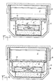
- FIGS. 3 and 4 are cross section of an alternative embodiment. The homologous parts are represented by the same references in FIGS. 3 and 4.
- the powdery quicklime 3 is placed in the bottom of the tank 1.
- the tank has a shoulder 17, on which is glued or heat-sealed, a membrane 18 which isolates the lower compartment containing the lime. There are above the membrane 18 the two grids 6 and 7 which delimit a cage in which the shaft 5 carrying the knives rotates.
- FIG. 4 shows a shaft 5 carrying knives 19 and 20 which are angularly offset. This arrangement makes it possible to obtain different heating rates. If the operating knob 8 is turned an eighth of a turn, clockwise, only the knives 19 cut the waterproof membrane 18 and the water pocket 4, so that the number of nicks is reduced and the exothermic reaction is slower.
- the shaft represented in FIG. 4 carrying knives angularly offset can be used on a device according to FIG. 3 and conversely a shaft according to FIG. 3 can be used with a device according to FIG. 4.
- the knife mechanism mounted on an axis carrying an operating button which must be pushed axially and then turned more or less to adjust the heating rate reproduces the type of button control existing on gas or electric burners, this which facilitates the use of the devices according to the invention.
- An important advantage of the devices according to the invention lies in the fact that the knives mounted on an axis make, in the lower membrane 18 or in the pocket containing the lime and in the water pocket, slots which are diametrically opposite with respect to axis 5, as long as the operating button 8 has made less than a quarter of a turn.
- the water flowing from the water bag very gradually comes into contact with the lime and that the heating speed can be adjusted by turning the operating knob more or less. This avoids producing a too rapid exothermic reaction which leads to a high loss of calories and a poor temperature distribution in the food contained in the container 2, if these are poor thermal conductors, which is often the case.
- organoleptic qualities of food are often linked to the speed of heating and the devices according to the invention make it possible to obtain a gradual rise in temperature which preserves the taste and the quality of cooked dishes.
- the above description relates to devices comprising a single axis 5 provided with knives. It is specified that the invention extends to the case of devices which would comprise several axes provided with knives, which would make it possible to obtain even more possibilities for adjusting the heating speed.
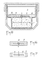
- FIGS. 1 to 5 shows an axial section of another embodiment.
- the homologous parts are represented by the same references in FIGS. 1 to 5.
- the device comprises a single grid 21, which is interposed between the two pockets 3 and 4 and which comprises transverse openings 22.
- the shaft 5 carrying radial knives 6 is placed in longitudinal notches 23 which form bearings.
- the knives 6 are located in the transverse planes of the openings 22.
- Figure 6 is a cross section along VI-VI of the axis and the grid passing through a bearing.
- FIG. 7 is a cross section along VII-VII passing through the axis of an opening 22.
- the knives 6 are placed in the thickness of the grid which protects them and prevents them from tearing the pockets.
- the knob 8 is turned, the knives 6 pivot in the openings 22 and they protrude outside the upper and lower walls of the grid, tearing the pockets 3 and 4.
- FIGS. 3, 4 and 8 show a cross section of another embodiment.
- the homologous parts are represented by the same references in FIGS. 3, 4 and 8.
- the device comprises a grid 24 which is arranged under the tray to be heated 2 and above the water bag 4 which is popsed on the quicklime bag 3, placed in the bottom of the tank 1.
- the grid 24 has perforations 25 for the passage of steam.
- the shaft 5 carries radial knives 6 extending on one side. At rest, these knives are housed in openings 26 of the grid 24 which extend on the same side as the knives.
- the knives 6 have a sufficient length to reach and tear the top of the lime ladle 3 when the button 8 is operated. The knives are shown in dotted lines in this position.
- Figures 1 and 5 show a button 8 which is connected to the tray 1 by a shear pin 12. It is specified that this pin can be replaced by other equivalent safety members for example by a tear-off or tear-off seal.
Landscapes
- Engineering & Computer Science (AREA)
- Food Science & Technology (AREA)
- Life Sciences & Earth Sciences (AREA)
- Mechanical Engineering (AREA)
- Chemical & Material Sciences (AREA)
- Chemical Kinetics & Catalysis (AREA)
- Cookers (AREA)
- Devices For Warming Or Keeping Food Or Tableware Hot (AREA)
- General Preparation And Processing Of Foods (AREA)
- Vending Machines For Individual Products (AREA)
Abstract
Description
- La présente invention a pour objet des dispositifs autonomes pour chauffer des récipients alimentaires.
- Le secteur technique de l'invention est celui de la fabrication des plats cuisinés et autres conserves alimentaires.
- On connaît déjà des dispositifs jetables après usage destinés à chauffer rapidement des récipients du type barquette ou boîte de conserve stérilisée contenant un plat cuisiné, sand avoir à utiliser des moyens de chauffage traditionnels tels que des réchauds à gaz ou électriques.
- Ces dispositifs connus comportent un bac jetable après usage, dans le fond duquel on place deux réactifs qui donnent naissance à une réaction exothermique lorsqu'on les met en contact l'un de l'autre.
- Le bac jetable peut recevoir, en outre, un récipient alimentaire du type barquette ou boîte de conserve.
- Avant de consommer les aliments contenus dans le récipient, on provoque la mise en contact des deux réactifs et le contenu du récipient alimentaire est chauffé rapidement par la chaleur due à la réaction exothermique.
- Les deux réactifs sont avantageusement de la chaux vive et de l'eau qui sont des réactifs très peu onéreux, dont le mélange dégage suffisamment de chaleur sans donner naissance à aucun produit nocif.
- Ces dispositifs connus sont destinés à mettre à la disposition de tous ceux qui doivent s'alimenter dans des conditions qui ne permettent pas de faire du feu, des moyens leur permettant de manger des aliments chauds. Ils sont destinés, notamment aux soldats en campagne ou en manoeuvres, aux campeurs, aux alpinistes, aux routiers et éventuellement à ceux qui doivent s'alimenter sur des chantiers ou hors de chez eux.
- La demande de brevet FR. 81/20.904 et le Certificat d'Addition FR. 82/17.033 (S. BENMUSSA) décrivent des dispositifs de ce type connu comportant un conteneur de protection jetable après usage, qui contient dans son fond une barquette de chauffe, qui contient une poche en matière plastique qui est remplie d'eau et entourée de chaux vive et qui est munie d'un cordon de déchirure que l'on tire au moment où l'on veut provoquer la réaction exothermique.
- La publication FR. A. 2.348.121 décrit un dispositif du même type.
- Le brevet U.S.A. 3.871.357 décrit des dispositifs du même type comportant une poche remplie d'eau et une languette munie d'un lame tranchante qui permet de décrirer la poche à eau.
- Les dispositifs selon l'invention sont des dispositifs qui comportent, de façon connue, un bac jetable après usage comportant un compartiment supérieur qui contient un récipient alimentaire que l'on désire chauffer et un compartiment inférieur qui contient d eux réactifs qui donnent naissance à une réaction exothermique lorsqu'ils sont mis en contact, de préférence de la chaux vive pulvérulente et de l'eau, ces deux réactifs étant séparés l'un de l'autre par une ou plusieurs parois minces et étanches et le dispositif comporte des moyens pour déchirer les parois au moment où l'on désire chauffer le récipient alimentaire.
- Les objectifs de l'invention sont atteints au moyen d'un dispositif dans lequel les moyens pour déchirer les parois étanches comportent au moins un axe qui porte des couteaux radiaux et qui est muni d'une tête de manoeuvre apparente à l'extérieur du bac et ils comportent, en outre, au moins une grille qui protège lesdits couteaux et qui comporte des ouvertures transversales audit axe.
- Selon un mode de réalisation préférentiel, le compartiment inférieur contient une première poche enmatière plastique remplie de chaux vive qui est posée dans le fond dudit bac et il contient une deuxième poche en matière plastique remplie d'eau qui est placée au-dessus de la poche de chaux vive et lesdites grilles ainsi que ledit axe portant les couteaux sont intercalés entre les deux poches.
- Selon un mode de réalisation préférentiel, les couteaux sont disposés dans des plans transversaux situés entre les ouvertures desdites grilles, de sorte que lesdits couteaux viennent buter contre lesdites grilles si l'on tourne ladite tête de manoeuvre et ledit axe peut coulisser longitudinalement pour amener lesdits couteaux en face desdites ouvertures transversales desdites grilles.
- Avantageusement, la tête de manoeuvre est reliée au bac par un organe de sécurité qu'une goupille cisaillable ou un sceau déchirable. Selon un mode de réalisation préférentiel, l'axe porte des couteaux qui sont décalés angulairement, de sorte qu'il est possible de régler l'allure de chauffage.
- L'invention a pour résultat de nouveaux dispositifs autonomes permettant de réchauffer des plats cuisinés au moment de les consommer.
- Les dispositifs jetables selon l'invention, qui comportent de la chaux vive et de l'eau enfermées dans des poches en matière plastiques, sont peu onéreux à fabriquer car les réactifs sont très économiques et la mise en sac étanche de ceux-ci est une opération facile à réaliser économiquement en grande série.
- De plus, les poches étanches évitent que la chaux vive n'absorbe de l'humidité ou que l'eau ne risque de venir au contact de la chaux pendant le stockage et le transport.
- Les dispositifs selon l'invention comportant un axe muni de couteaux permettent d'obtenir un dégagement de calories progressif et de régler la vitesse de chauffe en agissant sur le degré de rotation du bouton de commande comme sur les boutons de commande d'un brûleur à gaz ou d'une plaque chauffante électrique.
- Les dispositifs selon l'invention comportant un axe portant des couteaux décalés angulairement permettent de mieux régler l'allure de chauffage.
- La ou les grilles qui entourent l'axe portant les couteaux confèrent une bonne sécurité du fait qu'elles empêchent les couteaux de découper accidentellement les parois étanches.
- Les modes de réalisation dans lesquels l'axe doit être décalé axialement avant de pouvoir le faire pivoter et dans lesquels l'axe est muni d'une goupille de sécurité cisaillable, accroissent encore la sécurité d'emploi.
- La description suivante se réfère aux dessins annexés qui représentent, sans aucun caractère limitatif, des exemples de réalisation de dispositifs selon l'invention.
- La figure 1 est une coupe longitudinale d'un dispositif selon l'invention.
- La figure 2 est une coupe selon II-II de la figure 1 avec arrachement partiel de la plaque perforée et sans la poche à eau.
- La figure 3 est une coupe transversale de la figure 1.
- La figure 4 est une coupe transversale d'une variante de réalisation.
- Les figures 5, 6 et 7 représentent une coupe longitudinale et des coupes axiales d'une variante de réalisation comportant une seule grille.
- La figure 8 représente une coupe transversale d'une autre variante de réalisation.
- Les figures 1, 2 et 3 représentent un mode de réalisation préférentiel d'un dispositif selon l'invention. Ce dispositif comporte un bac 1 qui est jetable après usage. Le bac 1 est construit avantageusement en matière plastique, par exemple en polyéthylène ou en polypropylène, en polyester ou en chlorure de polyvinyle. Le bac 1 est destiné à recevoir dans sa partie supérieure un récipient alimentaire 2, qui est par exemple une barquette rectangulaire en feuille d'aluminium ou une boîte de conserve étanche, contenant un produit alimentaire, par exemple un plat préparé stérilisé. Le bac 1 épouse la forme du récipient 2 qu'il doit contenir et qui peut présenter des formes variées.
- Le but du dispositif selon l'invention est de permettre de chauffer les aliments contenus dans le récipient 2, juste avant que ceux-ci soient consommés.
- Avantageusement, le dispositif selon l'invention est conçu pour maintenir les aliments au chaud pendant qu'ils sont consommés.
- Le bac 1 contient une première poche en matière plastique 3, qui est remplie de chaux vive et qui est scellée de façon hermétique. La poche 3 est posée dans le fond du bac 1. Elle contient une quantité de chaux vive qui peut varier par exemple entre 100 g et 250 g, selon la taille du récipient 2. Le bac 1 contient une deuxième poche étanche en matière plastique 4 qui contient de l'eau, le poids d'eau étant par exemple de l'ordre de 1,5 fois le poids de chaux vive.
- Le bac 1 comporte un axe horizontal 5 qui est disposé entre deux grilles 6 et 7, qui sont placées entre les deux poches 3 et 4.
- L'axe 5 porte à l'une de ses extrémités une tête de manoeuvre 8, par exemple un bouton ou une poignée qui est apparente à l'extérieur du bac et qui permet de manoeuvrer l'axe 5 en rotation et éventuellement en translation axiale.
- La figure 1 représente un mode de réalisation dans lequel le bac 1 comporte un logement en creux à l'intérieur duquel le bouton 8 est logé, de sorte qu'il est protégé par le bac.
- L'arbre 5 porte des couteaux 9 qui sont constitués par exemple par des broches pointues implantées radialement sur l'arbre 5 et diamétralement opposées.
- Les grilles 6 et 7 sont avantageusement deux plaques en matière plastique galbées le long de leurs bords longitudinaux qui sont appliqués l'un contre l'autre, comme on peut le voir sur la figure 3, de sorte que les deux plaques délimitent une cage à l'intérieur de laquelle l'arbre 5 et les couteaux 9 sont contenus au repos.
- Les grilles 6 et 7 comportent des ouvertures transversales 10 qui sont allongées dans le sens perpendiculaire à l'axe 5.
- Le nombre d'ouvertures 10 est égal ou supérieur au nombre de couteaux 9.
- Les figures 1 à 3 représentent un mode de réalisation préférentiel, dans lequel l'arbre 5 est monté dans des coussinets 11, dans lesquels il peut tourner et également se déplacer axialement.
- Les figures 1 à 3 représentent le dispositif au repos, c'est-à-dire en dehors de la période de chauffage. Les couteaux 9 sont alors situés dans le plan horizontal de l'arbre 5 et ils sont décalés longitudinalement par rapport aux ouvertures 10, de sorte que si l'on tourne le bouton 8 sans l'avoir déplacé axialement, les couteaux 9 butent contre les grilles, ce qui constitue une première sécurité qui évite que les poches 3 et 4 ne puissent être coupées accidentellement par les couteaux pendant les manutentions. De plus, le bouton 8 est relié au bac 1 par une goupille cisaillable 12 et il faut forcer sur le bouton 8 pour cisailler la goupille 12 avant de pouvoir manoeuvrer le bouton, ce qui constitue une deuxième sécurité.
- En variante, on peut utiliser une seule sécurité. On peut supprimer la goupille cisaillable 12 ou on peut prévoir un axe 5 non déplaçable en translation et, dans ce cas, les couteaux 9 sont placés en regard des ouvertures 10 et la goupille 12 interdit la rotation de l'arbre tant qu'elle n'a pas été cisaillée.
- Un dispositif selon l'invention comporte, en outre, une cloison ajourée 13, par exemple une plaque perforée ou une grille, qui est placée au-dessus de la poche à eau 4 et qui divise le bac 1 en deux compartiments, un compartiment inférieur qui contient les poches 3 et 4 contenant les réactifs de chauffage et le mécanisme de déchirure des poches et un compartiment supérieur qui contient le récipient alimentaire 2 qui doit être chauffé.
- Avantageusement, le dispositif qui vient d'être décrit est placé à l'intérieur d'un conteneur isolant thermique 14 équipé d'un couvercle 15.
- Les figures 1 à 3 représentent un mode de réalisation dans lequel le conteneur 14 et le couvercle 15 sont en un matériau cellulaire bon isolant thermique et peu onéreux,par exemple en polystyrène expansé ou en mousse de polyuréthane.
- Avantageusement, les parois internes du conteneur 14 et du couvercle 15 portent un revêtement réflecteur 16, par exemple une feuille de matière plastique aluminisée qui réfléchit les rayonnements thermiques émis par le bac 1.
- La figure 4 est une coupe transversale d'une variante de réalisation. Les parties homologues sont représentées par les mêmes repères sur les figures 3 et 4.
- Dans la variante selon la figure 3, la chaux vive pulvérulente 3 est placée dans le fond du bac 1.
- Le bac comporte un épaulement 17, sur lequel est collée ou thermosoudée de façon étanche, une membrane 18 qui isole le compartiment inférieur contenant la chaux. On retrouve au-dessus de la membrane 18 les deux grilles 6 et 7 qui délimitent une cage dans laquelle tourne l'arbre 5 portant les couteaux.
- Lorsqu'on fait tourner l'axe 5, les couteaux 9 coupent la membrane 18 et la poche à eau 4 et l'eau s'écoule progressivement vers la chaux.
- On a représenté sur la figure 4 un arbre 5 portant des couteaux 19 et 20 qui sont décalés angulairement. Cette disposition permet d'obtenir des allures de chauffe différentes. Si l'on tourne le bouton de manoeuvre 8 d'un huitième de tour, dans le sens des aiguilles d'une montre, seuls les couteaux 19 découpent la membrane étanche 18 et la poche à eau 4, de sorte que le nombre d'entailles est réduit et la réaction exothermique est plus lente.
- Si on tourne le bouton de manoeuvre 8 d'un quart de tour, les couteaux 20 agissent également et la réaction se produit plus rapidement.
- Bien entendu, l'arbre représenté sur la figure 4 portant des couteaux décalés angulairement peut être utilisé sur un dispositif selon la figure 3 et inversement un arbre selon la figure 3 peut être utilisé avec un dispositif selon la figure 4.
- On voit que le mécanisme à couteaux montés sur un axe portant un bouton de manoeuvre qui doit être poussé axialement puis tourné plus ou moins pour régler l'allure de chauffe reproduit le type de commande à boutons existant sur les brûleurs à gaz ou électriques,ce qui facilite l'utilisation des dispositifs selon l'invention.
- Un avantage important des dispositifs selon l'invention réside dans le fait que les couteaux montés sur un axe font,dans la membrane inférieure 18 ou dans la poche contenant la chaux et dans la poche à eau, des fentes qui sont diamétralement opposées par rapport à l'axe 5, tant que le bouton de manoeuvre 8 a fait moins d'un quart de tour. Il en résulte que l'eau qui s'écoule de la poche à eau arrive très progressivement au contact de la chaux et que l'on peut régler la vitesse de chauffage en tournant plus ou moins le bouton de manoeuvre. On évite ainsi de produire une réaction exothermique trop rapide qui conduit à uneperte élevée de calories et à une mauvaise répartition de température dans les aliments contenus dans le récipient 2, si ceux-ci sont mauvais conducteurs thermiques, ce qui est souvent le cas.
- De plus, on sait que les qualités organoleptiques des aliments sont souvent liées à la vitesse de chauffe et les dispositifs selon l'invention permettent d'obtenir une montée en température progressive qui préserve le goût et la qualité des plats cuisinés.
- La description qui précède concerne des dispositifs comportant un seul axe 5 muni de couteaux. Il est précisé que l'invention s'étend au cas de dispositifs qui comporteraient plusieurs axes munis de couteaux, ce qui permettrait d'obtenir encore plus de possibilités de réglage de la vitesse de chauffage.
- La figure 5 représente une coupe axiale d'une autre mode de réalisation. Les parties homologues sont représentées par les mêmes repères sur les figures 1 à 5.
- Dans cet exemple, le dispositif comporte une seule grille 21, qui est intercalée entre les deux poches 3 et 4 et qui comporte des ouvertures transversales 22. L'arbre 5 portant des couteaux radiaux 6 est placé dans des encoches longitudinales 23 qui forment des paliers. Les couteaux 6 sont situés dans les plans transversaux des ouvertures 22.
- La figure 6 est une coupe transversale selon VI-VI de l'axe et de la grille passant par un palier.
- La figure 7 est une coupe transversale selon VII-VII passant par l'axe d'une ouverture 22.
- Au repos, les couteaux 6 sont placés dans l'épaisseur de la grille qui les protège et évite que ceux-ci ne déchirent les poches. Lorsqu'on tourne le bouton 8, les couteaux 6 pivotent dans les ouvertures 22 et ils dépassent hors des parois supérieure et inférieure de la grille en déchirant les poches 3 et 4.
- La figure 8 représente une coupe transversale d'un autre mode de réalisation. Les parties homologues sont représentées par les mêmes repères sur les figures 3, 4 et 8.
- Dans cet exemple, le dispositif comporte une grille 24 qui est disposée sous la barquette à réchauffer 2 et au-dessus de la poche à eau 4 qui est popsée sur la poche de chaux vive 3, placée dans le fond du bac 1. La grille 24 comporte des perforations 25 pour le passage de la vapeur. L'arbre 5 porte des couteaux radiaux 6 s'étendant d'un seul côté. Au repos, ces couteaux sont logés dans des ouvertures 26 de la grille 24 qui s'étendent du même côté que les couteaux. Les couteaux 6 ont une longueur suffisante pour atteindre et déchirer le dessus de la poche à chaux 3 lorsque le bouton 8 est manoeuvré. Les couteaux sont représentés en pointillés dans cette position.
- Les figures 1 et 5 représentent un bouton 8 qui est relié au bac 1 par une goupille cisaillable 12. Il est précisé que cette goupille peut être remplacée par d'autres organes de sécurité équivalents par exemple par un sceau déchirable ou arrachable.
Claims (10)
Priority Applications (1)
| Application Number | Priority Date | Filing Date | Title |
|---|---|---|---|
| AT87430036T ATE52176T1 (de) | 1986-12-05 | 1987-12-04 | Selbstheizende vorrichtungen fuer nahrungsmittelbehaelter. |
Applications Claiming Priority (2)
| Application Number | Priority Date | Filing Date | Title |
|---|---|---|---|
| FR8617163 | 1986-12-05 | ||
| FR8617163A FR2607692B1 (fr) | 1986-12-05 | 1986-12-05 | Dispositifs autonomes pour chauffer des recipients alimentaires |
Publications (2)
| Publication Number | Publication Date |
|---|---|
| EP0274973A1 true EP0274973A1 (fr) | 1988-07-20 |
| EP0274973B1 EP0274973B1 (fr) | 1990-04-25 |
Family
ID=9341679
Family Applications (1)
| Application Number | Title | Priority Date | Filing Date |
|---|---|---|---|
| EP87430036A Expired - Lifetime EP0274973B1 (fr) | 1986-12-05 | 1987-12-04 | Dispositifs autonomes pour chauffer des récipients alimentaires |
Country Status (6)
| Country | Link |
|---|---|
| US (1) | US4809673A (fr) |
| EP (1) | EP0274973B1 (fr) |
| AT (1) | ATE52176T1 (fr) |
| DE (1) | DE3762386D1 (fr) |
| ES (1) | ES2014324B3 (fr) |
| FR (1) | FR2607692B1 (fr) |
Cited By (6)
| Publication number | Priority date | Publication date | Assignee | Title |
|---|---|---|---|---|
| US4513203A (en) * | 1981-05-30 | 1985-04-23 | International Business Machines Corporation | Mask and system for mutually aligning objects in ray exposure systems |
| EP0356093A1 (fr) * | 1988-08-12 | 1990-02-28 | Nissin Shokuhin Kabushiki Kaisha | Conteneur autochauffant |
| CN107660862A (zh) * | 2017-10-27 | 2018-02-06 | 林开轩 | 一种可多次使用的自加热饭盒 |
| CN110641840A (zh) * | 2019-09-24 | 2020-01-03 | 中山市伟涵塑料科技有限公司 | 一种具有折叠就餐板的自热火锅 |
| CN110712868A (zh) * | 2019-11-27 | 2020-01-21 | 武汉塞恩集日用品有限公司 | 一种温度可控的自加热包装盒 |
| PL445823A1 (pl) * | 2023-08-11 | 2025-02-17 | Natalia Sokołowska | Zestaw do podgrzewania produktów, zwłaszcza żywnościowych |
Families Citing this family (34)
| Publication number | Priority date | Publication date | Assignee | Title |
|---|---|---|---|---|
| US5355869A (en) * | 1994-02-15 | 1994-10-18 | The United States Of America As Represented By The Secretary Of The Army | Self-heating group meal assembly and method of using same |
| CA2152452C (fr) * | 1995-06-22 | 1998-02-03 | Robert Freiman | Contenant autochauffant |
| US5885636A (en) * | 1995-09-28 | 1999-03-23 | Carville; James G. | Temperature-maintaining system for foods |
| ES2146494B1 (es) * | 1995-11-08 | 2001-02-16 | Munoz Mur Cristina | Envase para alimentos precocinados provisto de medios para calentar el producto alimenticio envasado. |
| US5935486A (en) | 1996-08-02 | 1999-08-10 | Tda Research, Inc. | Portable heat source |
| US6289889B1 (en) | 1999-07-12 | 2001-09-18 | Tda Research, Inc. | Self-heating flexible package |
| DE10003534A1 (de) * | 2000-01-27 | 2001-08-16 | Ebbecke Reinhard | Einwegbehälter zur Erwärmung und Kühlung von Flüssigkeiten |
| US6234165B1 (en) | 2000-08-28 | 2001-05-22 | Kevin A. Creighton | Baby bottle warmer |
| US7008656B2 (en) | 2001-02-23 | 2006-03-07 | The Heatermeals Company | Self-heating meal package and tray |
| US6601577B2 (en) | 2001-04-06 | 2003-08-05 | Moshe Bouskila | Container assembly for warming beverages and method of forming and using it |
| GB0110050D0 (en) * | 2001-04-24 | 2001-06-13 | Thermotic Dev Ltd | Steam generator |
| CA2346223C (fr) * | 2001-05-25 | 2002-12-10 | Ivan Sestak | Emballage auto-chauffant pour lingettes pre-humidifiees |
| CA2363979A1 (fr) * | 2001-11-26 | 2003-05-26 | Jerko Saric | Mecanisme de declenchement de reaction ameliore pour emballages ou contenants auto-chauffants ou auto-refroidisseurs rigides et non rigides |
| US20040037929A1 (en) * | 2002-05-22 | 2004-02-26 | Williams Steven E. | Food preparation apparatus |
| GB2404010B (en) * | 2003-07-03 | 2006-08-09 | Self Heating Technologies Corp | Self-contained termperature-change container assemblies |
| US20070164013A1 (en) * | 2003-10-10 | 2007-07-19 | Reyes David L | Device to heat up and keep tortillas or bread warm |
| US20060005827A1 (en) * | 2004-05-04 | 2006-01-12 | Candle Corporation Of America | Heater product, system and composition |
| GB0411919D0 (en) * | 2004-05-27 | 2004-06-30 | Huhtamaki Uk Ltd | Active container |
| US20080190116A1 (en) * | 2004-11-29 | 2008-08-14 | Flamm Shachar | Fluid Conduit Cooling Apparatus and Method |
| USD523285S1 (en) | 2005-01-21 | 2006-06-20 | Candle Corporation Of America | Chafer |
| USD522307S1 (en) | 2005-01-21 | 2006-06-06 | Candle Corporation Of America | Chafer |
| GB2422659B (en) | 2005-03-12 | 2007-04-18 | Sabbir Ahmed Bham | Self-heating or self-cooling containers |
| RU2286934C1 (ru) * | 2005-05-16 | 2006-11-10 | Общество С Ограниченной Ответственностью "Барган Продакшн Групп" | Упаковка для изменения перед ее вскрытием температуры хранимого в ней продукта |
| US7846332B1 (en) | 2006-06-23 | 2010-12-07 | Mainstream Engineering Corporation | Apparatus and method for self-heating and self-hydrating foods and beverages |
| BRPI0809438A2 (pt) * | 2007-03-27 | 2015-06-16 | Cryovac Inc | Pacote para tornar carne suculenta sob demanda |
| US7993692B2 (en) * | 2008-09-10 | 2011-08-09 | Cryovac, Inc. | Package assembly for on-demand marination and method for providing the same |
| CN101804887B (zh) * | 2009-02-12 | 2012-11-07 | 北京深银信创新科技股份有限公司 | 一种可制冷或制热的能量套筒及具有该能量套筒的食品罐 |
| US8721572B1 (en) | 2010-06-10 | 2014-05-13 | Eyedetec Medical, Inc. | Systems, devices, kits and methods for therapy of the eye |
| US8603337B1 (en) | 2010-10-21 | 2013-12-10 | Mainstream Engineering Corporation | Lightweight device for heating and purifying water |
| ITBG20110027A1 (it) * | 2011-06-30 | 2012-12-31 | Tait S R L | Stoviglia in grado di mantenere in temperatura il cibo in esso contenuto |
| CA3019390C (fr) * | 2015-03-27 | 2023-05-23 | Tempra Technology, Inc. | Ensemble auto-chauffant avec reactif reparti |
| CN107264995A (zh) * | 2017-06-17 | 2017-10-20 | 常州朋悦纺织品有限公司 | 一种可循环使用型食物自加热装置及其应用方法 |
| CN108991938B (zh) * | 2018-08-14 | 2021-07-09 | 盐城西都科技服务有限公司 | 一种便于携带的食品加热装置 |
| US11786901B2 (en) * | 2020-06-09 | 2023-10-17 | Maxq Research Llc | On-demand thermoregulation element or system for storage and transport of temperature sensitive materials |
Citations (6)
| Publication number | Priority date | Publication date | Assignee | Title |
|---|---|---|---|---|
| CH553692A (de) * | 1972-04-27 | 1974-09-13 | Christen Marl | Konservendose mit einem behaelter fuer die konserve und einer zum aufwaermen dieser konserve dienenden vorrichtung. |
| US3871357A (en) * | 1973-08-03 | 1975-03-18 | Vincenzo Grosso | Self-warming container for precooked foods |
| US3874557A (en) * | 1974-02-07 | 1975-04-01 | Harold E Porter | Self-cooling or self-heating beverage container or the like |
| FR2348121A1 (fr) * | 1976-04-14 | 1977-11-10 | Mincione Pasquale | Appareil separateur-melangeur de produits reactifs |
| EP0079286A2 (fr) * | 1981-11-09 | 1983-05-18 | Simon Benmussa | Récipient alimentaire avec moyens de déclenchement d'un processus de chauffage intégré |
| FR2574527A1 (fr) * | 1984-12-11 | 1986-06-13 | J M Cie | Dispositif de chauffage integre, en particulier pour barquettes alimentaires. |
Family Cites Families (4)
| Publication number | Priority date | Publication date | Assignee | Title |
|---|---|---|---|---|
| US553692A (en) * | 1896-01-28 | Vehicle-gear | ||
| US3213932A (en) * | 1961-09-14 | 1965-10-26 | Gottfurcht Bernard | Varied temperature container |
| US3653372A (en) * | 1969-12-12 | 1972-04-04 | Beverly Douglas | Chemically heated container |
| US4559921A (en) * | 1982-11-05 | 1985-12-24 | Simon Benmussa | Self-heating receptacle |
-
1986
- 1986-12-05 FR FR8617163A patent/FR2607692B1/fr not_active Expired
-
1987
- 1987-12-04 ES ES87430036T patent/ES2014324B3/es not_active Expired - Lifetime
- 1987-12-04 AT AT87430036T patent/ATE52176T1/de not_active IP Right Cessation
- 1987-12-04 EP EP87430036A patent/EP0274973B1/fr not_active Expired - Lifetime
- 1987-12-04 DE DE8787430036T patent/DE3762386D1/de not_active Expired - Lifetime
- 1987-12-07 US US07/129,515 patent/US4809673A/en not_active Expired - Fee Related
Patent Citations (6)
| Publication number | Priority date | Publication date | Assignee | Title |
|---|---|---|---|---|
| CH553692A (de) * | 1972-04-27 | 1974-09-13 | Christen Marl | Konservendose mit einem behaelter fuer die konserve und einer zum aufwaermen dieser konserve dienenden vorrichtung. |
| US3871357A (en) * | 1973-08-03 | 1975-03-18 | Vincenzo Grosso | Self-warming container for precooked foods |
| US3874557A (en) * | 1974-02-07 | 1975-04-01 | Harold E Porter | Self-cooling or self-heating beverage container or the like |
| FR2348121A1 (fr) * | 1976-04-14 | 1977-11-10 | Mincione Pasquale | Appareil separateur-melangeur de produits reactifs |
| EP0079286A2 (fr) * | 1981-11-09 | 1983-05-18 | Simon Benmussa | Récipient alimentaire avec moyens de déclenchement d'un processus de chauffage intégré |
| FR2574527A1 (fr) * | 1984-12-11 | 1986-06-13 | J M Cie | Dispositif de chauffage integre, en particulier pour barquettes alimentaires. |
Cited By (8)
| Publication number | Priority date | Publication date | Assignee | Title |
|---|---|---|---|---|
| US4513203A (en) * | 1981-05-30 | 1985-04-23 | International Business Machines Corporation | Mask and system for mutually aligning objects in ray exposure systems |
| EP0356093A1 (fr) * | 1988-08-12 | 1990-02-28 | Nissin Shokuhin Kabushiki Kaisha | Conteneur autochauffant |
| US4949702A (en) * | 1988-08-12 | 1990-08-21 | Nissin Shokuhin Kabushiki Kaisha | Self-heating container |
| CN107660862A (zh) * | 2017-10-27 | 2018-02-06 | 林开轩 | 一种可多次使用的自加热饭盒 |
| CN110641840A (zh) * | 2019-09-24 | 2020-01-03 | 中山市伟涵塑料科技有限公司 | 一种具有折叠就餐板的自热火锅 |
| CN110712868A (zh) * | 2019-11-27 | 2020-01-21 | 武汉塞恩集日用品有限公司 | 一种温度可控的自加热包装盒 |
| CN110712868B (zh) * | 2019-11-27 | 2020-07-31 | 江苏百仕得科技有限公司 | 一种温度可控的自加热包装盒 |
| PL445823A1 (pl) * | 2023-08-11 | 2025-02-17 | Natalia Sokołowska | Zestaw do podgrzewania produktów, zwłaszcza żywnościowych |
Also Published As
| Publication number | Publication date |
|---|---|
| EP0274973B1 (fr) | 1990-04-25 |
| ATE52176T1 (de) | 1990-05-15 |
| ES2014324B3 (es) | 1990-07-01 |
| US4809673A (en) | 1989-03-07 |
| FR2607692A1 (fr) | 1988-06-10 |
| FR2607692B1 (fr) | 1989-03-31 |
| DE3762386D1 (de) | 1990-05-31 |
Similar Documents
| Publication | Publication Date | Title |
|---|---|---|
| EP0274973B1 (fr) | Dispositifs autonomes pour chauffer des récipients alimentaires | |
| US5220909A (en) | Self-heating individual meal module | |
| EP3142943B1 (fr) | Produit chauffant avec un récipient soluble | |
| EP3079529B1 (fr) | Procede et appareil de chauffage et/ou de cuisson d'aliments a la vapeur | |
| CA2728710A1 (fr) | Dispositif mixeur-cuiseur a la vapeur | |
| EP1932458B1 (fr) | Appareil électroménager de préparation culinaire de type blender comprenant un bâton mélangeur | |
| JPS6330228B2 (fr) | ||
| FR2710511A1 (fr) | Dispositif de cuisson adiabatique à température élevée. | |
| FR2579881A1 (fr) | ||
| EP1912875A2 (fr) | Boîte d'emballage pour le conditionnement, la conservation, la cuisson vapeur au four à micro-ondes et la consommation d'aliments | |
| FR2536251A1 (fr) | Produit alimentaire conditionne et son procede de preparation rapide et commode en portions de mets chaud | |
| EP1428463B1 (fr) | Friteuse electrique avec un dispositif pour le maintien au chaud des aliments frits | |
| EP2040559B1 (fr) | Appareil electrique prevu pour la realisation de preparations culinaires en portions separees | |
| FR2808502A1 (fr) | Machine d'emballage de conteneurs pour aliments pouvant etre mise en oeuvre facilement | |
| WO1993003660A1 (fr) | Recipient exothermique et/ou endothermique, a condensation des vapeurs, tel que barquette, assiette ou autre, exempt de vapeurs et d'odeurs, reutilisable ou non et plateaux-repas pour la restauration embarquee ou de campagne munis d'un ou plusieurs de ces recipients | |
| MC1484A1 (fr) | Recipient alimentaire et son procede de declenchement de production d'un chauffage integre | |
| JP2024049838A (ja) | 冷却保存に適した発熱性積層体および加熱装置 | |
| FR2579880A1 (en) | Device for preparing hot and cold drinks | |
| EP1867263B1 (fr) | Appareil de cuisson du type gaufrier | |
| KR101882965B1 (ko) | 파손기구가 설치된 발열 용기 | |
| EP2011742A1 (fr) | Sachet à maintien vertical pour la cuisson vapeur et méthode de cuisson vapeur | |
| EP2606786B1 (fr) | Appareil de cuisson avec sécurité de présence de plaques de chauffe | |
| MC1611A1 (fr) | Recipient alimentaire et son procede de declenchement et production d'un chauffage integre | |
| FR2808667A1 (fr) | Appareil electro menager permettant le chauffage automatique a la temperature de consommation du liquide ou produit contenu dans un recipient | |
| FR2536979A2 (fr) | Recipient alimentaire et son procede de declenchement de production d'un chauffage integre |
Legal Events
| Date | Code | Title | Description |
|---|---|---|---|
| PUAI | Public reference made under article 153(3) epc to a published international application that has entered the european phase |
Free format text: ORIGINAL CODE: 0009012 |
|
| AK | Designated contracting states |
Kind code of ref document: A1 Designated state(s): AT BE CH DE ES GB IT LI NL SE |
|
| 17P | Request for examination filed |
Effective date: 19881026 |
|
| 17Q | First examination report despatched |
Effective date: 19890426 |
|
| GRAA | (expected) grant |
Free format text: ORIGINAL CODE: 0009210 |
|
| AK | Designated contracting states |
Kind code of ref document: B1 Designated state(s): AT BE CH DE ES GB IT LI NL SE |
|
| PG25 | Lapsed in a contracting state [announced via postgrant information from national office to epo] |
Ref country code: SE Effective date: 19900425 Ref country code: NL Effective date: 19900425 Ref country code: AT Effective date: 19900425 |
|
| REF | Corresponds to: |
Ref document number: 52176 Country of ref document: AT Date of ref document: 19900515 Kind code of ref document: T |
|
| REF | Corresponds to: |
Ref document number: 3762386 Country of ref document: DE Date of ref document: 19900531 |
|
| GBT | Gb: translation of ep patent filed (gb section 77(6)(a)/1977) | ||
| ITF | It: translation for a ep patent filed | ||
| NLV1 | Nl: lapsed or annulled due to failure to fulfill the requirements of art. 29p and 29m of the patents act | ||
| PLBE | No opposition filed within time limit |
Free format text: ORIGINAL CODE: 0009261 |
|
| STAA | Information on the status of an ep patent application or granted ep patent |
Free format text: STATUS: NO OPPOSITION FILED WITHIN TIME LIMIT |
|
| 26N | No opposition filed | ||
| PGFP | Annual fee paid to national office [announced via postgrant information from national office to epo] |
Ref country code: GB Payment date: 19921127 Year of fee payment: 6 |
|
| PGFP | Annual fee paid to national office [announced via postgrant information from national office to epo] |
Ref country code: ES Payment date: 19921218 Year of fee payment: 6 |
|
| PGFP | Annual fee paid to national office [announced via postgrant information from national office to epo] |
Ref country code: CH Payment date: 19921221 Year of fee payment: 6 |
|
| PGFP | Annual fee paid to national office [announced via postgrant information from national office to epo] |
Ref country code: DE Payment date: 19921229 Year of fee payment: 6 |
|
| ITTA | It: last paid annual fee | ||
| PGFP | Annual fee paid to national office [announced via postgrant information from national office to epo] |
Ref country code: BE Payment date: 19930115 Year of fee payment: 6 |
|
| PG25 | Lapsed in a contracting state [announced via postgrant information from national office to epo] |
Ref country code: GB Effective date: 19931204 |
|
| PG25 | Lapsed in a contracting state [announced via postgrant information from national office to epo] |
Ref country code: ES Free format text: LAPSE BECAUSE OF EXPIRATION OF PROTECTION Effective date: 19931207 |
|
| PG25 | Lapsed in a contracting state [announced via postgrant information from national office to epo] |
Ref country code: LI Effective date: 19931231 Ref country code: CH Effective date: 19931231 Ref country code: BE Effective date: 19931231 |
|
| BERE | Be: lapsed |
Owner name: CHARVIN GUY Effective date: 19931231 |
|
| GBPC | Gb: european patent ceased through non-payment of renewal fee |
Effective date: 19931204 |
|
| REG | Reference to a national code |
Ref country code: CH Ref legal event code: PL |
|
| PG25 | Lapsed in a contracting state [announced via postgrant information from national office to epo] |
Ref country code: DE Effective date: 19940901 |
|
| REG | Reference to a national code |
Ref country code: ES Ref legal event code: FD2A Effective date: 20010201 |
|
| PG25 | Lapsed in a contracting state [announced via postgrant information from national office to epo] |
Ref country code: IT Free format text: LAPSE BECAUSE OF NON-PAYMENT OF DUE FEES;WARNING: LAPSES OF ITALIAN PATENTS WITH EFFECTIVE DATE BEFORE 2007 MAY HAVE OCCURRED AT ANY TIME BEFORE 2007. THE CORRECT EFFECTIVE DATE MAY BE DIFFERENT FROM THE ONE RECORDED. Effective date: 20051204 |