EP0275076B1 - Steuerungssystem zur Verbindung zwischen Einheiten - Google Patents
Steuerungssystem zur Verbindung zwischen Einheiten Download PDFInfo
- Publication number
- EP0275076B1 EP0275076B1 EP88100309A EP88100309A EP0275076B1 EP 0275076 B1 EP0275076 B1 EP 0275076B1 EP 88100309 A EP88100309 A EP 88100309A EP 88100309 A EP88100309 A EP 88100309A EP 0275076 B1 EP0275076 B1 EP 0275076B1
- Authority
- EP
- European Patent Office
- Prior art keywords
- unit
- address
- originating
- destination
- destination address
- Prior art date
- Legal status (The legal status is an assumption and is not a legal conclusion. Google has not performed a legal analysis and makes no representation as to the accuracy of the status listed.)
- Expired - Lifetime
Links
Images





Classifications
-
- H—ELECTRICITY
- H04—ELECTRIC COMMUNICATION TECHNIQUE
- H04L—TRANSMISSION OF DIGITAL INFORMATION, e.g. TELEGRAPHIC COMMUNICATION
- H04L45/00—Routing or path finding of packets in data switching networks
- H04L45/48—Routing tree calculation
-
- G—PHYSICS
- G08—SIGNALLING
- G08B—SIGNALLING SYSTEMS, e.g. PERSONAL CALLING SYSTEMS; ORDER TELEGRAPHS; ALARM SYSTEMS
- G08B25/00—Alarm systems in which the location of the alarm condition is signalled to a central station, e.g. fire or police telegraphic systems
- G08B25/003—Address allocation methods and details
Definitions
- the present invention relates to a control system for communication between units, and more particularly, to a communication control system between units in a tree network wherein communication between desired units is possible by using a relative address.
- each unit In a conventional control system for communication between units or between offices, each unit is provided with an absolute address which has the same value in relation to any unit in the system. Each unit also has a complex translator in which a correspondence is previously made between each unit in the system and a link to be selected for communication. When a unit A receives a message including a destination address, the unit A refers to the translator to determine whether or not the destination address is the address of the unit A, and if not, to determine a link corresponding to the destination address.
- the packet label's current field indicated by a pointer and the repeater label's corresponding field are checked for a match. If they match, then the repeater either decrements or increments the current field indicator, depending on whether the packet is being directed to or from the station and forwards the packet and otherwise the repeater just discards the packet.
- a communication system having a tree network including a plurality of units each having a communication facility for communication between an originating unit and a destination unit through a plurality of relaying units using relative addresses; characterized in that each of said units comprises: a destination address forming means including a storing means for storing adjacent-unit identifying numbers of all adjacent units being said relative addresses, and a relative address forming means for forming a relative address of a destination address represented by a set of adjacent-unit identifying number of all units provided on a communication path between said originating unit and said destination unit and a zero data originating address; a signal message routing means for receiving said destination address and said originating address from an upper adjacent unit or from said destination address forming means including a destination determining means for determining whether the received destination address includes data for determining that the unit receiving said destination address is said destination unit, when said received destination address includes zero data; an address changing means operatively connected to said destination determining means for changing said received originating address to a new originating address by
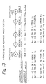
- the destination address always assumes the same value, e.g. NIL, as shown below in Fig. 13. This enables a common reception algorithm to be obtained at all nodes lying between the originating node and the destination node.
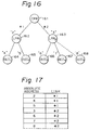
- Fig. 16 shows a conventional communication control system including a plurality of units 161 to 167.
- the unit 161 is a central processing unit (CPR); the units 162 and 163 are line processors (LPR1 and LPR2); and the units 164 - 167 are digital line control circuits (DLCC1 to DLCC4).
- Each unit conventionally has an absolute address. That is, in the figure, the units 161 to 167 respectively have absolute addresses "1" to "7".
- Each unit also has a translator, in other words a control data, in which the absolute address of each unit in the system is made to correspond to a link to be selected when the unit is a destination of a message.
- Fig. 17 is an example of the complex translator in the conventional central processing unit (CPR) 161.
- CPR central processing unit
- the remaining units 162 to 167 are provided with similar translators, respectively.
- the disadvantage of the above-described conventional communication system is that, when an additional unit such as a digital line control circuit (DLCC5) 168 is introduced into the system as shown in Fig. 16, the translators in all existing units must be changed. That is, in the translator in the central processing unit (CPR) 161, for example, the correspondence between the absolute address of the additional unit 168 and the link to be selected must be added. Similar modifications must be made to the remaining translators in the other units, and these modifications of the translators force a system designer to carry out very complex procedures.
- CPR central processing unit
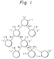
- Figure 1 is a diagram of an example of a communication system applied to the present invention.
- the communication system is an exchange system having a tree network in which there is one and only one path between any two nodes and including a plurality of units 1-1 to 1-n each having a communication facility.
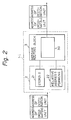
- the unit 1-i receives a signal message including a relative address consisting of an address of an originating unit and an address of a destination unit, and outputs a new relative address consisting of the address of an originating unit and the address of a destination unit.
- the unit 1-i includes a destination address forming block 2 and a signal message routing block 3.
- the destination address forming block 2 includes a storing unit 21 for storing adjacent-unit identifying numbers, and a relative address forming unit 22 for forming a relative address of the originating address and the destination address.
- the adjacent-unit identifying numbers are previously and fixedly determined to correspond to the unit 1-i under consideration.
- two units 1-2 and 1-3 are connected to the unit 1-1 through links #1 and #2 respectively.
- the address of the unit 1-1 is always determined as "1"; the address of the adjacent unit 1-2 is fixedly determined as, for example, "1", which fixedly corresponds to the link #1; and the address of the other adjacent unit 1-2 is also fixedly determined as, for example, "2", which fixedly corresponds to the link #2.
- the address of the unit 1-2 is "0"; the address of the adjacent unit 1-4 is “1"; and the address of the other adjacent unit is "2". Therefore, the storing unit 21 in the unit 1-1 stores the adjacent-unit identifying numbers "1" and "2".
- the destination address in the relative address is expressed by a set of adjacent-unit identifying numbers of the units provided along the communication path between the unit under consideration and the destination unit, including the destination unit and excluding the unit under consideration. For example, when the originating unit is unit 1-1 and the destination unit is unit 1-4, the destination address in relation to the unit 1-1 is expressed by a set "11"; and the destination address in relation to the unit 1-2 is expressed by a set "1".
- the message routing block 3 includes an address changing unit 30 by which, when the destination address in the received message is "0", the unit 1-i under consideration is determined to be the destination unit; and, when the received destination address is not "0", a link for transferring the message is selected, the received originating address is changed to a new originating address, in relation to the unit 1-i under consideration, and the received destinating address is changed to a new destination address in relation to the next stage unit.
- each unit employs relative addressses in relation to the unit under consideration, identify the other units, and since the address of the unit under consideration is determined to be "0" for every unit, the destination address received by the destination unit is always "0" for all units. Therefore, whether or not the received signal message is received by the destination unit can be determined by a fixed logic of wether or not the received destination address is "0".
- a unit which relays the signal message to the next-stage unit, selects a link and then changes the received destination address to a new destination address in relation to the next-stage unit. Similar selections and changes are effected step by step at each unit provided along the communication path, and thus the unit receiving the destination address "0" is determined to be the destination unit.
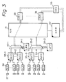
- Figure 3 is a block diagram showing an example of a communication control system applicable to an embodiment of the present invention.
- reference numeral 31 represents a network (NW); 32 a call processing processor (CPR); 33-1 and 33-2 multiplexing units; 34-1 and 34-2 line processing units (LPR); 35-1 to 35-4 digital line-control circuit units (DLCC); 36 a plurality of digital line circuits (DLC); 37 subscriber terminals; 38 common channel signaling equipment interfaces (CSEI); and 39 a common channel signaling equipment (CSE).
- NW network
- CPR call processing processor
- LPR line processing units
- LPR line processing units
- DLCC digital line-control circuit units
- DLC digital line circuits
- subscriber terminals 38 common channel signaling equipment interfaces (CSEI); and 39 a common channel signaling equipment (CSE).
- CSE common channel signaling equipment
- the network (NW) 31 performs an exchange operation on the outputs of the multiplexing units 33-1 and 33-2 under the control of the call processing processor 32.
- the multiplexing units 33-1 and 33-2 respectively multiplex the outputs of the digital line control circuits (DLCC) 35-1 and 35-2, and 35-3 and 35-4, under the control of the line processing units (LPR) 34-1 and 34-2.
- a plurality of the digital line circuits (DLC) 36 are connected to the inputs of each digital line control circuit units (DLCC).
- One of the subscriber terminals 37 is connected to the input of each digital line circuit (DLC).
- the outputs of the network (NW) 31 are connected through the common channel signaling equipment interface (CSEI) 38 to the common channel signaling equipment (CSE) 39.
- CSEI common channel signaling equipment interface
- the subjects of the communication between units, carried out in the embodiments of the present invention, are the call processing processor (CPR) 32, the line processors (LPR) 34-1 and 34-2, and the digital line control circuit units (DLCC) 35-1 to 35-4, all of which are represented in the figure by black triangles at the corners thereof.
- the transferring paths of the message are shown in the figure by dash lines.
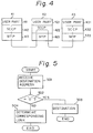
- Figure 4 is a diagram explaining the message transfer through the units which are the subject for the communication as shown in Fig. 3.
- 41, 42 and 43 are units which include user parts 411, 421 and 431, signal connection control parts (SCCP) 412, 422 and 432, and message transfer parts (MTP) 413, 423 and 433, respectively.
- SCCP signal connection control parts
- MTP message transfer parts
- the user parts 411, 421 and 431 are functional parts for transmitting messages to, and receiving messages from, the message transfer part. Plural user parts are provided for each function, such as a maintenance/operation program control or subscriber terminal connection control, to carry out a signal processing of the same function.
- the signal connection control parts (SCCP) 412, 422 and 432 are for carrying out message routing processings.
- the message transfer parts (MTP) 413, 423 and 433 carry out signal link controls in a inter-office communication.
- the CCITT No. 7 signal system is employed in this embodiment.
- the signal connection and control parts (SCCP) 412, 422 and 423 play an important role in the addressing and message routing.
- MTP message transferring parts
- control system for communication between units in the case of an inter-office communication is described.
- FIG. 5 is a flow chart explaining the operation at the signal connection control part (SCCP) 412, 422 or 432.
- the SCCP receives the destination address from the user part in the unit.
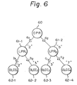
- FIG. 6 is a diagram explaining the control system for communication between units, according to the embodiment of the present invention.
- an office is provided with a call processing unit (CPR) 60, two line processing units (LPR) 61-1 and 61-2, and four digital line control circuit units (DLCC) 62-1 through 62-4.
- the communication is carried out in this example from the CPU to one of the units.
- a numeral, provided on the upper right of a circle representing each unit, is a relative address in relation to the original unit, i.e., the adjacent-unit identifying number.
- the adjacent-unit identifying number of the originating unit in relation to the receiving unit is not illustrated in the figure, but is, for example, "1" at each unit.
- the numeral "5" provided at the upper right of the LPR2 61-2 is the address of the LPR2 relative to the CPR, i.e., the adjacent-unit identifying number of the LPR2 relative to the CPR.
- the numeral "7" provided at the upper right of the DLCC4 is the address of the DLCC4 relative to the LPR2.
- the symbols "a i ", "b i ", and “c i ", of the links connecting the two units are link-identifying numbers representing the physically-accommodated positions of the communication paths.
- the signal connection control part (SCCP) in each unit has a simple translating table in which the correspondence between each adjacent-unit identifying number and the corresponding link identifying number is stored and memorized. By referring to the translating table, the originating address and the destination address are changed by a later described method.
- Figure 7 shows the translating tables provided in respective units shown in Fig. 6.
- the CPR stores two path-identifying numbers (P-No.) a1 and a2 and two adjacent-unit identifying numbers (AD-No.) "2" and "5" corresponding respectively to the numbers a1 and a2.
- P-No. path-identifying numbers
- AD-No. adjacent-unit identifying numbers
- the LPR1 stores three path-identifying numbers (P-No.) a1, b1 and b2 and three adjacent-unit identifying numbers (P-No.) "1", "2" and "3" corresponding to the numbers a1, b1 and b2, respectively.
- P-No. path-identifying numbers
- P-No. adjacent-unit identifying numbers
- the adjacent address "1" means that the originating unit for the LPR1 61-1 is the CPR 60 connected to the LPR1 61-1 via the link a1.
- the translating table in the LPR2 is similar to that in the LPR1.
- the DLCC1 through DLCC4 are end units, as shown in Fig. 6, and therefore, a single path is connected to each of the units. All units connected to the units DLCC1 through DLCC4 are originating units in relation to these units DLCC1 through DLCC4. Therefore, the adjacent-unit identifying numbers for these units DLCC1 through DLCC4 are "1".
- the SCCP may calculate the corresponding path-identifying number based on the received adjacent-unit identifying number, in accordance with a predetermined fixed logic. That is, the corresponding adjacent-unit identifying number is determined by adding a constant number to or by subtracting a constant number from the received adjacent-unit identifying number.
- FIG. 8 is a diagram explaining a modification of the originating address and the destination address when the CPR 60 in Fig. 6 is the originating unit and the DLCC4 62-4 in Fig. 6 is the destination unit.
- each of the units CPR 60, LPR2 61-3 and DLCC4 62-4 includes the user part *1, the signal connection control part including a destination address translating part *2, an originating address modification part *3, a destination address modification part *4, and the message transferring part (MTP) *5.
- MTP message transferring part
- Figure 9 is a flow chart showing a process flow in the originating address modification part *3; and Figure 10 is a flow chart showing a process flow in the destination address modification part *4.
- the user part *1 in the CPR 60 determines the destination address "57" and user data (step 101 in Fig. 10).
- the destination address "57" in this example is a set of adjacent-unit identifying numbers of all units provided on the path between the originating unit CPR 60 and the destination unit DLCC4 62-4, excluding the CPR 60 and including the DLCC4 62-4; i.e., in this example, a set of adjacent-unit identifying numbers of the units LPR2 61-2 and DLCC4 62-4.
- the user part *1 in the CPR 60 also determines the originating address to be Nil, which is all "0" (see Fig. 8), which means that the CPR 60 is an originating unit.
- the destination address "57”, the user data, and the originating address are transferred from the user part *1 to the destination address modification part *4 in the SCCP, as shown by the steps 102 and 103 in Fig. 10.
- a search is made in the translation table shown in Fig. 7 by using the head number "5" in the destination address as a key, to obtain the corresponding path-identifying number a2 , as shown by step 104 in Fig. 10. Then, as shown in step 105 in Fig. 10, the head number "5" is deleted from the destination address to obtain a new destination address "7".
- the message including the originating address Nil and the new destination address "7" is transferred through an interval 2 to the message transferring part *5 in the LPR2 61-2.
- the message transferring part *5 transfers the path-identifying number a2 and the message to the originating address modification part *3 in the LPR2 61-2 (steps 91 and 92 in Fig. 9).
- the originating address modification part *3 the originating address Nil is changed to "1", which is the adjacent-unit identifying number of the originating unit CPR 60 in relation to the LPR2 61-2. This change is effected by searching the translating table of the LPR2 shown in Fig.
- step 7 using the path-identifying number a2 as a key, to obtain the corresponding adjacent-unit identifying number "1", as shown in step 93 in Fig. 9; and then, as shown in step 94 in Fig. 9, the above-described adjacent-unit identifying number "1" and the originating address Nil is combined as a set indicating the new originating address.
- the thus-obtained originating address, destination address, and user data are transferred from the originating address modification part *3 to the destination address translation part *2 in the LPR2 61-2 (step 95 in Fig. 9).
- the destination address translation part *2 discriminates whether or not the received destination address is Nil. If the received destination address is Nil, the destination unit is determined to be the immediate receiving unit. If the received destination address is not Nil, the message is transferred to the next-stage unit. In the example shown in Fig. 8, the destination address received in the destination address translation part *2 in the LPR2 61-2 is "7", which is not Nil, and therefore, the part *2 in the LPR2 61-2 transfers the message to the destination address modification part *4.
- the destination address modification part *4 executes the steps 104 and 105 so that the destination address "7" is changed to Nil.
- the thus-obtained originating address "1" and the destination address Nil are transferred through an interval 4 and the message transferring part *5 in the DLCC4 62-4 to the originating address modification part *3 in the DLCC4 62-4, and steps 91 through 94 in Fig. 9 are executed as described before.
- the originating address is changed from "1" to "11". Since the destination address received by the destination address translation part *2 in the DLCC4 62-4 is Nil, the part *2 determines that the destination unit is the DLCC4 62-4, and thus the part *2 transfers the message data to the user part *1 in the DLCC4 62-4. In the user part *1, since the received originating address is "1", it is determined that the originating part is the CPR 60.
- the destination address translation unit *2 in each unit transfers the message if the received destination address is not Nil, and determines that the unit now receiving the message is the destination unit if the received destination address is Nil, the destination address translation unit *2 does not need to translate the absolute address as in the conventional system. Therefore, even when an additional unit is provided, the translation table in Fig. 7 in each unit does not need modification, except for the units adjacent to the additional unit.
- the most important feature of the present invention is the provision of the relative address to each unit in the office.
- the method of providing the relative addresses is described in a general way.
- the addressing of each unit is a relative addressing method in which the root of the tree is selected to be the unit which recognizes the addresses of the adjacent units.
- the addressing is carried out under the following conditions:
- connection path from the unit A to another unit B can be made in only one way, because of the tree structure.
- a plurality of units X1 , X2 , ..., and X n are provided along the connection path.
- the adjacent-unit identifying number of the unit X1 in relation to the unit A is a1
- the adjacent-unit identifying number of the unit X2 in relation to the unit X1 is a2
- the adjacent-unit identifying number of the unit X3 in relation to the unit X2 is a3
- the adjacent-unit identifying number of the unit B in relation to the unit X n is a n+1 .
- the address of the destination unit in relation to a unit is expressed by a set of adjacent-unit identifying numbers of all of the units along the communication path, excluding the unit under consideration and including the destination unit.
- the address of the unit B in relation to the unit A is a1 a2 ... a n a n+1
- the address of the unit B in relation to the unit X1 is a2 a3 ... a n a n+1
- the address of the unit B in relation to the unit X n is a n+1 .
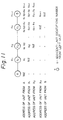
- Figs. 12A and 12B The address and the adjacent-unit identifying number of each unit determined in the above described method are illustrated as an example in Figs. 12A and 12B, in which units 121 to 128 are connected in a tree structure.
- Figure 12A shows the address of each unit in relation to a unit 122
- Fig. 12B shows the address of each unit in relation to a unit 105.
- the numeral provided at the upper right of each unit represents an adjacent-unit identifying number in relation to the key unit thereof.
- the numeral provided within the circle representing each unit is the address of the unit.
- the address of the unit 127 in relation to the unit 122 for example, is "33" because the adjacent-unit identifying number of the unit 125 is "3", and the adjacent-unit identifying number of the unit 127 is also "3".
- the addresses of the other units are determined in a similar way.
- the originating address and the destination address must be modified in relation to each unit, when a message is transferred through a plurality of units.
- the modification of the originating address and the destination address is executed as follows.
- the unit When a unit receives a message, the unit brings the fixed address "1" to be included into the originating address included in the received message.
- the originating address is modified according to the relationship between the pre-stage unit and the unit which is receiving the message.
- the originating address modification part * determines the corresponding adjacent-unit identifying number based on the translation table (see Fig. 7) or a fixed logic. Then, the determined adjacent-unit identifying number is included in the originating address in the received message.
- the adjacent-unit identifying number newly introduced into the originating address is placed adjacent to the head number of a set of a series of adjacent-unit identifying numbers representing the received originating address, that is, adjacent to the most newly provided numeral.
- Discrimination of whether the receiving unit is the destination unit or a relay unit provided along the path to the destination unit depends on whether or not the received destination address is Nil.
- the corresponding signal link connected to a unit to which the message is to be transferred is determined based on the translation table (see Fig. 7) or a fixed logic. Then, the top-end numeral is deleted from the destination address.
- the destination address is modified step by step. That is, the destination address in relation to the unit A is a1 a2 ... a n+1 ; is a2 a3 ... a n+1 in relation to the unit X1; and is Nil in relation to the unit B. Therefore, the unit B is the destination unit.
- the originating address of the unit A is modified step by step from Nil to b n+1 b n ... b2 b1.
- Figure 14 is a diagram explaining an example of the address modification.
- Nil is realized by Fillers.
- the Filler is an address signal expressed by all "0"s.
- the numeral is replaced by the Filler.
- a Filler replaces the numeral.
- the efficiency of the processing of the address modification is improved.
- the length of the destination address can be made the same as the length of the originating address.
- the length of the destination address is determined to be a necessary length for each message.
- Figure 15 is a diagram explaining the address modification in a response operation, according to an embodiment of the invention.
- the adjacent-unit identifying numbers of the CPU and LPR1 are "0" and "2", respectively.
- the adjacent-unit identifying number of the DLCC2 is "3". Therefore, in relation to the CPR, the destination address of the DLCC2 is "23".
- the CPR generates the destination address "23", and output the modified destination address "3" by deleting the head number "2" from the original destination address "23”.
- the LPR1 receives the modified destination address "3" via a link #1 and outputs the further modified destination address "0".
- the DLCC2 receives the destination address "0" via a link #2 and recognizes that the unit DLCC2 is the destination unit because the received destination address is "0".
- the originating address output from the CPU is "0", which is received by the LPR1 via the link #1.
- the LPR1 modifies the received originating address from "0" to "1”, and this address is then received by the DLCC2 via the link #2.
- the DLCC2 modifies the address to "11".
- the DLCC2 When the DLCC2 responds to the CPR, the DLCC2 sends response information to the CPR.
- the response information includes a response destination address having the CPR as a destination, and a response originating address.
- the response destination address at the destination unit DLCC2 is made equal to the received originating address "11" in this example.
- the DLCC2 modifies the response destination address "11" to "1” and sends the modified address to the LPR1 via the link #2.
- the LPR1 modifies the received response destination address "1" to "0” and sends the modified address to the CPR via the link #1.
- the CPR receives the response destination address "0".
- the response originating address at the destination unit DLCC2 is "0", which is sent via the link #2 to the LPR1.
- the LPR1 modifies the received response originating address "0" to "3” based on the translation table by using the link #2 as a key or based on a fixed logic.
- the modified response originating address "3" is sent via the link #1 to the CPR.
- the CPR modifies the received address "3" to "23" based on the table or the fixed logic by using the link #1 as a key.
- a relative address is provided for each unit subject to the communication, and routing is executed based on the relative address.
- whether or not the received message should be terminated at the unit under consideration is determined by merely depending on whether or not the received destination address is Nil. Therefore, the conventional complex translation of the destination address is not needed.
- the correspondence between each unit and the line does not need modification except for the units adjacent to the newly introduced unit or office. Thus, the system designer can perform the system design very easily.
- the present invention is not restricted to the application to communication between units in an exchange office, but is also applicable to communication betwen exchange offices.
Landscapes
- Engineering & Computer Science (AREA)
- Computer Networks & Wireless Communication (AREA)
- Signal Processing (AREA)
- Business, Economics & Management (AREA)
- Emergency Management (AREA)
- Physics & Mathematics (AREA)
- General Physics & Mathematics (AREA)
- Data Exchanges In Wide-Area Networks (AREA)
- Exchange Systems With Centralized Control (AREA)
- Small-Scale Networks (AREA)
Claims (8)
- Kommunikationssystem mit einem Baumnetzwerk einschließlich einer Vielzahl von Einheiten (1-1, ..., 1-n) mit jeweils einer Kommunikationsmöglichkeit zur Kommunikation zwischen einer Ursprungseinheit (A) und einer Bestimmungseinheit (B) über eine Vielzahl von Relaiseinheiten (X₁, ..., Xn) unter Benutzung relativer Adressen;
dadurch gekennzeichnet, daß
jede der Einheiten (1-1, ..., 1-n) umfaßt:- eine Bestimmungsadressen-Bildungseinrichtung (2) einschließlich einer Speichereinrichtung (21) zum Speichern von Nachbareinheit-Identifikationsnummern aller anliegender Einheiten, welche die relativen Adressen sind, und eine Relativadressen-Bildungseinrichtung (22) zum Bilden einer Relativadresse für eine Bestimmungsadresse, dargestellt durch einen Satz von Nachbareinheit-Identifkationsnummern aller Einheiten, welche vorgesehen sind auf dem Kommunikationsweg zwischen der Ursprungseinheit (A) und der Bestimmungseinheit (B) und einer Nulldaten-Ursprungsadresse;- eine Signalnachricht-Wegführungseinrichtung (3) zum Empfangen der Bestimmungsadresse und der Ursprungsadresse von einer oberen anliegenden Einheit oder von der Bestimmungsadressen-Bildungseinrichtung (2), welche umfaßt:- eine Bestimmungs-Entscheidungseinrichtung zum Bestimmen ob die empfangene Bestimmungsadresse Daten beinhaltet zum Entscheiden, daß die Einheit, die die Bestimmungsadresse empfängt, die Bestimmungseinheit ist, wenn die empfangene Bestimmungsadresse Nulldaten enthält;- eine Adressenänderungseinrichtung, die betriebsmäßig verbunden ist mit der Bestimmungs-Entscheidungseinrichtung zum Ändern der empfangenen Ursprungsadresse in eine neue Ursprungsadresse durch Hinzufügen der anliegenden Ursprungsadresse zu der empfangenen Ursprungsadresse und zum Ändern der empfangenen Bestimmungsadresse in eine neue Bestimmungsadresse durch Löschen der anliegenden Bestimmungsadresse einer oberen Einheit neben der Einheit, welche die Bestimmungsadresse empfängt, aus der empfangenen Bestimmungsadresse; und- eine Wegauswahleinrichtung zum Wählen eines Weges zum Übertragen der geänderten Ursprungsadresse und der geänderten Bestimmungsadresse an eine niedrige anliegende Einheit basierend auf der geänderten Bestimmungsadresse, wenn die Bestimmungsadresse Nicht-Nulldaten enthält; und- eine Einrichtung zum Übertragen der geänderten Ursprungsadresse und Bestimmungsadresse an die niedrigere anliegende Einheit. - Kommunikationssystem nach Anspruch 1,
dadurch gekennzeichnet, daß das Kommunikationssystem ein Fernvermittlungssystem ist und die Vielzahl von Einheiten (1-1 bis 1-n) eine Rufverarbeitungseinheit (32) zum Steuern eines Netzwerks (31) enthalten; eine Leitungsverarbeitungseinheit (34-1, 34-2) unter der Steuerung der Rufverarbeitungseinheit (32) vorgesehen ist entsprechend einer Vielzahl von Fernsprechteilnehmerleitungen (37); und eine Leitungssteuerungseinheit (35-1, 35-2, 35-3, 35-4) unter der Steuerung der Leitungsverarbeitungseinheit (34-1, 34-2) zum Steuern jeder der Fernsprechteilnehmerleitungen (37) vorgesehen ist;
wobei die Leitungsverarbeitungseinheit (34-1, 34-2) die Leitungssteuerungseinheit (35-1, 35-2, 35-3, 35-4) und die Rufverarbeitungseinheit (32) verbunden sind über Verbindungen zur Kommunikation; und
eine Kommunikation zwischen der Rufverarbeitungseinheit (32) und der Leitungsverarbeitungseinheit (34-1, 34-2) oder zwischen der Rufverarbeitungseinheit (32) und der Leitungssteuerungseinheit (35-1, 35-2, 35-3, 35-4) bewirkt wird unter Benutzung der relativen Adressen. - Kommunikationssystem nach Anspruch 2,
dadurch gekennzeichnet, daß die Beziehung zwischen der Verbindung, welche vorgesehen ist zwischen der Rufverarbeitungseinheit (32) und der Leitungsverarbeitungseinheit (34-1, 34-2) oder zwischen der Rufverarbeitungseinheit (32) und der Leitungssteuerungseinheit (35-1, 35-2, 35-3, 35-4), und die relativen Adressen bestimmt werden unter Benutzung einer Übersetzungstabelle. - Kommunikationssystem nach Anspruch 2,
dadurch gekennzeichnet, daß die Beziehung zwischen der Verbindung, welche vorgesehen ist zwischen der Rufverarbeitungseinheit (32) und der Leitungsverarbeitungseinheit (34-1, 34-2) oder zwischen der Rufverarbeitungseinheit (32) und der Leitungssteuerungseinheit (35-1, 35-2, 35-3, 35-4), und die relativen Adressen vorgesehen werden mit einer bestimmten Logik, wodurch die Verbindungsnummer des durch die Wegauswahleinrichtung gewählten Weges bestimmt wird durch Addieren eines konstanten Wertes zu oder durch Subtrahieren eines konstanten Wertes von den Relativadressen. - Kommunikationssystem nach einem der vorhergehenden Ansprüche,
dadurch gekennzeichnet, daß jede der Einheiten eine Antworteinrichtung umfaßt zum Senden von Antwortinformation an die Ursprungseinheit, wobei die Antwortinformation eine Antwortbestimmungsadresse zum Spezifizieren der Ursprungsadresse als eine Antwortbestimmung enthält, wobei die Antwortbestimmungsadresse gleich der empfangenen Ursprungsadresse ist. - Kommunikationssystem nach Anspruch 5,
dadurch gekennzeichnet, daß die Antwortbestimmungsadresse gebildet wird durch einen Satz von "1"en, wobei die Anzahl der "1"en gleich der Anzahl von Einheiten ist zwischen der Antworteinheit und der Ursprungseinheit, ausschließlich der Antworteinheit und einschließlich der Ursprungseinheit. - Kommunikationssystem nach Anspruch 5 oder 6,
dadurch gekennzeichnet, daß die Antwortinformation eine Antwort-Ursprungsadresse und eine empfangene Verbindungsnummer umfaßt, wobei die Antwort-Ursprungsadresse, die die die Bestimmungseinheit erzeugt, "0" ist und jede der Einheiten, die die Signalnachricht weiterleiten, eine Antwort-Ursprungsadressen-Änderungseinrichtung umfaßt zum Erzeugen einer modifizierten Antwort-Ursprungsadresse durch Addieren einer Zahl zu der empfangenen Antwort-Ursprungsadresse, wobei die Nummer erhalten wird von einer Übersetzungstabelle zum Speichern einer Übereinstimmung zwischen der empfangenen Verbindungsnummer und der Nummer und die Nummer und die empfangene Verbindungsnummer benutzt werden als ein Schlüssel zur Übersetzung. - Kommunikationssystem nach einem der Ansprüche 5 oder 6,
dadurch gekennzeichnet, daß die Antwortinformation eine Antwort-Ursprungsadresse und eine Empfangsnummer beinhaltet, wobei die Antwort-Ursprungsadresse, die die Bestimmungseinheit erzeugt "0" ist, und jede der Einheiten zum Weiterleiten der Signalnachricht, eine Anwort-Usprungsadressen-Modifikationseinrichtung umfaßt zum Erzeugen einer modifizierten Antwort-Ursprungsadresse durch Addieren einer konstanten Nummer zu empfangen von der Ursprungsadresse, wobei die Nummer erhalten wird durch Addieren einer konstanten Zahl zu oder Subtrahieren einer konstanten Zahl von der empfangenen Verbindungsnummer, welche in der Antwortinformation enthalten ist.
Applications Claiming Priority (2)
| Application Number | Priority Date | Filing Date | Title |
|---|---|---|---|
| JP62003309A JPH0634537B2 (ja) | 1987-01-12 | 1987-01-12 | 装置間通信制御方式 |
| JP3309/87 | 1987-01-12 |
Publications (3)
| Publication Number | Publication Date |
|---|---|
| EP0275076A2 EP0275076A2 (de) | 1988-07-20 |
| EP0275076A3 EP0275076A3 (en) | 1990-10-24 |
| EP0275076B1 true EP0275076B1 (de) | 1994-06-15 |
Family
ID=11553751
Family Applications (1)
| Application Number | Title | Priority Date | Filing Date |
|---|---|---|---|
| EP88100309A Expired - Lifetime EP0275076B1 (de) | 1987-01-12 | 1988-01-12 | Steuerungssystem zur Verbindung zwischen Einheiten |
Country Status (6)
| Country | Link |
|---|---|
| US (1) | US5077554A (de) |
| EP (1) | EP0275076B1 (de) |
| JP (1) | JPH0634537B2 (de) |
| CN (1) | CN1008875B (de) |
| CA (1) | CA1316242C (de) |
| DE (1) | DE3850128T2 (de) |
Families Citing this family (14)
| Publication number | Priority date | Publication date | Assignee | Title |
|---|---|---|---|---|
| US5287343A (en) * | 1991-02-25 | 1994-02-15 | Matsushita Electric Works, Ltd. | Network administration system |
| US5825865A (en) * | 1991-10-04 | 1998-10-20 | Motorola, Inc. | Temporary message routing and destination selection |
| GB2268374A (en) * | 1992-06-23 | 1994-01-05 | Ibm | Network addressing |
| JP3170095B2 (ja) * | 1993-04-14 | 2001-05-28 | 富士通株式会社 | 情報検索システム |
| US5721728A (en) * | 1995-12-21 | 1998-02-24 | Lucent Technologies Inc. | Network node testing method and apparatus |
| FI103544B1 (fi) * | 1996-03-25 | 1999-07-15 | Nokia Telecommunications Oy | Menetelmä osoitteiden määrittämiseksi tietoliikenneverkon solmuissa |
| EP1008254B1 (de) * | 1997-03-17 | 2008-06-18 | Ge-Harris Railway Electronics L.L.C. | Nachrichtenübertragungssystem für verbundene netzwerke mit linearer topologie |
| JP3222086B2 (ja) * | 1997-04-07 | 2001-10-22 | 矢崎総業株式会社 | ツリー構造のアドレス設定方法及びそのシステム |
| US6014084A (en) * | 1997-05-19 | 2000-01-11 | Pittway Corporation | Electronic self-locating system and method |
| US6266694B1 (en) * | 1997-06-19 | 2001-07-24 | Nortel Networks Limited | Architecture for network manager |
| US6801524B2 (en) | 2000-01-31 | 2004-10-05 | Sonim Technologies, Inc. | System for dispatching information packets and method therefor |
| US20040039839A1 (en) * | 2002-02-11 | 2004-02-26 | Shivkumar Kalyanaraman | Connectionless internet traffic engineering framework |
| US8504629B2 (en) * | 2010-07-01 | 2013-08-06 | Plantronics, Inc. | Connection device and protocol |
| US9481348B2 (en) * | 2012-09-20 | 2016-11-01 | Wabtec Holding Corp. | System and method for addressing a pneumatic emergency in a helper locomotive |
Family Cites Families (9)
| Publication number | Priority date | Publication date | Assignee | Title |
|---|---|---|---|---|
| US4250489A (en) * | 1978-10-31 | 1981-02-10 | Westinghouse Electric Corp. | Distribution network communication system having branch connected repeaters |
| US4237447A (en) * | 1979-05-02 | 1980-12-02 | Burroughs Corporation | Speed independent selector switch for digital communication networks |
| US4284976A (en) * | 1979-06-07 | 1981-08-18 | Ford Motor Company | Interface between communication channel segments |
| DE3036740A1 (de) * | 1980-09-29 | 1982-05-13 | Siemens AG, 1000 Berlin und 8000 München | Universelles digitalnetz zur paketvermittelten informationsuebertragung |
| US4427968A (en) * | 1981-04-09 | 1984-01-24 | Westinghouse Electric Corp. | Distribution network communication system with flexible message routes |
| US4675668A (en) * | 1982-12-30 | 1987-06-23 | Sharp Kabushiki Kaisha | Data transmission system over building wiring |
| NL8401443A (nl) * | 1984-05-07 | 1985-12-02 | Philips Nv | Telecommunicatiesysteem in het bijzonder een telefoonsysteem. |
| US4796023A (en) * | 1986-12-05 | 1989-01-03 | King Robert E | Stabilized binary tree protocol |
| US4823111A (en) * | 1988-02-22 | 1989-04-18 | The Mitre Corporation | Landmark hierarchy method for routing signals in a communications network |
-
1987
- 1987-01-12 JP JP62003309A patent/JPH0634537B2/ja not_active Expired - Fee Related
-
1988
- 1988-01-11 CA CA000556255A patent/CA1316242C/en not_active Expired - Fee Related
- 1988-01-12 DE DE3850128T patent/DE3850128T2/de not_active Expired - Fee Related
- 1988-01-12 US US07/142,998 patent/US5077554A/en not_active Expired - Lifetime
- 1988-01-12 EP EP88100309A patent/EP0275076B1/de not_active Expired - Lifetime
- 1988-01-12 CN CN88100083A patent/CN1008875B/zh not_active Expired
Also Published As
| Publication number | Publication date |
|---|---|
| DE3850128D1 (de) | 1994-07-21 |
| EP0275076A2 (de) | 1988-07-20 |
| CA1316242C (en) | 1993-04-13 |
| EP0275076A3 (en) | 1990-10-24 |
| JPH0634537B2 (ja) | 1994-05-02 |
| JPS63172589A (ja) | 1988-07-16 |
| DE3850128T2 (de) | 1994-11-10 |
| US5077554A (en) | 1991-12-31 |
| CN88100083A (zh) | 1988-08-17 |
| CN1008875B (zh) | 1990-07-18 |
Similar Documents
| Publication | Publication Date | Title |
|---|---|---|
| EP0275076B1 (de) | Steuerungssystem zur Verbindung zwischen Einheiten | |
| KR100438632B1 (ko) | 가상 경로기반 스태틱 루팅 | |
| JP2739023B2 (ja) | パケツト伝送システム | |
| US5487064A (en) | Network layer packet structure | |
| EP1755295B1 (de) | Verfahren und Systeme zur Übermittlung von SS7-Nachrichten | |
| EP0308449B1 (de) | Nachrichtenübertragung in einem multiplexsystem | |
| KR960007672B1 (ko) | 패킷된 디지탈 정보의 전송 방법 및 스위칭 노드 | |
| EP0705012A2 (de) | Rechnernetzwerkdurchschaltvermittlung | |
| CA2329367C (en) | Distributed switch and connection control arrangement and method for digital communications network | |
| EP1192791B1 (de) | Voip unter benutzung von ss7 zeichengabe und zusammenarbeit von ip knoten mit zeichengabepunkten | |
| WO1986003355A1 (en) | Self-routing packets with stage address identifying fields | |
| JPH0629974A (ja) | 同報通信方法 | |
| JP3449541B2 (ja) | データパケット転送網とデータパケット転送方法 | |
| US6097727A (en) | Methods, systems and computer program products for end-to-end route selection in compound wide/local area networks | |
| US5289467A (en) | Manhattan street network with loop architecture | |
| US20050005029A1 (en) | System and method of accessing and transmitting different data frames in a digital transmission network | |
| JPH11298531A (ja) | 信号伝送方法 | |
| JP3713825B2 (ja) | 情報処理装置、通信システムおよびその方法 | |
| US5748625A (en) | Inter-LAN connection method using ISDN | |
| KR20030054547A (ko) | 에이티엠 교환기를 이용한 타사 이동 교환기간의 소프트핸드오프 처리 장치 및 방법 | |
| JP2967424B2 (ja) | 異方向リング型パケット通信システムの伝送経路接続制御方法 | |
| KR100311226B1 (ko) | 광대역 종합정보통신망 교환노드에서 중계 신호 프로토콜결정 방법 | |
| JP3255238B2 (ja) | 通信制御処理装置 | |
| EP1111847B1 (de) | System und Verfahren zur Ethernet-Verbindung einesTelekommunikationsnetzwerksknotens | |
| KR100241339B1 (ko) | 비동기 전송모드 교환기에서 신호 연결 제어부의 호환성을 위한메시지 유형 변환방법 |
Legal Events
| Date | Code | Title | Description |
|---|---|---|---|
| PUAI | Public reference made under article 153(3) epc to a published international application that has entered the european phase |
Free format text: ORIGINAL CODE: 0009012 |
|
| AK | Designated contracting states |
Kind code of ref document: A2 Designated state(s): DE FR GB SE |
|
| PUAL | Search report despatched |
Free format text: ORIGINAL CODE: 0009013 |
|
| AK | Designated contracting states |
Kind code of ref document: A3 Designated state(s): DE FR GB SE |
|
| 17P | Request for examination filed |
Effective date: 19901214 |
|
| 17Q | First examination report despatched |
Effective date: 19921222 |
|
| GRAA | (expected) grant |
Free format text: ORIGINAL CODE: 0009210 |
|
| AK | Designated contracting states |
Kind code of ref document: B1 Designated state(s): DE FR GB SE |
|
| REF | Corresponds to: |
Ref document number: 3850128 Country of ref document: DE Date of ref document: 19940721 |
|
| ET | Fr: translation filed | ||
| EAL | Se: european patent in force in sweden |
Ref document number: 88100309.9 |
|
| PLBE | No opposition filed within time limit |
Free format text: ORIGINAL CODE: 0009261 |
|
| STAA | Information on the status of an ep patent application or granted ep patent |
Free format text: STATUS: NO OPPOSITION FILED WITHIN TIME LIMIT |
|
| 26N | No opposition filed | ||
| REG | Reference to a national code |
Ref country code: GB Ref legal event code: IF02 |
|
| PGFP | Annual fee paid to national office [announced via postgrant information from national office to epo] |
Ref country code: SE Payment date: 20030107 Year of fee payment: 16 |
|
| PGFP | Annual fee paid to national office [announced via postgrant information from national office to epo] |
Ref country code: GB Payment date: 20030108 Year of fee payment: 16 |
|
| PGFP | Annual fee paid to national office [announced via postgrant information from national office to epo] |
Ref country code: FR Payment date: 20030110 Year of fee payment: 16 |
|
| PGFP | Annual fee paid to national office [announced via postgrant information from national office to epo] |
Ref country code: DE Payment date: 20030123 Year of fee payment: 16 |
|
| PG25 | Lapsed in a contracting state [announced via postgrant information from national office to epo] |
Ref country code: GB Free format text: LAPSE BECAUSE OF NON-PAYMENT OF DUE FEES Effective date: 20040112 |
|
| PG25 | Lapsed in a contracting state [announced via postgrant information from national office to epo] |
Ref country code: SE Free format text: LAPSE BECAUSE OF NON-PAYMENT OF DUE FEES Effective date: 20040113 |
|
| PG25 | Lapsed in a contracting state [announced via postgrant information from national office to epo] |
Ref country code: DE Free format text: LAPSE BECAUSE OF NON-PAYMENT OF DUE FEES Effective date: 20040803 |
|
| EUG | Se: european patent has lapsed | ||
| GBPC | Gb: european patent ceased through non-payment of renewal fee |
Effective date: 20040112 |
|
| PG25 | Lapsed in a contracting state [announced via postgrant information from national office to epo] |
Ref country code: FR Free format text: LAPSE BECAUSE OF NON-PAYMENT OF DUE FEES Effective date: 20040930 |
|
| REG | Reference to a national code |
Ref country code: FR Ref legal event code: ST |