EP0275103A2 - Vorrichtung zur automatischen Montage von Bauteilen - Google Patents
Vorrichtung zur automatischen Montage von Bauteilen Download PDFInfo
- Publication number
- EP0275103A2 EP0275103A2 EP88100458A EP88100458A EP0275103A2 EP 0275103 A2 EP0275103 A2 EP 0275103A2 EP 88100458 A EP88100458 A EP 88100458A EP 88100458 A EP88100458 A EP 88100458A EP 0275103 A2 EP0275103 A2 EP 0275103A2
- Authority
- EP
- European Patent Office
- Prior art keywords
- electronic parts
- positioning
- tipped
- suction nozzles
- suction
- Prior art date
- Legal status (The legal status is an assumption and is not a legal conclusion. Google has not performed a legal analysis and makes no representation as to the accuracy of the status listed.)
- Withdrawn
Links
- 239000000758 substrate Substances 0.000 claims abstract description 28
- 230000002093 peripheral effect Effects 0.000 claims abstract description 11
- 230000001360 synchronised effect Effects 0.000 claims description 2
- 238000004891 communication Methods 0.000 description 24
- 230000006854 communication Effects 0.000 description 24
- 239000012298 atmosphere Substances 0.000 description 9
- 230000004308 accommodation Effects 0.000 description 8
- 238000010276 construction Methods 0.000 description 7
- 230000033001 locomotion Effects 0.000 description 5
- 230000000694 effects Effects 0.000 description 4
- 238000012856 packing Methods 0.000 description 4
- 238000001514 detection method Methods 0.000 description 3
- 230000000875 corresponding effect Effects 0.000 description 2
- 238000006073 displacement reaction Methods 0.000 description 2
- 239000000428 dust Substances 0.000 description 2
- 238000004806 packaging method and process Methods 0.000 description 2
- 101150034459 Parpbp gene Proteins 0.000 description 1
- 230000005856 abnormality Effects 0.000 description 1
- 239000003990 capacitor Substances 0.000 description 1
- 238000012790 confirmation Methods 0.000 description 1
- 230000003287 optical effect Effects 0.000 description 1
- 230000003245 working effect Effects 0.000 description 1
Images








Classifications
-
- H—ELECTRICITY
- H05—ELECTRIC TECHNIQUES NOT OTHERWISE PROVIDED FOR
- H05K—PRINTED CIRCUITS; CASINGS OR CONSTRUCTIONAL DETAILS OF ELECTRIC APPARATUS; MANUFACTURE OF ASSEMBLAGES OF ELECTRICAL COMPONENTS
- H05K13/00—Apparatus or processes specially adapted for manufacturing or adjusting assemblages of electric components
-
- H—ELECTRICITY
- H05—ELECTRIC TECHNIQUES NOT OTHERWISE PROVIDED FOR
- H05K—PRINTED CIRCUITS; CASINGS OR CONSTRUCTIONAL DETAILS OF ELECTRIC APPARATUS; MANUFACTURE OF ASSEMBLAGES OF ELECTRICAL COMPONENTS
- H05K13/00—Apparatus or processes specially adapted for manufacturing or adjusting assemblages of electric components
- H05K13/04—Mounting of components, e.g. of leadless components
- H05K13/0404—Pick-and-place heads or apparatus, e.g. with jaws
- H05K13/0413—Pick-and-place heads or apparatus, e.g. with jaws with orientation of the component while holding it; Drive mechanisms for gripping tools, e.g. lifting, lowering or turning of gripping tools
-
- H—ELECTRICITY
- H05—ELECTRIC TECHNIQUES NOT OTHERWISE PROVIDED FOR
- H05K—PRINTED CIRCUITS; CASINGS OR CONSTRUCTIONAL DETAILS OF ELECTRIC APPARATUS; MANUFACTURE OF ASSEMBLAGES OF ELECTRICAL COMPONENTS
- H05K13/00—Apparatus or processes specially adapted for manufacturing or adjusting assemblages of electric components
- H05K13/04—Mounting of components, e.g. of leadless components
- H05K13/0404—Pick-and-place heads or apparatus, e.g. with jaws
- H05K13/0408—Incorporating a pick-up tool
- H05K13/041—Incorporating a pick-up tool having multiple pick-up tools
-
- Y—GENERAL TAGGING OF NEW TECHNOLOGICAL DEVELOPMENTS; GENERAL TAGGING OF CROSS-SECTIONAL TECHNOLOGIES SPANNING OVER SEVERAL SECTIONS OF THE IPC; TECHNICAL SUBJECTS COVERED BY FORMER USPC CROSS-REFERENCE ART COLLECTIONS [XRACs] AND DIGESTS
- Y10—TECHNICAL SUBJECTS COVERED BY FORMER USPC
- Y10T—TECHNICAL SUBJECTS COVERED BY FORMER US CLASSIFICATION
- Y10T29/00—Metal working
- Y10T29/53—Means to assemble or disassemble
- Y10T29/5313—Means to assemble electrical device
- Y10T29/53174—Means to fasten electrical component to wiring board, base, or substrate
- Y10T29/53178—Chip component
-
- Y—GENERAL TAGGING OF NEW TECHNOLOGICAL DEVELOPMENTS; GENERAL TAGGING OF CROSS-SECTIONAL TECHNOLOGIES SPANNING OVER SEVERAL SECTIONS OF THE IPC; TECHNICAL SUBJECTS COVERED BY FORMER USPC CROSS-REFERENCE ART COLLECTIONS [XRACs] AND DIGESTS
- Y10—TECHNICAL SUBJECTS COVERED BY FORMER USPC
- Y10T—TECHNICAL SUBJECTS COVERED BY FORMER US CLASSIFICATION
- Y10T29/00—Metal working
- Y10T29/53—Means to assemble or disassemble
- Y10T29/5313—Means to assemble electrical device
- Y10T29/53191—Means to apply vacuum directly to position or hold work part
-
- Y—GENERAL TAGGING OF NEW TECHNOLOGICAL DEVELOPMENTS; GENERAL TAGGING OF CROSS-SECTIONAL TECHNOLOGIES SPANNING OVER SEVERAL SECTIONS OF THE IPC; TECHNICAL SUBJECTS COVERED BY FORMER USPC CROSS-REFERENCE ART COLLECTIONS [XRACs] AND DIGESTS
- Y10—TECHNICAL SUBJECTS COVERED BY FORMER USPC
- Y10T—TECHNICAL SUBJECTS COVERED BY FORMER US CLASSIFICATION
- Y10T29/00—Metal working
- Y10T29/53—Means to assemble or disassemble
- Y10T29/5313—Means to assemble electrical device
- Y10T29/53261—Means to align and advance work part
Definitions
- the present invention relates to an automatic mounting apparatus for electronic parts, and more particularly, to an automatic mounting apparatus provided with a part adjusting function, in automatically positioning and mounting on a print substrate tipped electronic parts (hereinafter referred to as tipped part(s)), for example, such as resistors, capacitors or transisters, by which the tipped parts may be positioned and adjusted according to the form of the tipped parts of different sizes and shapes.
- tipped part(s) for example, such as resistors, capacitors or transisters
- the electronic parts automatic mounting apparatus of this kind has been known, for example, as disclosed in Japanese Utility Model Application Laid-Open No. 57-48672 previously filed by the present applicant, in which a tipped part seal-in tape wound and accommodated in a tape reel is intermittently drawn and delivered, the tipped parts are supplied to a fixed part-removing station, the tipped parts supplied to the part-removing station are suctioned by a plurality of suction nozzles which are provided mov ably up and down below the lower portion of the peripheral edge in the circumferential direction of an intermittently rotating turntable, and the tipped parts are mounted on a table which is movable and controllable in all directions (in an X-Y direction) while positioning and defining the tipped parts suctioned and held by the suction nozzles.
- the positioning apparatuses for the tipped parts suctioned and held by the suction nozzles in the automatic mounting apparatus as described have been proposed, for exaample, as disclosed in Japanese Patent Application Laid-Open No. 56-24,997 and Japanese Utility Model Application Laid-Open No. 58-136,288 Specifications, in which the direction of the tipped parts are positioned according to the arranging mode thereof onto a print substrate by urging the tipped parts from all directions with use of positioning pawl members in the fixed positioning station, and as disclosed in Japanese Patent Application Laid-Open No.
- a V-shaped notched groove 201 is formed at the end of a suction nozzle 200 to suction and hold a cylindrical tipped part, when a center between the V-shaped notched groove 201 at the end of the suction nozzle 200 and each of the positioning pawl members 203 and 204 is deviated from each other, the cylindrical tipped part 202 tends to be positioned by the positioning pawl members 203 and 204 under the unstable state wherein the tipped part 202 is not fitted in the V-shaped notched groove 201.
- the tipped part 202 when the tipped part 202 is released from each of the positioning pawl members 203 and 204 after completion of the positioning, the tipped part 202 sometimes becomes deviated due to the movement thereof in such a way that the tipped part 202 is fitted into the notched groove 201 under the influence of the suction force of the suction nozzle 200. For this reason, difficult adjustment by which the direction of the notched groove 201 at the end of the suction nozzle and the direction of each of the positioning pawl members 203 and 204 are brought into precise coincidence has to be carried out for each suction nozzle, and moreover, the apparatus per se need be replaced according to the form of tipped parts of different sizes and shapes.
- the present invention overcomes inconveniences in severelyherent in the above-described conventional electronic parts automatic mounting apparatus. It is a principal object of the present invention to provide an electronic parts automatic mounting apparatus in which a plurality of suction nozzles are provided on the peripheral edge of an intermittently rotating turntable, tip-like electronic parts delivered from a part supply portion are suctioned and held by these suction nozzles, and electronic parts being transferred, positioned and mounted on a print substrate placed on an X-Y table by the intermittent rotation of said turntable, said apparatus being provided with part adjusting means for subjecting the electronic parts suctioned and held by said suction nozzles to various stepwise adjusting works at a plurality of working stations provided on the way of transferring thereof, wherein said part adjusting means comprises a plurality of positioning working units for positioning electronic parts arranged in correspondence to one part positioning station of the working units, each of said positioning working units being selectively actuated according to the form of electronic parts having different sizes and shapes. With this arrangement, the positioning of the tipped parts
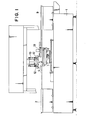
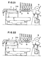
- reference numeral 1 designates a base bed, 2 a supply conveyor for placing thereon a print substrate to supply and transfer it, and 3 a transfer device for transferring the print substrate on the supply conveyor 2 to an XY table 4.
- the device 3 is rotatably supported at one end by means of a support shaft 5 and can be moved along a rail 6.
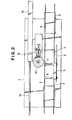
- a pair of feed pawls 7 and 8 are rotated about said support shaft 5 and moved downward, and the device 3 moves rightward as viewed in FIG. 2.
- This movement causes the print substrate on the XY table 4 to be moved rightward by one pawl 7, whereas at the same time, the other pawl 8 serves to transfer the print substrate on the supply conveyor onto the XY table 4.
- XY table 4 with the print substrate placed on said table from the transfer device 3 is moved downward (which assumes the state shown in FIG. 22 from FIG. 21) by means of drive means not shown whereby the XY table 4 may be moved in all directions.
- Numeral 10 designates a turntable, which is mounted on an index unit 11 rotated by a drive motor not shown and is intermittently rotated.
- eighteen (18) suction head 12 are provided movably upward and downward at equal intervals.
- Numeral 13 designates a part supply bed capable of being moved along a laterally extending rail 14, on which part supply bed are juxtaposed a plurality of tape supply units (supply means) 18 designed so that a tape 16 accommodating therein tip-like electronic parts or tipped parts 15 at equal intervals is wound about a reel 17 and the tape 16 is delivered every part array pitch.
- Numeral 19 designates a positioning device for positioning the tipped part 15 prior to mounting it to the print substrate.
- the XY table 4 when moved downward can be moved in the direction of X- and Y axes below the turntable 10 and the positioned device 19 (see FIG. 23).
- Numeral 20 designates a cylindrical cam member for guiding a hollow cylindrical table suspended and secured to a mounting bed 11A of the index unit 11 so as to surround the upper portion of a cylindrical portion 21 formed above the turntable 10.
- the cam member 20 is formed at its peripheral side at the lower end with a cam 22 over the substantially entire periphery thereof, a roller 24 as a sliding portion provided onthe upper end of each of the suction heads 12 is rotated while being urged against the upper surface of the cam 22 by means of a spring 23, and the each of the suction heads 12 are moved upward and downward along a profile of the cam 22 and rotated along with the turntable 10.
- each of the suction heads 12 are stood upright a pair of guide rods 25 which vertically movably extend through the turntable 10, and a mounting member 26 with a roller 24 rotatably provided thereon is secured to the upper end of the rod 25.
- each of the suction heads 12 are vertically movable supported on the turntable 10.
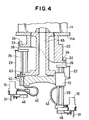
- a cylindrical body 27 is rotatably held through a bearing 29 within upper and lower blocks 28, and a gear 30 formed with teeth in the peripheral side integral with the cylindrical body 27 is meshed with a drive mechanism not shown from the exterior for rotation.
- Numeral 31 designates a suction nozzle interiorly formed with an intake passage 32 in communication with a vaccum pump as a vacuum source not shown to enable suctioning the tipped part 15 at the lower end thereof, the nozzle 31 being guided by means of a ball bearing 33 for upward and downward movements and rotation.
- a dust-removing filter 35 that may be installed or removed from an upper opening 34, and a filter case 37 having a space 36 is secured to the lower portion of the filter 35.
- the filter case 37 can be formed integral with the suction nozzle 31.
- Numeral 38 designates a filter accommodating portion detachably mounted on the upper portion of the cylindrical body 27 to form an accommodation chamber 40 whose interior is in the form of a cavity to receive the filter 35 and a spring 39. Accordingly, when the filter 35 is replaced, the filter accommodation portion 38 may be removed from the cylindrical body 27 and the filter 35 may be installed and removed from the upper opening 34.
- a spring shoe 41 adapted to lock the upper end of the sprint 39, and the nozzle 31 is downwardly biased by means of the spring 39.
- the spring 39 serves to function as a damper when mounting the tipped parts 15 of different heights. While the aforesaid filter 35 has been provided above the suction nozzle 31, it is to be noted that the filter is not limited to said location but can be provided anywhere as long as they are integral with the suction nozzle 31, for example, at the lower portion within the nozzle.
- the cylindrical body 27 is provided with three suction nozzles 27 at fixed angles, and the filter accommodation portion 38 is formed with three accommodation chambers 40, respectively.
- One of the suction nozzle 31A presents at its lower portion a rectangular parallelpiped as shown in FIGS. 25 and 26 and is formed at its bottom surface with groove 31B in the V-shape sectioned lengthwise so that when the cylindrical tipped part 15A is suctioned by the nozzle 31A, the cylindrical peripheral surface comes into contact with two surfaces of the groove 31B along the groove 31B, the tipped part 15A not being wholly received into the groove 31B but the lower portion of the part 15A is buldged out.
- the suction nozzle 31A is formed with mutually parallel planes 31C and 31D in parallel with the longitudinally extending groove 31B. The dimension L2 between these planes 31C and 31D is slightly longer than the diameter of the part 15A.
- the communication chambers 43 capable of being communicated with a hose 42 as a connection body in communication with a vacuum pump, the communication chambers 43 being communicated with the accommodation chamber 40 through communication passages 44, respectively.
- only one suction nozzle 31 can be connected to said hose 42 through the accommodation chamber 40, the communication passage 41 and the communication chamber 43.
- the other two suction nozzles 31 not participated in the suctioning operation have a flange surface 47 upwardly raised by means of a keep lever 46 upwardly biased by means of a spring 45.
- Numeral 48 designates an engaging member adapted to downwardly force the lever 46.
- a rotating roller 50 is pressed against a projection 51 formed in the cylindrical side of the suction nozzle 31 from the outside, and the rotating roller 50 is rotated by a drive motor 52 through a belt 53, whereby the nozzle 31 may be rotated at a fixed angle.
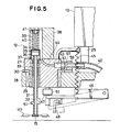
- a pivotable lever 55 about a pivot pin 54 has a pawl 56, which engages between the teeth of the gear 30 provided on the cylindrical body 27 to impede the rotation of the cylindrical body 27, integral with a joint 57 connected to said hose 42.
- Numeral 58 designates an engaging body, and a spring 59 is provided between the engaging body 58 and said lever 55 so that said sprint 59 is always biased to cause the pawl 56 to engage the gear 30.
- the end of the joint 57 is formed into a reduced diameter portion, offset portion of which is provided a stopper 60, and a seal packing 61 as a ring-like or cylindrical seal member is wound about the reduced diameter portion so that the end may abut with the stopper 60. Accordingly, where the pawl 56 is being engaged with the gear 30 by the spring 59, the joint 57 and the communication chamber 43 are communicated with each other so as not to produce a vacuum leak under the completely sealed condition by said packing 61.
- connection hose 62 which extends through the turntable 10 and is embedded, the connection hose 62 being communicated with a vacuum pump (not shown) through a switching valve 63, a laterally extending intake passage 64 and a central intake passage 65 of the cylindrical body 27.
- a valve stem 66 is slidably mounted on a bearing body 67, and a valve body 68 is mounted on the end of the valve stem 66.
- a spring 69 causes the valve body 68 to close an end opening of the latrally extending intake passage 64 of the turntable 10 to shut off the vacuum circuit formed by the vacuum pump.
- the valve stem 66 is bored with an atmosphere communication passage 70 through which the valve body does not extend, and the side of the communication passage 70 closer to the valve body 68 is bored with a lateral hole 71 so that a valve chamber 72 can be communicated with the atmosphere.
- valve chamber 72 is connected with the atmosphere through the lateral hole 71 and the communication passage 70, and when the valve body 68 opens the intake passage 64, the lateral hole 71 is closed by the baring body 67 to form a vacuum circuit.
- a collar 73 is mounted on the other end of the valve stem 66, and a first lever 75, one end of which is pivotally supported by a pin 74, has the other end in contact with the collar 73.
- An approximately ⁇ -shaped second lever 76 is pivotably supported at its intermediate portion by a pin 77, and rotatable rollers 78 and 79 are provided on opposite ends thereof. With this, when the second lever is swung by means of a drive source not shown, one roller 78 becomes engageable with a first recess 80 and a second recess 81 of the first lever 75 beyond a projection 82.
- the positioning device 19 will be described in detail.
- the aforesaid turntable 10 turns around working stations A to R, and the positioning stations D, E and F are provided with positioning devices 83, 84 and 85, respectively.
- the positioning device 83 is of the conventional construction and will be briefly explained.
- a belt 89 is extended between an output shaft pulley 87 of a drive motor 86 and a positioning unit 88, and a positioning pawl not shown may be rotated.
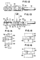
- the positioning devices 84 and 85 in the positioning stations E and F they will be described taking the device 84 as an example with reference to FIGS. 12 and 13.
- the positioning device 84 has two positioning units 90 and 91, and either units 90 and 91 may be moved to the position immediately under the suction nozzle 31 in the station E by a drive cylinder 92 in accordance with a program of a controller determined in advance according to the sizes of the tipped parts 15.
- the units 90 and 91 are provided movable with respect to a frame 93, and the frame 93 is linearly moved by contact of two pairs of guides 94 with a guide rail 95 from the side thereof.
- the units 90 and 91 are disposed with a spacing L1 left in the foremost end of the frame 93, and a belt 98 is extended between the units 90, 91 and an output shaft pulley 97 of a drive motor so that as the pulley 97 rotates, the units 90 and 91 are rotated in synchronism therewith.
- a line connecting centers of the units 90 and 91 is parallel with a moving direction of the frame 93 which moves along the guide rail 95.
- the moving amount of the frame 93 connected through a connection member 100 to a rod 99 of the drive cylinder 92 is defined by a backward-movement limiting stopper 101 secured to a fixed portion of the cylinder 92 and a forward-movement limiting stopper 102 so that said moving amount is the same distance of said spacing L1.
- a pusher 103 When a pusher 103 is moved upward by means of a cam (not shown), a first opening and closing plate 105 is rotated about a pin 104 in a direction of opening a positioning pawl 106, and therefore, a second opening and closing plate 107 is also rotataed about a pin 108 in response to the rotation of the first opening and closing plate 105 to open the pawl 109.
- a pusher 103 is moved downward, both the pawls 106 and 109 are closed by a spring 111 with one end thereof supported on a fixed portion 110 to hold the tipped part 115 suctioned by the suction nozzle 31 to position the part 15.
- the number of the positioning pawls are four per unit but the opening and closing of the other pair of pawls 112 and 113 are similarly constructed.
- Numeral 114 designates a stopper which is to limit the closing direction of the opening and closing plate 105.
- the positioning pawls 106, 109, 112 and 113 are rotated, during the rotation of the turntable 10, by the drive motor 96 in the direction in which the tipped part 15 suctioned by the suction nozzle 31 is rotated, that is, in the direction adjusted to the direction when the part 15 is mounted on the print substrate. Then, when the suction nozzle 31 is moved downward, the positioning for only the centering operation is carried out.
- most of the tipped parts 15 have a symmetrical shape, and therefore, where the tipped parts 15 are rotated through 180° and mounted on the print substrate, if the suction nozzle 31 is rotated as previously mentioned so that the tipped parts 15 are rotated in advance through 180°, the pawls 106, 109, 112 and 113 needs not be rotated during the rotation of the turntable 10.
- the construction of the positioning unit 90 is substantially similar to that of the unit 91 but positioning pawls 112A and 113A have a thickness greater than that of the pawls 112 and 113. Accordingly, the pawls 112A and 113A will not position the cylindrical-shaped tipped part 15A per se but the suction nozzle 31A is positioned, as a result of which the direction of the center axis of the part 15A is positioned. In positioning the suction nozzle 31A, a dimension L2 between planes 31C abnd 31D of the nozzle 31A is made longer than the diameter of the part 15A.
- the part 15A is not disengaged from a groove 31B and the tipped parts 15A are not displaced when both the pawls 112A and 113A.
- the construction for opening and closing the other pair of positioning pawls 106A and 109A is similar to that of the aforementioned positioning unit 91 but the positioning pawls 112A and 113A serves to position the suction nozzle 31A per se whilst the axial direction of the cylindrical tipped part 15A is directly positioned.
- the horizontal width of both the pawls 106A and 109A is formed to be shorter than the dimension L2 between the planes 31C and 31D of the suction nozzle 31A and slightly longer than the tipped part 15A.
- a circular portion of a portion buldged out of the groove 31B is held to thereby position the axial direction of the tipped part 15A.
- the parts are positioned by any of the positioning units 88, 90, 91, 115 and 116 in any of the stations.
- which unit is used is selected according to the program of the controller depending on the sizes and shapes of the tipped parts 15.
- the suction nozzle 13 will not be moved downward by a mechanism not shown and in addition, the non-selected positioning unit is not operated.
- FIG. 17 shows the displacement of the upper and lower levels of the suction nozzle 31.
- the working stations A, D, E, F and J for performing the works it is moved away from the cam 22 to effect upper and lower operations. This can be achieved by provision of upper and lower rails (not shown), which is associated with the cam 22 or moved down, at the portion in which the cam 22 is interrupted.
- the positioning units 88, 90, 91, 115 and 116 for positioning the tipped parts 15, photosensors 117 and 118 as the presence or absence detection means for detecting presence or absence of the parts 15, and a photosensor 119 as detection means capable of being swung by a drive motor 120 for detecting the suction attitude are located below the suction nozzles 31, and therefore the parts 15 have to be moved at a high level.
- the suction nozzle 31 has to be moved down immediately above the print substrate because the tipped parts 13 are mounted.
- FIG. 18 shows the state of the working stations H and I from the right-hand, in which the roller 24 at the upper end of the suction head 31, which has travelled on the cam 22 from the station H by rotation of the turntable 10 is moved onto the upper and lower rails 121 and carried to the next station I.
- the construction of the rail 121 will be described in detail with reference to FIGS. 19 and 20.
- the rail 121 is pivotable about a pin 122.
- the state wherein a stopper 121 biased by a spring 123 and projectingly provided on the rail 121 is in contact with a shaft 125 is the state at the upper portion in FIG. 19.
- the shaft 125 is moved upward and downward by a cam drive mechanism (not shown) to move the rail 121 upward and downward through the pin 122.
- a rotatable roller 126 is mounted on the end of the rail 121, and the roller 24 is moved away from the rail 121 by pushing down the roller 126 by a push-down member 127.
- a part thereof in which the rail 121 is disposed is interrupted, and one end side of said interrupted place is greatly different in upper and lower positional relation from the other end side thereof, because of which the rail 121 is disposed at the interrupted portion for vertical movement.
- the cam 22A on one end side positioned upwardly and the rail 121 are in the same level, and thereafter the roller 24 is moved onto the rail 121 and then the rail 121 moves down together with the shaft 125, as a consequence of which the rail 121 assumes the same level as that of the lower cam 22B.
- the roller 24 is then moved onto the lower cam 22B, the state of the station J.
- the rail 121 is rotated as shown in FIG. 20, after which the rail 121 is moved upward to assume the same level as the upper cam 22A and the push-down member 127 also moves above the roller 126. While in the present embodiment, an example has been shown in which the rail 121 is used for the transfer from up to down, it is to be noted that the rail 121 is not limited thereto but can be used for the transfer from down to up in the case where there is a difference in the upper and lower positional relation.
- the tipped parts 15 are urged by the pawls 106, 109, 112 and 113 from all directions to perform the positioning in the direction of axis X and in the directionof axis Y, and the positioning in the direction of ⁇ by the drive motor 96 through the belt 98, it is to be noted that the arrangement is not limited thereto but for example, the position of the tipped parts 15 can be optically detected to rotate the suction nozzle 31 to thereby decide the positions in the directions of axes X and Y and decide the position in the direction of ⁇ at the XY table 4.
- the print substrate is positioned by the positioning device not shown on the XY table 4 but the transfer device 3 causes the feed pawls 7 and 8 to be moved upward and returns to its original position along the rail 6.
- the XY table 4 is moved down as shown in FIG. 22 by the drive means (not shown) and becomes movable in the longitudinal direction (in the direction of axis Y) and in the lateral direction (in the direction of axis X) (see FIG. 23) whereby the XY table 4 moves to the lower position of the turntable 10 and the positioning device 19.
- the state is that the supply bed 13 has already been moved along the rail 14 so that among the plurality of tape supply units 18 juxtaposed on the part supply bed 13, a suitable one of the units 18 is in opposition to the turntable 10, and the upper film of the tape 16 wound about the reel 17 is peeled off by the peeling mechanism not shown and the tipped part is in a position directly under the suction nozzle 31.
- the index unit is rotated by the motor and the turntable 10 is intermittently rotated.
- the tipped part 15 is suctioned and chucked by the lower end of the suction nozzle 31 from the tape supply unit 18.
- the lower end of the suction nozzle 31 of the suction nozzle 12 must be lowered to a level of the tape 16. This may be accomplished in such a way that the roller 24 on the upper end of the head is placed on the vertially movable rail (not shown) disposed in the interruppted portion of the cam 22 of the cam member 20.
- This suctioning is carried out in such a way that the joint 57 in communication with the communication chamber 43, the hose 42, the connection hose 62, the valve chamber 72, the laterally extending intake passage 64, the central intake passage 65 of the cylindrical portion 21 and the vacuum pump (not shown) are connected through the suction nozzle 31 of the suction head 12, the filter 35, the accommodation chamber 40 of the cylindrical body 27, the communication passage 44, the communication chamber 43 and the seal packing 61 to form the vaccum circuit.
- the suction head 12 moved upward from the suction level is moved to the second working station B through the roller 24 slidably moving on the cam 22 of the cam member 20.
- this station B whether the suction nozzle 31 suctions the tipped part 15 is detected by the photosensor 117, and the suction nozzle 31 is rotated by the rotating device while suctioning the tipped part in the direction programmed in advance in the controller (not shown). More specifically, as shown in FIG. 6, the rotating roller 50 is pressed against the projection 51 of teh suction nozzle 31 from the outside, and the drive motor 52 is rotated to thereby rotate the rotating roller 50 by a fixed angle through the belt 53. After this rotation, the rotating roller 50 is moved away from the suction nozzle 31. In this manner, the tipped part 15 is rotated in advance prior to positioning so as to provide the direction when the tipped part 15 is mounted.
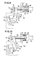
- the suction nozzle 31 does not suction the tipped part 15, the vacuum circuit to the suction head 12 is shut off by the switching valve 63. That is, when the roller 70 is urged by the drive source not shown so that the mode is changed from the FIG. 11 state to the FIG. 9 state, the second lever 76 swings, and the roller 78 having engaged the second recess 81 of the first lever 75 moves beyond the projection 82 into the engagement with the first recess 80. Accordingly, the first lever 75 is also rotated clockwise, and the valve stem 66 is moved by the spring 69 so that the valve body 68 closes the laterally extending intake passage 64. Thereby, the suction nozzle 31 comes into communication with the atmosphere through the hose 42, the connection hose 62, the valve chamber 72, the lateral hole 71 of the valve stem 86 and the atmosphere connection passage 70.
- the frame 93 is moved through the spacing L1 along the guide rail 95 through the rod 99 by the drive cylinder 92, the position is decided by the forward-movement limiting stopper 101, and the unit 91 has already been moved before the suction nozzle 31 arrives at the position directly below the nozzle 31.
- the stations D and F are idle stations.
- the positioning operation for the tipped parts 15 will be described hereinafter.
- the cam (not shown) is moved upward by the pusher 103, the first and second opening and closing plates 105 and 107 are rotated about the pins 104 and 108, respectively, against the spring 111, and the positioning pawls 106, 109, 112 and 113 open.
- the suction nozzle 31 is moved dow by downward movement of the rail (not shown) on which the roller 24 on the upper end of the suction head 12.
- the pusher 103 When the pusher 103 is moved down, they are held by the pawls 106, 109, 112 and 113 and positioned from all directions.
- the rail moves upward and the suction nozzle 31 also moves upward. Thereafter, the turntable is intermittently rotated through one division.
- the suction nozzle 31 suctions the tipped part 15 or whether the suction nozzle 31 suctions the tipped prt 15 in a normal position are detected by the photosensors 118 and 119.
- the sensor 119 can be swung by the drive motor 120 and checks the suction attitude of the tipped part 15.
- a single sensor can be used to detect the presence or absence and the attitude of a part.
- the suction nozzle 31 is rapidly moved down to the level Z, which will be described with reference to FIGS. 19 and 20.
- the upper cam 22A is the same level as the rail 121.
- the roller 24 is moved onto the rail 121 and then the rail 121 together with the shaft 125 are moved down to assume the same level as the lower cam 22B.
- the roller 126 is pushed down by the push-down member 127. Then, as shown in FIG.
- the rail 121 is rotated against the spring 123, and thereafter the rail 121 is moved upward together with the shaft 125 to assume the same level as the cam 22A, and the push-down member 127 is also moved so as to be moved upwardly of the roller 126.
- the tipped part 15 is mounted on the print substrate on the XY table 4. For this reason, the suction nozzle 31 is moved down to the substrate by the rail not shown for carrying out the mounting.
- the switching valve 63 is actuated as described above whereby the laterally extending the intake passage 64 is closed by the valve body 68, the valve chamber 72 is brought into communication with the atmosphere through the atmosphere communication passage 70 of the valve stem 66 and the high pressure air is blown through the end on the atmosphere side of the valve stem 66 to thereby perform mounting as previously described.
- the suction nozzle 31 will not be moved down to effect no mounting.
- the succeeding stations K, L and M are idle stations.
- the discharge station N even if the presence of the tipped part 15 is detected by the photosensors 117 and 118, but the abnormality of the suction attitude is judged by the photosensors 117 and 118, the tipped part 15 is discharged from the lower end of the suction nozzle 31. That is, as described above, the vacuum circuit is shut off and the high pressure air is blown through the end of the valve stem 66.
- the duct or the like drawn through the end of the suction nozzle 31 is interrupted by the filter 35 and stay within the space 36 of the filter case 37, the when the high pressure air is blown in in the aforementioned packaging station J and the discharge station N, the dust is discharged from the lower end of the nozzle 31 to automatically clean the filter 35 and its peripheral portion. Accordingly, when the vacuum circuit is formed, the dust or the like will not be stopped up in the circuit.
- next station 0 which nozzle 31 among the three suction nozzles 31 of the suction head 12 is used is detected by the sensor not shown.
- next nozzle selection station P which suction nozzles 31, 31, 31 is next used on the basis of the data programmed by the controller is selected.
- the same suction nozzle 31 can be used and the selection need not be carried out but they can be sequentially replaced.
- selection can be made so that suction nozzles corresponding thereto may be used.
- connection switching device 49 This selecting operation or the operation of the connection switching device 49 will be described.
- the lever 55 is rotated by the drive mechanism not shown, the joint 57 and the pawl 56 are moved away from the cylindrical body 27 and the gear 30, respectively, a gear not shown is meshed with the gear 30, and the cylindrical body 27 is rotated by said gear in the drive mechanism (not shown) through the bearing 29.
- This rotation is carried out in a way such that the keep lever 46 is downwardly rotated by the engaging member 48 to move downward all the suction nozzles 31, 31 and 31.
- the lever 55 is rotated so that the joint 57 is in communication with the communication chamber 43 corresponding to the selected suction nozzle 31 to bring the pawl 56 into engagement with the gear 30, thus providing a complete seal by the seal packing 61.
- the keep lever 46 is returned by the spring 45 so that the keep lever 46 comes into contact with the flange surface 47 of the suction nozzle 31, and the suction nozzle 31 moves upward.
- the next station Q is an idle station.
- the nozzle 31A is rotated by the rotating roller 50 of the rotating device in the direction in which the tipped parts 15A may be easily suctioned from the tape supply unit 18 in the first working station A. That is, the nozzle 31A is rotated so that the axial direction of the cylindrical tipped parts 15A supplied from the tape supply unit 18 is coincided with the direction of the groove 31B of the suction nozzle 31A.
- the suction nozzle 31A is not selected, and the suction nozzle 31 is used while not being replaced, such as operation is not carried out.
- the suction nozzle 31A suctions the cylindrical tipped part 15A from the tape supply unit 18 which accommodates therein said parts 15A.
- the suction nozzle 31A is rotated by the rotating device while suctioning the tipped part 15A in the direction programmed in advance in the controller (not shown). That is, the suction nozzle is rotated in advance prior to positioning so that the tipped part 15A assumes a direction used when mounting.
- the positioning operation for the tipped parts 15A will be described.
- the positioning pawls 106A, 109A, 112A and 113A are opened by the pusher 103 (the other not shown), the suction nozzle 31A moves down and the pusher 103 and the like moves down to close the pawls 106A, 109A, 112A and 113A.
- the planes 31C and 31D of the nozzle 31A are held by the pawls 112A and 113A to thereby determine the direction of an axis of the part 15A (see FIG. 24).
- the axial direction of the part 15A is directly positioned by the pawls 106A and 109A.
- the tipped part 15A can be urged by the pawls 112A and 113A, and therefore the part 15A is to be entered the groove 31B.
Landscapes
- Engineering & Computer Science (AREA)
- Manufacturing & Machinery (AREA)
- Microelectronics & Electronic Packaging (AREA)
- Supply And Installment Of Electrical Components (AREA)
- Automatic Assembly (AREA)
Applications Claiming Priority (2)
| Application Number | Priority Date | Filing Date | Title |
|---|---|---|---|
| JP62006553A JPH0767033B2 (ja) | 1987-01-14 | 1987-01-14 | 自動装着装置 |
| JP6553/87 | 1987-01-14 |
Publications (2)
| Publication Number | Publication Date |
|---|---|
| EP0275103A2 true EP0275103A2 (de) | 1988-07-20 |
| EP0275103A3 EP0275103A3 (de) | 1989-05-03 |
Family
ID=11641523
Family Applications (1)
| Application Number | Title | Priority Date | Filing Date |
|---|---|---|---|
| EP88100458A Withdrawn EP0275103A3 (de) | 1987-01-14 | 1988-01-14 | Vorrichtung zur automatischen Montage von Bauteilen |
Country Status (4)
| Country | Link |
|---|---|
| US (1) | US4905370A (de) |
| EP (1) | EP0275103A3 (de) |
| JP (1) | JPH0767033B2 (de) |
| KR (1) | KR900008670B1 (de) |
Families Citing this family (25)
| Publication number | Priority date | Publication date | Assignee | Title |
|---|---|---|---|---|
| JPH0828597B2 (ja) * | 1989-04-21 | 1996-03-21 | 三菱電機株式会社 | 電子部品実装装置 |
| JP2740348B2 (ja) * | 1989-10-17 | 1998-04-15 | 三洋電機株式会社 | テープ送出装置のカバーテープ剥離装置 |
| DE3935930A1 (de) * | 1989-10-27 | 1991-05-02 | Adalbert Fritsch | Bestueckungsgeraet |
| US5155903A (en) * | 1990-04-18 | 1992-10-20 | Matsushita Electric Industrial Co., Ltd. | Electrical component placing apparatus and placing method therefor |
| US5208975A (en) * | 1990-07-06 | 1993-05-11 | Matsushita Electric Industrial Co., Ltd. | Method and apparatus for mounting electronic parts |
| US5278634A (en) | 1991-02-22 | 1994-01-11 | Cyberoptics Corporation | High precision component alignment sensor system |
| US5217273A (en) * | 1992-05-14 | 1993-06-08 | H-Square Corporation | Serial pumping for portable handling tool of electronic workpieces |
| US5377405A (en) * | 1992-07-01 | 1995-01-03 | Yamaha Hatsudoki Kabushiki Kaisha | Method for mounting components and an apparatus therefor |
| JP3368923B2 (ja) * | 1992-12-28 | 2003-01-20 | 松下電器産業株式会社 | 電子部品実装装置 |
| KR100329586B1 (ko) * | 1993-10-29 | 2002-09-19 | 산요 덴키 가부시키가이샤 | 전자부품자동장착장치및전자부품의장착방법 |
| JP3313224B2 (ja) * | 1994-01-25 | 2002-08-12 | 松下電器産業株式会社 | 電子部品実装装置 |
| JP3282938B2 (ja) * | 1995-01-17 | 2002-05-20 | 松下電器産業株式会社 | 部品装着装置 |
| JP3554615B2 (ja) * | 1995-07-19 | 2004-08-18 | 株式会社日立ハイテクインスツルメンツ | 電子部品装着装置 |
| JP3549073B2 (ja) * | 1995-09-11 | 2004-08-04 | 松下電器産業株式会社 | 電子部品実装方法および電子部品実装装置 |
| JP3402988B2 (ja) * | 1997-01-31 | 2003-05-06 | 三洋電機株式会社 | 電子部品装着装置の上下動カム機構 |
| JP3768038B2 (ja) * | 1999-08-06 | 2006-04-19 | 株式会社日立ハイテクインスツルメンツ | 電子部品装着装置及び電子部品装着装置の装着ヘッド |
| KR100311747B1 (ko) * | 1999-08-20 | 2001-10-18 | 정문술 | 표면실장기의 인쇄회로기판 이송장치 |
| JP4037593B2 (ja) * | 1999-12-07 | 2008-01-23 | 松下電器産業株式会社 | 部品実装方法及びその装置 |
| JP4397509B2 (ja) * | 2000-05-01 | 2010-01-13 | 富士機械製造株式会社 | 電気部品保持ヘッド |
| WO2005011351A1 (en) * | 2003-07-30 | 2005-02-03 | Assembleon N.V. | Component placement device, nozzle exchange device as well as method for the exchange of nozzles |
| WO2007063763A1 (ja) * | 2005-11-29 | 2007-06-07 | Matsushita Electric Industrial Co., Ltd. | 回路基板に対する作業装置及び作業方法 |
| US7746481B2 (en) | 2007-03-20 | 2010-06-29 | Cyberoptics Corporation | Method for measuring center of rotation of a nozzle of a pick and place machine using a collimated laser beam |
| WO2008153885A1 (en) * | 2007-06-05 | 2008-12-18 | Cyberoptics Corporation | Component sensor for pick and place machine using improved shadow imaging |
| US20130269184A1 (en) * | 2012-04-12 | 2013-10-17 | Universal Instruments Corporation | Pick and place nozzle |
| JP7279567B2 (ja) * | 2019-07-30 | 2023-05-23 | 株式会社デンソーウェーブ | ロボット用吸着ハンド |
Family Cites Families (6)
| Publication number | Priority date | Publication date | Assignee | Title |
|---|---|---|---|---|
| US4503606A (en) * | 1980-12-26 | 1985-03-12 | Citizen Watch Company Limited | Automatic assembling machine |
| JPS58105199U (ja) * | 1982-01-12 | 1983-07-18 | 興亜電工株式会社 | 電子部品の吸着装置 |
| JP2537770B2 (ja) * | 1984-08-31 | 1996-09-25 | 松下電器産業株式会社 | 電子部品の装着方法 |
| WO1986004479A1 (fr) * | 1985-01-21 | 1986-07-31 | Fuji Machine Mfg. Co., Ltd. | Procede et appareil de detection de la position d'un outil et appareil electronique de montage d'un outil |
| JPS62114289A (ja) * | 1985-11-14 | 1987-05-26 | 松下電器産業株式会社 | 電子部品の装着方法および装置 |
| US4727647A (en) * | 1986-08-18 | 1988-03-01 | Universal Instruments Corporation | VCD tooling for DIP components of different widths |
-
1987
- 1987-01-14 JP JP62006553A patent/JPH0767033B2/ja not_active Expired - Lifetime
- 1987-12-31 KR KR1019870015618A patent/KR900008670B1/ko not_active Expired
-
1988
- 1988-01-12 US US07/144,060 patent/US4905370A/en not_active Expired - Fee Related
- 1988-01-14 EP EP88100458A patent/EP0275103A3/de not_active Withdrawn
Also Published As
| Publication number | Publication date |
|---|---|
| KR900008670B1 (ko) | 1990-11-26 |
| JPH0767033B2 (ja) | 1995-07-19 |
| US4905370A (en) | 1990-03-06 |
| JPS63174400A (ja) | 1988-07-18 |
| EP0275103A3 (de) | 1989-05-03 |
| KR880009545A (ko) | 1988-09-15 |
Similar Documents
| Publication | Publication Date | Title |
|---|---|---|
| EP0275103A2 (de) | Vorrichtung zur automatischen Montage von Bauteilen | |
| KR100502595B1 (ko) | 전자부품자동장착장치 | |
| EP1041870B1 (de) | Bestückungsmethode und Vorrichtung für elektrische Bauteile | |
| WO1985003404A1 (en) | Head for handling electrical components | |
| JP3398109B2 (ja) | 電子部品装着装置 | |
| JP2002057498A (ja) | 配線板作業システム | |
| JP3554615B2 (ja) | 電子部品装着装置 | |
| KR100273837B1 (ko) | 웨이퍼링의공급장치 | |
| JPH11151624A (ja) | ワーク供給装置 | |
| US4769904A (en) | Method and apparatus for handling leaded and leadless surface mountable components | |
| US6152283A (en) | Circuit-component supplying method and circuit-component feeder | |
| JP2589075B2 (ja) | 自動装着装置 | |
| JPH10209687A (ja) | 表面実装機のノズル昇降用エアシリンダの構造 | |
| JPS63174393A (ja) | 自動装着装置 | |
| JPH08130397A (ja) | 電子部品自動装着装置及び電子部品の装着方法 | |
| JPH11239929A (ja) | ブッシュ組付装置 | |
| EP0213746A2 (de) | Verfahren und Vorrichtung zur Handhabung von oberflächenmontierbaren Bauteilen, mit und ohne Drähte | |
| JPS61142798A (ja) | 電子部品装着装置 | |
| JPH01103900A (ja) | ロータリーヘッド型チッププレーサ | |
| JP2001210997A (ja) | 電子部品装着装置 | |
| JPH0812957B2 (ja) | 自動装着装置 | |
| JPH0767031B2 (ja) | 自動装着装置 | |
| JP2006128482A (ja) | 電子部品装着装置の装着ヘッド | |
| JPS63174399A (ja) | 自動装着装置 | |
| JPH0693558B2 (ja) | 電子部品装着装置 |
Legal Events
| Date | Code | Title | Description |
|---|---|---|---|
| PUAI | Public reference made under article 153(3) epc to a published international application that has entered the european phase |
Free format text: ORIGINAL CODE: 0009012 |
|
| AK | Designated contracting states |
Kind code of ref document: A2 Designated state(s): AT BE CH DE ES FR GB GR IT LI LU NL SE |
|
| RBV | Designated contracting states (corrected) |
Designated state(s): DE FR GB IT SE |
|
| PUAL | Search report despatched |
Free format text: ORIGINAL CODE: 0009013 |
|
| AK | Designated contracting states |
Kind code of ref document: A3 Designated state(s): DE FR GB IT SE |
|
| 17P | Request for examination filed |
Effective date: 19891030 |
|
| 17Q | First examination report despatched |
Effective date: 19910909 |
|
| STAA | Information on the status of an ep patent application or granted ep patent |
Free format text: STATUS: THE APPLICATION IS DEEMED TO BE WITHDRAWN |
|
| 18D | Application deemed to be withdrawn |
Effective date: 19921217 |