EP0275105B1 - Adaptateur pour tubes respiratoires - Google Patents
Adaptateur pour tubes respiratoires Download PDFInfo
- Publication number
- EP0275105B1 EP0275105B1 EP88100468A EP88100468A EP0275105B1 EP 0275105 B1 EP0275105 B1 EP 0275105B1 EP 88100468 A EP88100468 A EP 88100468A EP 88100468 A EP88100468 A EP 88100468A EP 0275105 B1 EP0275105 B1 EP 0275105B1
- Authority
- EP
- European Patent Office
- Prior art keywords
- adapter
- tubular body
- interior
- wall
- slits
- Prior art date
- Legal status (The legal status is an assumption and is not a legal conclusion. Google has not performed a legal analysis and makes no representation as to the accuracy of the status listed.)
- Expired - Lifetime
Links
- 238000004891 communication Methods 0.000 claims description 4
- 239000012530 fluid Substances 0.000 claims description 4
- 230000007423 decrease Effects 0.000 claims 1
- 239000007789 gas Substances 0.000 description 27
- 238000005070 sampling Methods 0.000 description 12
- 239000000463 material Substances 0.000 description 4
- 230000028327 secretion Effects 0.000 description 4
- 238000012544 monitoring process Methods 0.000 description 3
- 229920003023 plastic Polymers 0.000 description 3
- 239000004033 plastic Substances 0.000 description 3
- 230000029058 respiratory gaseous exchange Effects 0.000 description 3
- 239000007787 solid Substances 0.000 description 3
- CURLTUGMZLYLDI-UHFFFAOYSA-N Carbon dioxide Chemical compound O=C=O CURLTUGMZLYLDI-UHFFFAOYSA-N 0.000 description 2
- 206010036790 Productive cough Diseases 0.000 description 2
- 230000000903 blocking effect Effects 0.000 description 2
- 230000008878 coupling Effects 0.000 description 2
- 238000010168 coupling process Methods 0.000 description 2
- 238000005859 coupling reaction Methods 0.000 description 2
- 230000002209 hydrophobic effect Effects 0.000 description 2
- 238000000034 method Methods 0.000 description 2
- 210000003802 sputum Anatomy 0.000 description 2
- 208000024794 sputum Diseases 0.000 description 2
- 238000009423 ventilation Methods 0.000 description 2
- 238000003466 welding Methods 0.000 description 2
- 238000012935 Averaging Methods 0.000 description 1
- 238000004026 adhesive bonding Methods 0.000 description 1
- 229910002092 carbon dioxide Inorganic materials 0.000 description 1
- 239000001569 carbon dioxide Substances 0.000 description 1
- 230000006835 compression Effects 0.000 description 1
- 238000007906 compression Methods 0.000 description 1
- 238000011109 contamination Methods 0.000 description 1
- 238000010586 diagram Methods 0.000 description 1
- 238000001914 filtration Methods 0.000 description 1
- 239000000499 gel Substances 0.000 description 1
- 239000003292 glue Substances 0.000 description 1
- 239000007788 liquid Substances 0.000 description 1
- 238000012806 monitoring device Methods 0.000 description 1
- 210000003097 mucus Anatomy 0.000 description 1
- 239000013618 particulate matter Substances 0.000 description 1
- 230000002685 pulmonary effect Effects 0.000 description 1
- 230000000241 respiratory effect Effects 0.000 description 1
- 230000008719 thickening Effects 0.000 description 1
- 230000009974 thixotropic effect Effects 0.000 description 1
- XLYOFNOQVPJJNP-UHFFFAOYSA-N water Substances O XLYOFNOQVPJJNP-UHFFFAOYSA-N 0.000 description 1
Images

Classifications
-
- A—HUMAN NECESSITIES
- A61—MEDICAL OR VETERINARY SCIENCE; HYGIENE
- A61B—DIAGNOSIS; SURGERY; IDENTIFICATION
- A61B5/00—Measuring for diagnostic purposes; Identification of persons
- A61B5/08—Measuring devices for evaluating the respiratory organs
- A61B5/097—Devices for facilitating collection of breath or for directing breath into or through measuring devices
-
- A—HUMAN NECESSITIES
- A61—MEDICAL OR VETERINARY SCIENCE; HYGIENE
- A61M—DEVICES FOR INTRODUCING MEDIA INTO, OR ONTO, THE BODY; DEVICES FOR TRANSDUCING BODY MEDIA OR FOR TAKING MEDIA FROM THE BODY; DEVICES FOR PRODUCING OR ENDING SLEEP OR STUPOR
- A61M16/00—Devices for influencing the respiratory system of patients by gas treatment, e.g. ventilators; Tracheal tubes
- A61M16/08—Bellows; Connecting tubes ; Water traps; Patient circuits
-
- A—HUMAN NECESSITIES
- A61—MEDICAL OR VETERINARY SCIENCE; HYGIENE
- A61M—DEVICES FOR INTRODUCING MEDIA INTO, OR ONTO, THE BODY; DEVICES FOR TRANSDUCING BODY MEDIA OR FOR TAKING MEDIA FROM THE BODY; DEVICES FOR PRODUCING OR ENDING SLEEP OR STUPOR
- A61M16/00—Devices for influencing the respiratory system of patients by gas treatment, e.g. ventilators; Tracheal tubes
- A61M16/08—Bellows; Connecting tubes ; Water traps; Patient circuits
- A61M16/0816—Joints or connectors
- A61M16/0841—Joints or connectors for sampling
- A61M16/085—Gas sampling
Definitions
- the present invention relates to an airway adapter of the type as outlined in the preamble of claim 1.
- Some patients receiving automatic ventilation through an artificial air tube are monitored for respiratory problems by drawing a small sample flow of gas from the air tube and continuously analyzing the level of carbon dioxide (capnography) or other gases.
- a sampling tube is connected to the air tube for conveying a sampled flow of gas from the air tube to the gas monitoring equipment, the diameter of the sampling tube being small compared to the diameter of the air tube.
- Ventilated patients in the Intensive Care Unit commonly have pulmonary problems with many secretions such as copious mucous sputum.
- These secretions are thixotropic gels which can and do solidify and adhere to a variety of surfaces, including the plastics used in medical tubing and related connectors and adapters used in gas monitoring devices.
- a vacuum is applied to one end of the sampling tube using, for example, a pump in the gas monitoring equipment. This can cause the above mentioned secretions to enter the gas sampling tube and gas monitoring equipment causing inaccurate measurement, or the entrance into the sampling tube can become blocked causing the sample gas flow to stop or become unacceptably low.
- the known adapter uses a hydrophobic baffle as a filtering material over the sample port hole of airway adapters, but this slows down the sampling process relative to the respiration cycle of the patient.
- the adapter in one embodiment comprises two tubular members which, when attached to each other, enclose and secure in place a sleeve of the hydrophobic baffle material.
- the channel and the port for providing fluid communications between the channel and a sampling air tube are formed into a flange portion of one of the two tubular members.
- the flange portion has an inner diameter to snugly fit the outer diameter of the other tube member.
- US-A-3 777 571 describes an air-collecting vessel using a two-chambered bag to collect average exhaled gases from a patient.
- the exhaled gases pass into an inner chamber and migrate through a series of slot-shaped openings to the outer chamber where gases sampled through an extension tube with a series of holes along its length.
- the inner chamber has an inner diameter which is significantly greater than the inner diameters of the tubes attached to the chamber.
- the chamber neither contains conical surfaces nor a protruding region.
- this reference is directed towards a method of averaging exhaled gases in order to provide a more uniform sample, but does not address the problem of blocking the passage of sputum, mucus, and water.
- Another object of the present invention is to provide for quicker sampling of the gas stream relative to the respiration cycle of the patient.
- An airway adapter fulfilling the above defined needs comprises the features of claim 1.
- the walls of the tubular body gradually increase from either side of the annular channel toward the annular channel. This creates an interior conical surface which narrows from on either side of the annular channel up to the region where the annular channel is located.
- FIG. 1 is a greatly enlarged, elevational, cross sectional view of a preferred embodiment airway tube adapter designated generally 100 taken along the longitudinal axis 101 in FIG. 2.
- the airway tube adapter 100 comprises three parts: a first tubular portion 102, a second tubular portion 104 and a sample tube connector 106.
- the first tubular portion 102 comprise a cylindrical body portion 110 having a first constant outer diameter along its entire length and integrally formed with a shoulder portion 112.
- the cylindrical wall of the first tubular portion tapers in thickness to create a conically shaped interior surface 115 with a larger diameter at its open end 114 opposite the shoulder portion 112 and a smaller diameter at the shoulder portion open end.
- the shoulder portion 112 presents an annular end surface 116 in a plane substantially perpendicular to the longitudinal axis 101 of the first tubular portion.
- the first tubular portion 102 further comprises an annular groove 122 in the annular end surface 116.
- the annular end surface 116 is perpendicular to the longitudinal axis 101.
- a plurality of equally spaced radially extending slots 124 are located in the annular end surface 116 which slots open up into the conical interior 115 and extend therefrom to the annular groove 122.
- the annular end surface 116 further comprises a semi-cylindrical cut-out 126 and an adjoining coaxial, smaller diameter semi-cylindrical cut out 128 each having a common axis perpendicular to the longitudinal axis 101 of the airway tube adapter 100.
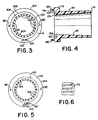
- FIG. 4 is an elevational cross section of the first tubular portion which cuts through diametrically opposite slots 124 taken along a diameter 90° from a diameter lying along the axis of the cut outs 126 and 128.
- FIG. 3 is an end view of the first tubular portion 102 viewed from the shoulder end 112.
- the outside diameter of the shoulder is 14,3 mm (0.750 inches) (circle 302) while the internal diameter of the interior conical surface (circle 304) is 10,2 mm (0.400 inches).
- FIG. 3 shows the slots 124 extending from the interior surface to the annular groove 122 which has a 12 mm (0.472 inch) diameter as measured by its centerline and a groove width of 0,8 mm (0.032 inches).
- Circle 306 shows the smaller diameter of the groove of which circle 308 is the larger diameter.
- Cut out 126 has a diameter of 6 mm (0.237 inches) while cut out 128 has a 1,6 mm (0.062 inch) diameter.
- the second tubular portion 104 is cylindrically shaped having a first constant outer diameter from one open end 136 to the opposite end.
- the interior surface has a constant diameter at surface 142 for a predetermined distance from end 136 whereupon it tapers in conical fashion 145 to a diameter at its opposite end which diameter equals or is substantially the same as the diameter of the interior conical surface of the first tubular portion 102 at the annular surface 116 formed by shoulder 112.
- the outer diameter of the second tubular portion 104 equals or is substantially the same as the outer diameter of the shoulder 112. As seen in FIG.
- annular surface 150 of the second tubular portion 104 looks much like the annular surface 116 and includes an annular groove 152 of the same diameter and width as annular groove 122 in the end surface 116 of the first tubular portion.
- Annular surface 150 further includes a plurality equally spaced radially extending slots 154 which extend from and open up into the interior conical surface to the annular groove 152. There are, in the preferred embodiment, the same number of slots in the second tubular portion as in the first.
- Annular surface 150 comprises a first larger diameter cut out 160 adjoining a second, coaxial smaller diameter cut out 162 which together extend from the circumferential surface 164 of the second tubular portion to the annular groove 152.
- annular channel 170 in the airway adapter which is spaced apart from the hollow interior of the adapter and the slots come together to form a a plurality of radial channels 172 allowing the interior of the hollow adapter to communicate with the annular channel 170.
- FIG. 6 is an enlarged detail of the radial channels 172 formed by the slots 124.
- Each channel is 0,051 mm (0.002 inches) high and 1,27 mm (0.050 inches) wide and there are, in the preferred embodiment, 36 of them equally spaced about at least a portion of the circumference.
- tubular portions 102 and 104 are made of a clear plastic and are joined together by gluing or sonic welding, for example.
- annular end surface 116 has two diametrically opposite pins 180 integrally formed with the first tubular portion 102 and extending perpendicularly away from surface 116.
- the pins are located between the annular groove 122 in the end surface and the outer periphery 302.
- Annular end surface 150 comprises two diametrically opposite holes 182 adapted to receive the pins 180 and in so doing align the opposing end surface 116 and 150.
- the holes are 1,6 mm (0.063 inches) in diameter and 2,4 mm (0.095 inches) deep.
- the sampling tube fitting 106 is also clear plastic and cylindrical in shape having a diameter just under the diameter of the cylindrical cavity 170. The diameters are such that when the fitting 106 is inserted into the cylindrical cavity 170 it forms a tight frictional fit. Glue or ultrasonic welding may also be used to provide a more secure bond between the fitting and the cavity.
- the conical taper of the interior of the first tubular portion is 4° with a center line length of 19,1 mm (0.753 inches), while the taper of the second tubular portion is 8° with a centerline length of 24,8 mm (0.976 inches).
- the hollow interior of the adapter gradually narrows as gas flowing through the adapter passes from one end toward the junction of the two portions, and then the interior widens again as the gas flows towards the opposite end.
- the cross section of the interior is at its narrowest because the gradually thickening walls of the two tubular portions are thickest there.
- the radial channels form slits through the junction region 190 where they open up into the interior.
- the slits are parallel with the longitudinal axis 101 of the adapter.
- the junction region may come to a peak, as in the preferred embodiment, but might also take on a convex shape if desired.
- the cylindrical body portion 110 of the first tubular portion is adapted to fit within an airway tube 402 coupled to a respirator or automatic ventilator 404 while an endotracheal tube 406 coupled to the patient 408 fits within the cylindrical body of the second tubular portion at 142.
- a sampling air tube 410 is coupled to the connector 106 and is connected at its other end to a vacuum source 412.
- the patient's exhalations or gas flow pass through the airway adapter generally along its longitudinal axis 101.
- the gas flow is channeled along the interior conical surface from the endotracheal tube picking up velocity as the adapter interior narrows.
- the gas flow passes the junction region 190 through the slits formed therein by the radial channels 172, the gas has been compressed and expands into the radial channels 172.
- the slits insure good coupling between the radial channels and the gas flow.
- the sampled gas flow is pulled through the radial channels 172, into and around the annular channel 170, and then through the cylindrical cavity 176, connector 106 and the sampling tube 410 connected to the connector 106. Because the radial channel cross sections are so small the liklihood that mucous or other solid or semi-solid matter will enter the sample tube is greatly reduced. Because there are a plurality of slots which surround the periphery of the adapter interior the liklihood that all sample gas flow will be stopped because of blockage is also greatly reduced.
- the adapter of the present invention provides good coupling to the gas flow, with minimal disturbance to the flow and reduced chance of significant blockage or contamination of the sample gas flow.
Landscapes
- Health & Medical Sciences (AREA)
- Life Sciences & Earth Sciences (AREA)
- General Health & Medical Sciences (AREA)
- Engineering & Computer Science (AREA)
- Biomedical Technology (AREA)
- Heart & Thoracic Surgery (AREA)
- Pulmonology (AREA)
- Animal Behavior & Ethology (AREA)
- Public Health (AREA)
- Veterinary Medicine (AREA)
- Anesthesiology (AREA)
- Hematology (AREA)
- Emergency Medicine (AREA)
- Physiology (AREA)
- Physics & Mathematics (AREA)
- Biophysics (AREA)
- Pathology (AREA)
- Medical Informatics (AREA)
- Molecular Biology (AREA)
- Surgery (AREA)
- Investigating Or Analysing Biological Materials (AREA)
- Measurement Of The Respiration, Hearing Ability, Form, And Blood Characteristics Of Living Organisms (AREA)
- Sampling And Sample Adjustment (AREA)
Claims (7)
- Adaptateur (100) pour voies respiratoires pour l'obtention d'un échantillon d'écoulement de gaz à partir des exhalations d'un patient, comportant un corps tubulaire (102, 104) ayant un intérieur creux pour le passage d'un écoulement de gaz à travers lui, ledit corps tubulaire (102, 104) ayant une paroi (110) contenant un canal (170) dans ladite paroi (110) et un orifice (174, 176) dans ladite paroi (110) établissant une communication de fluide entre ledit canal (170) et l'atmosphère ambiante ; une zone en saillie (190) dans ledit intérieur creux, formée par des première et seconde surfaces intérieures coniques (145, 115) ; et des moyens (172) pour établir une communication de fluide entre l'intérieur dudit corps tubulaire (102, 104) et ledit canal (170), agencés à la zone en saillie (190), caractérisé en ce que
l'épaisseur d'au moins une partie de la paroi (110) dudit adaptateur (100) augmente progressivement dans la direction d'écoulement de gaz depuis une première extrémité (136) dudit corps tubulaire (102, 104) jusqu'au canal annulaire (170) pour former la première surface intérieure conique (145), l'épaisseur d'au moins une partie de la paroi (110) dudit adaptateur diminue progressivement dans la direction d'écoulement de gaz depuis ledit canal annulaire (170) jusqu'à l'autre extrémité (114) dudit corps tubulaire (102, 104) pour former la zone en saillie (190) de ladite paroi (110) dans ledit intérieur creux dans la zone dudit canal annulaire (170) ; et lesdits moyens comprennent plusieurs canaux radiaux (172) formant plusieurs fentes parallèles à travers ladite zone en saillie (190), lesdites fentes étant sensiblement parallèles à l'axe longitudinal (101) dudit adaptateur (100). - Adaptateur selon la revendication 1, comportant en outre un raccord cylindrique (106) conçu pour s'ajuster avec ledit orifice (174, 176) et faisant saillie à l'écart dudit adaptateur (100).
- Adaptateur selon l'une des revendications 1 ou 2, dans lequel la hauteur de chacun desdits panneaux radiaux (172), mesurée le long de la circonférence de l'intérieur de l'adaptateur, est sensiblement égale ou inférieure à 0,002 inch (0,051 millimètre).
- Adaptateur selon la revendication 3, dans lequel la longueur de chacune desdites fentes est sensiblement égale ou inférieure à 0,050 inch (1,27 millimètre).
- Adaptateur selon l'une quelconque des revendications 1 à 4, dans lequel ledit corps tubulaire comprend un axe longitudinal (101) et des première et seconde parties tubulaires (102, 104), lesdites première et seconde parties tubulaires ayant chacune une surface extrême (116, 150) dans un plan sensiblement perpendiculaire à l'axe (101), des gorges annulaires (122, 152) et des fentes (124, 154), s'étendant radialement, étant formées dans chacune desdites surfaces extrêmes (116, 150), lesdites gorges (122, 152) sont conçues pour former ledit canal annulaire (170) et lesdites fentes (124, 154) sont conçues pour former lesdits canaux radiaux (172) lorsque lesdites surfaces extrêmes (116, 150) desdites première et seconde parties tubulaires (102, 104) sont jointes entre elles pour former ledit corps tubulaire.
- Adaptateur selon l'une quelconque des revendications 1 à 5, dans lequel ladite zone en saillie (190) forme une crête.
- Adaptateur selon l'une quelconque des revendications 1 à 5, dans lequel ladite zone (190) en saillie a une forme convexe.
Applications Claiming Priority (2)
| Application Number | Priority Date | Filing Date | Title |
|---|---|---|---|
| US4359 | 1987-01-16 | ||
| US07/004,359 US4852583A (en) | 1987-01-16 | 1987-01-16 | Airway adapter |
Publications (3)
| Publication Number | Publication Date |
|---|---|
| EP0275105A2 EP0275105A2 (fr) | 1988-07-20 |
| EP0275105A3 EP0275105A3 (en) | 1989-11-08 |
| EP0275105B1 true EP0275105B1 (fr) | 1993-12-22 |
Family
ID=21710397
Family Applications (1)
| Application Number | Title | Priority Date | Filing Date |
|---|---|---|---|
| EP88100468A Expired - Lifetime EP0275105B1 (fr) | 1987-01-16 | 1988-01-14 | Adaptateur pour tubes respiratoires |
Country Status (6)
| Country | Link |
|---|---|
| US (1) | US4852583A (fr) |
| EP (1) | EP0275105B1 (fr) |
| JP (1) | JPS63240875A (fr) |
| AU (1) | AU1003288A (fr) |
| CA (1) | CA1300659C (fr) |
| DE (1) | DE3886427T2 (fr) |
Cited By (1)
| Publication number | Priority date | Publication date | Assignee | Title |
|---|---|---|---|---|
| US9498150B2 (en) | 2005-08-16 | 2016-11-22 | Oridion Medical 1987 Ltd. | Breath sampling device |
Families Citing this family (36)
| Publication number | Priority date | Publication date | Assignee | Title |
|---|---|---|---|---|
| US4953547A (en) * | 1989-01-26 | 1990-09-04 | Poole Jr Samuel E | Drug administering endotracheal respiration systems |
| US5181508A (en) * | 1989-01-26 | 1993-01-26 | Poole Jr Samuel E | Molded connector |
| US4938210A (en) * | 1989-04-25 | 1990-07-03 | Trudell Medical | Inhalation chamber in ventilator circuit |
| US4991591A (en) * | 1989-06-22 | 1991-02-12 | Jones William C | Spirometer with multi-stage fixed orifice |
| WO1991001771A1 (fr) * | 1989-08-04 | 1991-02-21 | Nellcor Incorporated | Adaptateur de voie d'air avec systeme de purge |
| DK0502910T3 (da) * | 1989-12-01 | 1996-06-10 | Borody Thomas J | Oralmedicinsk indretning til oxygenering |
| USD335343S (en) | 1990-08-22 | 1993-05-04 | Jones William C | Mouthpiece for a spirometer |
| US5063938A (en) * | 1990-11-01 | 1991-11-12 | Beck Donald C | Respiration-signalling device |
| US5282473A (en) * | 1992-11-10 | 1994-02-01 | Critikon, Inc. | Sidestream infrared gas analyzer requiring small sample volumes |
| US5467776A (en) * | 1993-07-28 | 1995-11-21 | The Brewer Company | Air sampling device and method for sampling exhaled air |
| US5465728A (en) * | 1994-01-11 | 1995-11-14 | Phillips; Michael | Breath collection |
| US5413095A (en) * | 1994-04-15 | 1995-05-09 | Arrow Precision Products, Inc. | Mouthpiece with oxygen receiving and directing structure |
| IL111162A (en) * | 1994-10-04 | 1998-01-04 | Irad Technologies Ltd | Filtering device utilizable with gas monitors |
| US5743270A (en) * | 1996-06-21 | 1998-04-28 | Desert Moon Development Limited Partnership | Resistive element for spirometer |
| IL119131A (en) | 1996-08-26 | 2002-04-21 | Oridion Medical Ltd | Multiple channel sample port for airway adaptor |
| US5932877A (en) * | 1997-04-17 | 1999-08-03 | Square One Technology, Inc. | High performance side stream infrared gas analyzer |
| US5925831A (en) * | 1997-10-18 | 1999-07-20 | Cardiopulmonary Technologies, Inc. | Respiratory air flow sensor |
| FR2770137B1 (fr) * | 1997-10-27 | 2000-01-28 | Georges Boussignac | Dispositif d'assistance respiratoire |
| USD413825S (en) * | 1998-09-14 | 1999-09-14 | Cardiopulmonary Technologies, Inc. | Respiratory air flow measuring device |
| US6468477B1 (en) | 2000-02-04 | 2002-10-22 | Hamilton Enterprises | Sealable air sampling bag |
| US20030024331A1 (en) * | 2000-02-04 | 2003-02-06 | Hamilton Enterprises, Inc. | Sealable air sampling bag and method of sealing an air sampling bag |
| FR2831824B1 (fr) * | 2001-11-06 | 2004-01-23 | Georges Boussignac | Dispositif pour assistance respiratoire |
| US20040089305A1 (en) * | 2002-11-13 | 2004-05-13 | Vallarta John-Eric S. | Endotracheal tube safety device connector |
| US7878980B2 (en) * | 2003-06-13 | 2011-02-01 | Treymed, Inc. | Gas flow diverter for respiratory monitoring device |
| GB0326403D0 (en) * | 2003-11-13 | 2003-12-17 | Vandagraph Ltd | Adaptor means |
| US20060058696A1 (en) * | 2004-09-10 | 2006-03-16 | Quintron Instrument Company | Air sampling apparatus with related sensing and analysis mechanism |
| US20060191536A1 (en) * | 2005-02-25 | 2006-08-31 | Allied Healthcare Products, Inc. | Bag mask resuscitator |
| USD556908S1 (en) | 2007-01-03 | 2007-12-04 | Jones Medical Instrument Company | Mouthpiece for a spirometer |
| US9011348B2 (en) * | 2008-06-23 | 2015-04-21 | Quintron Instrument Company, Inc. | Air sampling apparatus and methods |
| US20120226183A1 (en) | 2010-08-30 | 2012-09-06 | Quintron Instrument Company | Evacuated air chamber |
| US9055889B2 (en) | 2012-03-20 | 2015-06-16 | Commonwealth Laboratories, Inc. | Method and apparatus for breath testing |
| USD722688S1 (en) | 2013-07-17 | 2015-02-17 | Quintron Instrument Company, Inc. | Mouthpiece for breath testing |
| US10413216B2 (en) | 2016-02-03 | 2019-09-17 | Quintron Instrument Company, Inc. | Breath testing apparatus |
| DE102017008008A1 (de) * | 2017-08-25 | 2019-02-28 | Dräger Safety AG & Co. KGaA | Atemalkoholmessung mit berührungsloser Probenabgabe |
| EP3936044B1 (fr) | 2020-07-06 | 2024-12-18 | Dräger Safety AG & Co. KGaA | Collecteur d'échantillons pour recevoir un échantillon de gaz respiratoire et un dispositif de test d'échantillon de gaz |
| US12521506B2 (en) | 2021-05-26 | 2026-01-13 | Masimo Corporation | Low deadspace airway adapter |
Family Cites Families (9)
| Publication number | Priority date | Publication date | Assignee | Title |
|---|---|---|---|---|
| GB1113484A (en) * | 1965-10-29 | 1968-05-15 | William Warne & Company Ltd | Improvements in or relating to surgical tubes |
| DE7113512U (de) * | 1971-04-07 | 1971-07-29 | E Jaeger | Expirationsluft Sammeigefaß |
| US3667475A (en) * | 1971-05-10 | 1972-06-06 | Nat Equipment Research Inc | Endo-tracheal tube adaptors for use in administering gases |
| US3874377A (en) * | 1974-06-06 | 1975-04-01 | Kenneth L Davidson | Apparatus for endotracheal and esophageal intubation |
| GB2034468B (en) * | 1978-11-03 | 1983-02-09 | Jones T | Gas sampling devices |
| US4463755A (en) * | 1981-05-18 | 1984-08-07 | Terumo Corporation | Breathing circuit |
| US4558709A (en) * | 1982-10-30 | 1985-12-17 | Tokyo Shibaura Denki Kabushiki Kaisha | Gas introducing apparatus for respiratory gas analyzer |
| US4558708A (en) * | 1984-10-24 | 1985-12-17 | Tri-Med, Inc. | Patient's airway adapter to withdraw a patient's gas samples for testing free of sputum mucus and/or condensed water, by utilizing a hollow cylindrical hydrophobic liquid baffle |
| IL76939A (en) * | 1984-11-13 | 1990-01-18 | Andros Analyzers Inc | Adaptor assembly for airway tube |
-
1987
- 1987-01-16 US US07/004,359 patent/US4852583A/en not_active Expired - Fee Related
- 1987-12-22 CA CA000555109A patent/CA1300659C/fr not_active Expired - Fee Related
-
1988
- 1988-01-04 AU AU10032/88A patent/AU1003288A/en not_active Abandoned
- 1988-01-13 JP JP63005681A patent/JPS63240875A/ja active Pending
- 1988-01-14 DE DE88100468T patent/DE3886427T2/de not_active Expired - Fee Related
- 1988-01-14 EP EP88100468A patent/EP0275105B1/fr not_active Expired - Lifetime
Cited By (1)
| Publication number | Priority date | Publication date | Assignee | Title |
|---|---|---|---|---|
| US9498150B2 (en) | 2005-08-16 | 2016-11-22 | Oridion Medical 1987 Ltd. | Breath sampling device |
Also Published As
| Publication number | Publication date |
|---|---|
| DE3886427T2 (de) | 1994-04-14 |
| CA1300659C (fr) | 1992-05-12 |
| JPS63240875A (ja) | 1988-10-06 |
| EP0275105A2 (fr) | 1988-07-20 |
| US4852583A (en) | 1989-08-01 |
| AU1003288A (en) | 1988-07-28 |
| DE3886427D1 (de) | 1994-02-03 |
| EP0275105A3 (en) | 1989-11-08 |
Similar Documents
| Publication | Publication Date | Title |
|---|---|---|
| EP0275105B1 (fr) | Adaptateur pour tubes respiratoires | |
| US7980246B2 (en) | Low deadspace airway adapter | |
| EP0466334B1 (fr) | Adapteur pour tubes respiratoires à utilisation avec un système fermé de cathéter d'aspiration | |
| US4261355A (en) | Constant positive pressure breathing apparatus | |
| US4723543A (en) | Endotracheal tube connector | |
| US8240187B2 (en) | Breath sampling device and method for using same | |
| US4558708A (en) | Patient's airway adapter to withdraw a patient's gas samples for testing free of sputum mucus and/or condensed water, by utilizing a hollow cylindrical hydrophobic liquid baffle | |
| EP0707827B1 (fr) | Installation de filtration de fluides utilisable avec des analyseurs de gaz | |
| JP5208935B2 (ja) | モジュラー・サイドストリーム・ガス・サンプリング・アセンブリ | |
| CN1182888C (zh) | 呼吸救助装置 | |
| US4612929A (en) | Attachment for the supply of breathing gas for high-frequency artificial respiration | |
| US10926052B2 (en) | Airway tube | |
| US4677987A (en) | Gas sampling apparatus for capnography | |
| EP0201565B1 (fr) | Ensemble adapteur pour tube respiratoire | |
| US5520167A (en) | Nebulizer mask adaptor ring | |
| CA1183059A (fr) | Injecteur-humidificateur pour ventilateur a jet | |
| WO1991001771A1 (fr) | Adaptateur de voie d'air avec systeme de purge | |
| AU2003284020A1 (en) | Integrated sample cell and filter and system using same | |
| US7549316B2 (en) | Integrated sample cell and filter and system using same | |
| EP0161003A2 (fr) | Embouchure pour appareil d'essai de la fonction pulmonaire | |
| US20150297856A1 (en) | Airway device with integrated breath sampling | |
| EP3871724A1 (fr) | Raccord de sortie pour un dispositif de thérapie expiratoire positive | |
| WO2025233936A1 (fr) | Filtre de capnographie | |
| GB2414682A (en) | Guide for ancillary device |
Legal Events
| Date | Code | Title | Description |
|---|---|---|---|
| PUAI | Public reference made under article 153(3) epc to a published international application that has entered the european phase |
Free format text: ORIGINAL CODE: 0009012 |
|
| AK | Designated contracting states |
Kind code of ref document: A2 Designated state(s): CH DE FR GB IT LI |
|
| PUAL | Search report despatched |
Free format text: ORIGINAL CODE: 0009013 |
|
| AK | Designated contracting states |
Kind code of ref document: A3 Designated state(s): CH DE FR GB IT LI |
|
| 17P | Request for examination filed |
Effective date: 19900329 |
|
| 17Q | First examination report despatched |
Effective date: 19910516 |
|
| RAP1 | Party data changed (applicant data changed or rights of an application transferred) |
Owner name: SPACELABS MEDICAL, INC. |
|
| GRAA | (expected) grant |
Free format text: ORIGINAL CODE: 0009210 |
|
| AK | Designated contracting states |
Kind code of ref document: B1 Designated state(s): CH DE FR GB IT LI |
|
| ITF | It: translation for a ep patent filed | ||
| PGFP | Annual fee paid to national office [announced via postgrant information from national office to epo] |
Ref country code: GB Payment date: 19940114 Year of fee payment: 7 |
|
| PGFP | Annual fee paid to national office [announced via postgrant information from national office to epo] |
Ref country code: FR Payment date: 19940127 Year of fee payment: 7 |
|
| PGFP | Annual fee paid to national office [announced via postgrant information from national office to epo] |
Ref country code: CH Payment date: 19940202 Year of fee payment: 7 |
|
| REF | Corresponds to: |
Ref document number: 3886427 Country of ref document: DE Date of ref document: 19940203 |
|
| ET | Fr: translation filed | ||
| PGFP | Annual fee paid to national office [announced via postgrant information from national office to epo] |
Ref country code: DE Payment date: 19940228 Year of fee payment: 7 |
|
| PLBE | No opposition filed within time limit |
Free format text: ORIGINAL CODE: 0009261 |
|
| STAA | Information on the status of an ep patent application or granted ep patent |
Free format text: STATUS: NO OPPOSITION FILED WITHIN TIME LIMIT |
|
| 26N | No opposition filed | ||
| PG25 | Lapsed in a contracting state [announced via postgrant information from national office to epo] |
Ref country code: GB Effective date: 19950114 |
|
| PG25 | Lapsed in a contracting state [announced via postgrant information from national office to epo] |
Ref country code: LI Effective date: 19950131 Ref country code: CH Effective date: 19950131 |
|
| GBPC | Gb: european patent ceased through non-payment of renewal fee |
Effective date: 19950114 |
|
| PG25 | Lapsed in a contracting state [announced via postgrant information from national office to epo] |
Ref country code: FR Effective date: 19950929 |
|
| REG | Reference to a national code |
Ref country code: CH Ref legal event code: PL |
|
| PG25 | Lapsed in a contracting state [announced via postgrant information from national office to epo] |
Ref country code: DE Effective date: 19951003 |
|
| REG | Reference to a national code |
Ref country code: FR Ref legal event code: ST |
|
| PG25 | Lapsed in a contracting state [announced via postgrant information from national office to epo] |
Ref country code: IT Free format text: LAPSE BECAUSE OF NON-PAYMENT OF DUE FEES;WARNING: LAPSES OF ITALIAN PATENTS WITH EFFECTIVE DATE BEFORE 2007 MAY HAVE OCCURRED AT ANY TIME BEFORE 2007. THE CORRECT EFFECTIVE DATE MAY BE DIFFERENT FROM THE ONE RECORDED. Effective date: 20050114 |