EP0275158A2 - Verfahren und Vorrichtung für das kurzzeitige katalytische Wirbelschichtkracken - Google Patents
Verfahren und Vorrichtung für das kurzzeitige katalytische Wirbelschichtkracken Download PDFInfo
- Publication number
- EP0275158A2 EP0275158A2 EP88300139A EP88300139A EP0275158A2 EP 0275158 A2 EP0275158 A2 EP 0275158A2 EP 88300139 A EP88300139 A EP 88300139A EP 88300139 A EP88300139 A EP 88300139A EP 0275158 A2 EP0275158 A2 EP 0275158A2
- Authority
- EP
- European Patent Office
- Prior art keywords
- vessel
- stripping
- catalyst
- riser
- vapor
- Prior art date
- Legal status (The legal status is an assumption and is not a legal conclusion. Google has not performed a legal analysis and makes no representation as to the accuracy of the status listed.)
- Withdrawn
Links
Images





Classifications
-
- C—CHEMISTRY; METALLURGY
- C10—PETROLEUM, GAS OR COKE INDUSTRIES; TECHNICAL GASES CONTAINING CARBON MONOXIDE; FUELS; LUBRICANTS; PEAT
- C10G—CRACKING HYDROCARBON OILS; PRODUCTION OF LIQUID HYDROCARBON MIXTURES, e.g. BY DESTRUCTIVE HYDROGENATION, OLIGOMERISATION, POLYMERISATION; RECOVERY OF HYDROCARBON OILS FROM OIL-SHALE, OIL-SAND, OR GASES; REFINING MIXTURES MAINLY CONSISTING OF HYDROCARBONS; REFORMING OF NAPHTHA; MINERAL WAXES
- C10G11/00—Catalytic cracking, in the absence of hydrogen, of hydrocarbon oils
- C10G11/14—Catalytic cracking, in the absence of hydrogen, of hydrocarbon oils with preheated moving solid catalysts
- C10G11/18—Catalytic cracking, in the absence of hydrogen, of hydrocarbon oils with preheated moving solid catalysts according to the "fluidised-bed" technique
-
- B—PERFORMING OPERATIONS; TRANSPORTING
- B01—PHYSICAL OR CHEMICAL PROCESSES OR APPARATUS IN GENERAL
- B01J—CHEMICAL OR PHYSICAL PROCESSES, e.g. CATALYSIS OR COLLOID CHEMISTRY; THEIR RELEVANT APPARATUS
- B01J8/00—Chemical or physical processes in general, conducted in the presence of fluids and solid particles; Apparatus for such processes
- B01J8/18—Chemical or physical processes in general, conducted in the presence of fluids and solid particles; Apparatus for such processes with fluidised particles
- B01J8/24—Chemical or physical processes in general, conducted in the presence of fluids and solid particles; Apparatus for such processes with fluidised particles according to "fluidised-bed" technique
- B01J8/38—Chemical or physical processes in general, conducted in the presence of fluids and solid particles; Apparatus for such processes with fluidised particles according to "fluidised-bed" technique with fluidised bed containing a rotatable device or being subject to rotation or to a circulatory movement, i.e. leaving a vessel and subsequently re-entering it
- B01J8/384—Chemical or physical processes in general, conducted in the presence of fluids and solid particles; Apparatus for such processes with fluidised particles according to "fluidised-bed" technique with fluidised bed containing a rotatable device or being subject to rotation or to a circulatory movement, i.e. leaving a vessel and subsequently re-entering it being subject to a circulatory movement only
- B01J8/388—Chemical or physical processes in general, conducted in the presence of fluids and solid particles; Apparatus for such processes with fluidised particles according to "fluidised-bed" technique with fluidised bed containing a rotatable device or being subject to rotation or to a circulatory movement, i.e. leaving a vessel and subsequently re-entering it being subject to a circulatory movement only externally, i.e. the particles leaving the vessel and subsequently re-entering it
Definitions
- the hydrocarbon conversion catalyst usually employed in a FCC installation is preferably a high activity crystalline zeolite catalyst of a fluidizable particle size.
- the catalyst is transferred in suspended or dispersed phase condition with a hydrocarbon feed generally upwardly through one or more riser conversion zones (FCC cracking zones) providing a hydrocarbon residence time in each conversion zone in the range of 0.5 to about 10 seconds and usually less than about 8 seconds.
- riser conversion zones FCC cracking zones
- High temperature riser hydrocarbon conversions occurring at temperatures of at least 538°C (1,000°F) or higher and a 0.5 to 4 seconds hydrocarbon residence time in contact with the catalyst in the riser, are desirable for some operations before initiating separation of vaporous hydrocarbon product materials from the catalysts.
- Rapid separation of catalyst from hydrocarbons discharged from a riser conversion zone is particularly desirable for restricting hydrocarbon conversion time.
- carbonaceous deposits accumulate on the catalyst particles and the particles entrain hydrocarbon vapors upon removal from the hydrocarbon conversion zone.
- the entrained hydrocarbons are subjected to further contact with the catalyst until they are removed from the catalyst by a separator, such as cyclonic equipment, or stripping gas in a separate catalyst stripping zone or both.
- Hydrocarbon conversion products separated and stripped from the catalyst are combined and passed to a product fractionation step. Stripped catalyst containing deactivating amounts of carbonaceous material, hereinafter referred to as coke, is then passed to a catalyst regeneration operation.
- U.S. Patent No. 4,502,947 to Haddad et al discloses a closed cyclone fluid catalytic cracking catalyst separation method and apparatus. Hydrocarbon product from a riser is separated from catalyst and discharged from a disengaging vessel without substantially passing into an atmosphere of the disengaging vessel. Preventing passage of the hydrocarbon into the atmosphere of the disengaging vessel reduces time for the hydrocarbon products being subjected to high temperature cracking in the disengaging vessel, and to contact with catalyst in the atmosphere of the disengaging vessel.
- U.S. Patent No. 4,572,780 to Owen et al discloses a method and apparatus for fluid catalytic cracking of a hydrocarbon feed in an open or closed system.
- the method and apparatus includes a multistage stripper system.
- the multistage stripper system comprises a means for spinning a gasiform mixture of catalyst and cracked hydrocarbons exiting from a riser, a first means for stripping the spun gasiform mixture, and a means for deflecting the gasiform mixture to separate catalyst from the cracked hydrocarbons.
- a downstream end of a riser conversion zone may terminate within a stripper vessel located within a disengaging vessel (reactor vessel).
- the present invention provides a fluid catalytic cracking process comprising passing hydrocarbon feed and catalyst into an upstream end of an elongated tubular riser reactor 4 at conventional fluid catalytic cracking conditions to produce a gasiform mixture of catalyst and cracked hydrocarbon product characterized by upwardly discharging the mixture from a downstream end of the riser 4; downwardly deflecting the discharged mixture with a deflector baffle 12, located over the downstream end of the riser, towards a first catalyst stripping zone located within a stripping vessel 20, the deflector baffle being in the stripping vessel 20, the stripping vessel being in a disengaging vessel 10, the deflector baffle being spaced from said riser downstream end and the stripping vessel 20; injecting stripping gas 36, 38 into the first stripping zone and stripping downwardly deflected catalyst with stripping gas to produce a stripper vapor stream, comprising vapor and entrained catalyst, and stripped catalyst passing stripper vapor to a cyclone 54 located outside the stripping vessel to form a separated catalyst stream and
- Figs. 1-2 and 4 illustrate a first embodiment of an apparatus for performing the process of the present invention.
- Hydrocarbon feed 2 passes into an elongated tubular riser reactor 4 where it combines with catalyst stream 6 which passes into riser 4 through a catalyst conduit 8.
- Catalyst stream 6 comes from a fluid catalytic cracking regenerator vessel 70 with or without addition of fresh catalyst thereto.
- Conduit 8 is attached to the riser 4.
- the hydrocarbon feed 2 and regenerated catalyst stream 6 combine and pass upwardly at fluid catalytic cracking conditions of pressure, temperature and residence time through the riser 4. This cracks a portion of the hydrocarbon feed to cracked hydrocarbon products.
- the mixture of catalyst and cracked hydrocarbon products discharges upwardly from the riser 4 into a deflector baffle 12 which is located within a stripping vessel 20 and spaced from both riser 4 and vessel 20. Deflector baffle 12 then downwardly directs the discharged mixture towards a lower portion 34 of the stripping vessel 20.
- Lower portion 34 defines a first stripping zone.
- the stripping zone preferably comprises tray 30 which is attached to the riser 4 and tray 32 which is attached to sidewalls 22 of stripping vessel 20.
- the trays 30, 32 are perforated.
- more than two trays are employed.
- the downwardly directed catalyst contacts with stripping gas provided by stripping gas conduit 36 attached to stripping gas header 38.
- Hydrocarbons adhering or entrained along with the downwardly directed catalyst are stripped away from this catalyst and pass upwardly away from lower portion 34.
- the stripped catalyst however, continues downwardly and exits through a lower opening 26 of the stripping vessel 20.
- the lower opening 26 is submerged in a catalyst bed 40 located within the disengaging vessel 10.
- the stripped catalyst discharged from opening 26 then continues downwardly through the disengaging vessel 10 to a second stripping zone defined by a lower portion 42 of the vessel 10.
- the stripping zone is provided with trays 41 which are preferably perforated.
- the catalyst contacts with a second stripping gas stream which passes through a second stripping gas conduit 44 attached to a second stripping gas header 46.
- This twice stripped catalyst then forms catalyst exit stream 48 which discharges from the vessel 10 through a catalyst exit conduit 50 and passes to the catalyst regenerator vessel 70 where it contacts with a molecular oxygen (O2)-containing gas stream 72 at typical fluid catalytic cracking catalyst regenerator conditions, to form a flue gas stream 74 and regenerated catalyst stream 6.
- O2 molecular oxygen
- stripper vapor or hydrocarbon conversion product stripped away from the catalyst in the first stripping zone passes upwardly to an upper portion 21 of the stripping vessel 20.
- the upper portion 21 is preferably between a top opening 24 and the baffle 12.
- the stripped hydrocarbon conversion product combines with vapor streams 14 which pass from the atmosphere of the disengaging vessel through top opening 24 into vessel 20.
- gasiform material from the disengaging vessel atmosphere passes through an annulus 66 defined by a cyclone overhead conduit 56 preferably inserted into an upstream end 65 of a closed conduit 64. Upstream end 65 of closed conduit 64 may be axially aligned with cyclone overhead conduit 56.
- the combined streams of stripped hydrocarbon conversion product, and vapor stream 14 in upper portion 21 of vessel 20 exit the stripping vessel 20 through riser cyclone inlet conduit 52 attached to an upper portion of sidewalls 22.
- the sidewalls 22 of stripping vessel 20 define the top opening 24 through which vapor stream 14 passes into the stripping vessel 20.
- Pressure at the top opening 24 of the stripping vessel 20 is lower than the pressure in the atmosphere of disengaging vessel 10 so that stream 14 passes into the stripping vessel 20, rather than vapor in the stripping vessel 20 passing into the disengaging vessel 10 atmosphere.
- a portion of cracked hydrocarbon product immediately separates from the downwardly directed mixture when it discharges from deflector baffle 12 and passes upwardly towards side opening 28 of the stripping vessel 20.
- This upwardly passing portion combines with disengaging vessel stream 14 and the stripped hydrocarbons and then passes into the riser cyclone inlet conduit 52 to a riser cyclone 54.
- cyclone 54 a portion of catalyst entrained in the combined stream is separated and passes downwardly through a dipleg 58 to the catalyst bed 40 therebelow.
- the remaining hydrocarbon gases pass upwardly through cyclone overhead conduit 56 directly into the conduit 64 having the upstream end 65 and a downstream portion 68, to a disengaging vessel plenum chamber 18 and then to a disengaging vessel overhead conduit 16 through which it discharges from the disengaging vessel 10.
- An atmosphere of the plenum chamber 18 is separate from the disengaging vessel 10 atmosphere.
- the deflector baffle 12 is enclosed within the stripping vessel 20, the stripping vessel 20 is located within the disengaging vessel 10, the upper portion 21 of the stripping vessel 20 is at a lower pressure than the atmosphere of the disengaging vessel, and the cyclone inlet conduit 52, cyclone overhead conduit 56 and conduit 64 are closed conduits.
- the cyclone inlet conduit 52, cyclone overhead conduit 56 and conduit 64 are closed conduits.
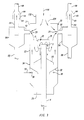
- Fig. 2 shows a detailed side view of the embodiment of Fig. 1.
- Fig. 2 shows that the preferable embodiment of the deflector baffle 12 has a top wall 13 attached to sidewalls 11.
- sidewalls 11 are cylindrical.
- the sidewalls 11 preferably overlap a downstream end 5 of riser 4. This forms an annular opening between the sidewalls 11 and riser 4.
- Regenerated catalyst stream 6 is typically a hot regenerated catalyst, at a temperature of at least 1200°F (649°C), preferably 1250°-1350°F (677°-732°C), to form a gasiform mixture at a temperature of at least 980°F (527°C) in the riser 4.
- Fig. 3 discloses a second embodiment of the present invention which is a modification of that shown by Fig. 2.
- Fig. 3 shows that the stripping vessel 20 has an optional top wall 120 attached to the top of the sidewalls 22 to define a top opening 124 through which a catalyst disengaging vessel atmosphere stream 114 passes from the atmosphere of the disengaging vessel 10 into the stripping vessel 20.
- an inlet conduit 122 is optionally provided and attached to the top wall 120.
- Fig. 4 discloses a detailed side view of the deflector baffle 12 and riser 4 of the present invention.
- An open bottom 15 of deflector baffle 12 has a continuous circumference as shown in Fig. 4.
- Fig. 4 shows that the deflector 12 is a solid cap through which both cracked hydrocarbons and catalyst exit from the bottom 15.
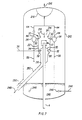
- Fig. 5 shows a deflector baffle 112 which is a modification of deflector baffle 12 of Fig. 4.
- Deflector baffle 112 has slots 130 and teeth 132 along the perimeter at its open bottom 116. A portion of the cracked hydrocarbon vapor discharges through the slot 130 and passes upwardly away from the downwardly directed catalyst. This causes some separation of the catalyst and cracked hydrocarbon vapor prior to discharging the catalyst through the bottom 116.
- Fig. 6 shows a deflector baffle 213 which is a modification of deflector baffle 12 of Fig. 4.
- Fig. 6 shows locating deflector baffle 213 a distance above a riser 204 and axially aligned with riser 204. Thus riser 204 is not inserted into deflector baffle 213.
- Fig. 7 discloses the embodiment of Fig. 1 with modifications to the stripping vessel 20 and a disengaging vessel 210. Stripped catalyst from the first stripping zone defined within lower portion 34 passes into a stripping vessel catalyst exit conduit 350 and is directly discharged from the disengaging vessel 210. Thus, the catalyst from the first stripping zone does not pass through a catalyst bed 240 located within the disengaging vessel 210. Catalyst in the bed 240 is stripped by contact with stripping gas from a second stripping gas conduit 244 attached to a second stripping gas header 246. The catalyst from conduit 350 and bed 240 pass through a catalyst exit conduit 250 as a catalyst exit stream 248. Stream 248 passes to catalyst regeneration or optionally an additional stripping vessel (not shown).
- a disengaging vessel atmosphere stream 214 passes into the stripping vessel 20 through the opening 24 and combines with hydrocarbons stripped away from the catalyst in the lower portion 34 of the vessel 20.
- the combined gas stream then passes through the cyclone inlet conduit 52, cyclone 54, cyclone overhead conduit 56 and enclosed conduit 64 to a plenum chamber 218 and then is discharged through disengaging vessel overhead conduit 216.
- Catalyst separated from the combined stream by cyclone 54 passes through the dipleg 58 to the catalyst bed 240.
- Fig. 8 shows a modification of the embodiment of Fig. 2.
- a top wall 225 is attached to the vessel 20. This closes the opening 24 shown in Fig. 2.
- Fig. 9 shows a modification of the embodiment of Fig. 1.
- the cyclone 54 discharges the gaseous remainder through the cyclone overhead conduit 56 into the atmosphere of the disengaging vessel 10.
- this embodiment employs an open cyclone system. Then the gasiform material in the disengaging vessel atmosphere passes into the plenum chamber 18 and discharges through conduit 16 from the chamber 18.
- the arrangement of the present invention provides many advantages.
- the present invention minimizes contact of cracked hydrocarbon product with catalyst.
- a deflector baffle rather than a riser cyclone, the present invention achieves an initial separation of catalyst and cracked hydrocarbon product quicker than directly discharging catalyst from the riser into a riser cyclone.
- the catalyst passes to a stripping zone quicker than if it had to first pass to a riser cyclone.
- the first stripping zone can be a shorter residence time than required by the entire disengaging vessel.
- Fig. 1 particularly has advantages because employing a deflector baffle, that looks like a large bubble cap, and employing a stripping vessel, is economical to construct. Furthermore, only clean stripping gas from outside of the disengaging vessel passes into the first stripping zone in a lower portion of the stripping vessel. This reduces contact of the main hydrocarbon vapor product, comprising stripped hydrocarbons and vapor from the disengaging vessel atmosphere, with catalyst and thus reduces overcracking. Furthermore, this minimizes undesirable entrainment of catalyst upwardly away from the first stripping zone because only stripping gas passes into the first stripping zone, as opposed to stripping gas and vapor from the disengaging vessel atmosphere.
- Fig. 3 has additional advantages. It provides a narrower opening at the top of the stripping vessel to assist in preventing backflow of vapor from inside the stripping vessel 20 to the disengaging vessel atmosphere.
- the slotted deflector baffle shown by Fig. 5 has an additional advantage. It provides increased separation of catalyst from cracked hydrocarbon vapor prior to passing the catalyst to the first stripping zone.
- the embodiment of Fig. 7 has the particular advantage of reducing catalyst inventory in the disengaging vessel by directly passing catalyst from the first stripping zone to outside the disengaging vessel. This reduces the amount of catalyst in the atmosphere of the stripping vessel and thus reduces the amount of catalyst which can contact with hydrocarbons in the stripping vessel atmosphere.
- Fig. 8 minimizes contact time of gasiform material from the atmosphere of the disengaging vessel and gaseous hydrocarbon product by adding the gasiform material to the gaseous hydrocarbon product only after the gaseous hydrocarbon product discharges from the riser cyclone. Also adding gasiform material to the gaseous hydrocarbon product after the product discharges from the cyclone, rather than before, results in a smaller cyclone and avoids contacting the gasiform material with the catalyst in the cyclone.
- Fig. 9 illustrates that the present invention has the flexibility to be employed with an open cyclone system and still result in quick separation of catalyst from gaseous hydrocarbon product.
Landscapes
- Chemical & Material Sciences (AREA)
- Engineering & Computer Science (AREA)
- Chemical Kinetics & Catalysis (AREA)
- Oil, Petroleum & Natural Gas (AREA)
- Organic Chemistry (AREA)
- General Chemical & Material Sciences (AREA)
- Combustion & Propulsion (AREA)
- Production Of Liquid Hydrocarbon Mixture For Refining Petroleum (AREA)
Applications Claiming Priority (2)
| Application Number | Priority Date | Filing Date | Title |
|---|---|---|---|
| US07/003,677 US4793915A (en) | 1987-01-15 | 1987-01-15 | Short contact time fluid catalytic cracking process |
| US3677 | 1987-01-15 |
Publications (2)
| Publication Number | Publication Date |
|---|---|
| EP0275158A2 true EP0275158A2 (de) | 1988-07-20 |
| EP0275158A3 EP0275158A3 (de) | 1988-10-05 |
Family
ID=21707037
Family Applications (1)
| Application Number | Title | Priority Date | Filing Date |
|---|---|---|---|
| EP88300139A Withdrawn EP0275158A3 (de) | 1987-01-15 | 1988-01-08 | Verfahren und Vorrichtung für das kurzzeitige katalytische Wirbelschichtkracken |
Country Status (6)
| Country | Link |
|---|---|
| US (1) | US4793915A (de) |
| EP (1) | EP0275158A3 (de) |
| JP (1) | JPS63182397A (de) |
| AU (1) | AU609759B2 (de) |
| BR (1) | BR8800087A (de) |
| CA (1) | CA1300542C (de) |
Cited By (4)
| Publication number | Priority date | Publication date | Assignee | Title |
|---|---|---|---|---|
| EP0848051A1 (de) * | 1994-12-27 | 1998-06-17 | Uop | Flüssiges, katalytisches Abbrechen von Kohlenwasserstoff mit integrierter Vorrichtung zum Trennen und 'Stripping' von Katalysatoren |
| EP0952202A1 (de) * | 1998-04-23 | 1999-10-27 | Shell Internationale Researchmaatschappij B.V. | Katalytisch Krack-wirbelbettreaktorsystem |
| AU724751B2 (en) * | 1996-12-17 | 2000-09-28 | Uop | Fluid catalytic cracking of hydrocarbons with integrated apparatus for separating and stripping catalyst |
| EP1800728A1 (de) * | 2005-12-21 | 2007-06-27 | Institut Français du Pétrole | Neuartiges System zur Trennung von Gas und Feststoffen und zum Strippen für die Katkrackeinheiten in einem Wirbelbett |
Families Citing this family (18)
| Publication number | Priority date | Publication date | Assignee | Title |
|---|---|---|---|---|
| US4963328A (en) * | 1987-01-15 | 1990-10-16 | Mobil Oil Corporation | Short contact time fluid catalytic cracking apparatus |
| GB8805755D0 (en) * | 1988-03-10 | 1988-04-07 | Shell Int Research | Apparatus for separation of solids from mixture of solids & fluid |
| US5176815A (en) * | 1990-12-17 | 1993-01-05 | Uop | FCC process with secondary conversion zone |
| US5310477A (en) * | 1990-12-17 | 1994-05-10 | Uop | FCC process with secondary dealkylation zone |
| US5393415A (en) * | 1991-12-06 | 1995-02-28 | Uop | FCC process with enclosed vented riser |
| US5393414A (en) * | 1991-12-06 | 1995-02-28 | Uop | FCC process with enclosed vented riser |
| US5584986A (en) * | 1993-03-19 | 1996-12-17 | Bar-Co Processes Joint Venture | Fluidized process for improved stripping and/or cooling of particulate spent solids, and reduction of sulfur oxide emissions |
| US8747657B2 (en) | 2011-12-12 | 2014-06-10 | Uop Llc | Process and apparatus for mixing two streams of catalyst |
| US8747759B2 (en) | 2011-12-12 | 2014-06-10 | Uop Llc | Process and apparatus for mixing two streams of catalyst |
| US8747758B2 (en) | 2011-12-12 | 2014-06-10 | Uop Llc | Process and apparatus for mixing two streams of catalyst |
| US8815082B2 (en) | 2011-12-12 | 2014-08-26 | Uop Llc | Process and apparatus for mixing two streams of catalyst |
| US8936758B2 (en) | 2012-03-20 | 2015-01-20 | Uop Llc | Process and apparatus for mixing two streams of catalyst |
| US8815166B2 (en) | 2012-03-20 | 2014-08-26 | Uop Llc | Process and apparatus for mixing two streams of catalyst |
| US9375695B2 (en) | 2012-03-20 | 2016-06-28 | Uop Llc | Process and apparatus for mixing two streams of catalyst |
| US8916099B2 (en) | 2012-03-20 | 2014-12-23 | Uop Llc | Process and apparatus for mixing two streams of catalyst |
| US9376633B2 (en) | 2014-03-31 | 2016-06-28 | Uop Llc | Process and apparatus for distributing fluidizing gas to an FCC riser |
| US9205394B2 (en) | 2014-03-31 | 2015-12-08 | Uop Llc | Process and apparatus for distributing fluidizing gas to an FCC riser |
| EP3854772B1 (de) * | 2018-09-27 | 2024-01-17 | Shanghai Supezet Engineering Technology Co., Ltd. | Naphtha katalytisches krackverfahren |
Family Cites Families (24)
| Publication number | Priority date | Publication date | Assignee | Title |
|---|---|---|---|---|
| US3123547A (en) * | 1964-03-03 | Fluidized catalytic cracking process | ||
| US2337684A (en) * | 1941-04-24 | 1943-12-28 | Standard Oil Co | System for recovering finely divided solids from gases |
| US2606097A (en) * | 1947-08-25 | 1952-08-05 | Phillips Petroleum Co | Fluid type catalytic reaction chamber and method of operating same |
| US3243265A (en) * | 1962-12-03 | 1966-03-29 | Chevron Res | Catalytic cracking apparatus |
| US3243215A (en) * | 1963-11-26 | 1966-03-29 | Adams Rite Mfg Company | Window latch |
| US3826738A (en) * | 1972-03-23 | 1974-07-30 | F Zenz | Folded transfer line reactor |
| US3856659A (en) * | 1972-12-19 | 1974-12-24 | Mobil Oil Corp | Multiple reactor fcc system relying upon a dual cracking catalyst composition |
| US4035284A (en) * | 1973-07-18 | 1977-07-12 | Mobil Oil Corporation | Method and system for regenerating fluidizable catalyst particles |
| AT364745B (de) * | 1975-03-24 | 1981-11-10 | Ashland Oil Inc | Verfahren und vorrichtung zum abscheiden feiner feststoffteilchen aus stroemenden gasen |
| US4116814A (en) * | 1977-07-18 | 1978-09-26 | Mobil Oil Corporation | Method and system for effecting catalytic cracking of high boiling hydrocarbons with fluid conversion catalysts |
| US4219407A (en) * | 1978-01-20 | 1980-08-26 | Mobil Oil Corporation | Fluid cracking process and the method for separating a suspension discharged from a riser cracking zone |
| US4206174A (en) * | 1978-02-01 | 1980-06-03 | Mobil Oil Corporation | Means for separating suspensions of gasiform material and fluidizable particles |
| GB2051619A (en) * | 1979-07-02 | 1981-01-21 | Shell Int Research | Separation of gases from particle streams |
| US4295961A (en) * | 1979-11-23 | 1981-10-20 | Standard Oil Company (Indiana) | Method and apparatus for improved fluid catalytic riser reactor cracking of hydrocarbon feedstocks |
| US4500423A (en) * | 1981-02-26 | 1985-02-19 | Chevron Research Company | Separation of reacted hydrocarbons and catalyst in fluidized catalytic cracking |
| US4394349A (en) * | 1981-07-06 | 1983-07-19 | Standard Oil Company (Indiana) | Apparatus for the fluidized catalytic cracking of hydrocarbon feedstock |
| US4404095A (en) * | 1982-07-22 | 1983-09-13 | Mobil Oil Corporation | Method and means for separating gaseous materials from finely divided catalyst particles |
| US4482451A (en) * | 1982-09-16 | 1984-11-13 | Uop Inc. | Process for the separation of particulate solids from vapors using a discharge having a helical twist |
| US4591427A (en) * | 1982-11-24 | 1986-05-27 | Chevron Research Company | Method for vapor recovery for fluidized catalytic cracking processes |
| US4502947A (en) * | 1984-05-21 | 1985-03-05 | Mobil Oil Corporation | Closed cyclone FCC catalyst separation method and apparatus |
| US4605491A (en) * | 1984-07-18 | 1986-08-12 | Mobil Oil Corporation | FCC catalyst stripping method |
| US4572780A (en) * | 1984-10-22 | 1986-02-25 | Mobil Oil Corporation | Multistage stripper for FCC unit with catalyst separation by spinning |
| ZA857398B (en) * | 1984-10-30 | 1987-05-27 | Mobil Oil Corp | Quenched catalytic cracking process |
| AU5115885A (en) * | 1984-12-27 | 1986-07-03 | Mobil Oil Corp. | Fluid catalytic cracking |
-
1987
- 1987-01-15 US US07/003,677 patent/US4793915A/en not_active Expired - Fee Related
- 1987-12-31 AU AU83176/87A patent/AU609759B2/en not_active Ceased
-
1988
- 1988-01-07 CA CA000556033A patent/CA1300542C/en not_active Expired - Lifetime
- 1988-01-08 EP EP88300139A patent/EP0275158A3/de not_active Withdrawn
- 1988-01-12 BR BR8800087A patent/BR8800087A/pt unknown
- 1988-01-14 JP JP63005022A patent/JPS63182397A/ja active Pending
Cited By (4)
| Publication number | Priority date | Publication date | Assignee | Title |
|---|---|---|---|---|
| EP0848051A1 (de) * | 1994-12-27 | 1998-06-17 | Uop | Flüssiges, katalytisches Abbrechen von Kohlenwasserstoff mit integrierter Vorrichtung zum Trennen und 'Stripping' von Katalysatoren |
| AU724751B2 (en) * | 1996-12-17 | 2000-09-28 | Uop | Fluid catalytic cracking of hydrocarbons with integrated apparatus for separating and stripping catalyst |
| EP0952202A1 (de) * | 1998-04-23 | 1999-10-27 | Shell Internationale Researchmaatschappij B.V. | Katalytisch Krack-wirbelbettreaktorsystem |
| EP1800728A1 (de) * | 2005-12-21 | 2007-06-27 | Institut Français du Pétrole | Neuartiges System zur Trennung von Gas und Feststoffen und zum Strippen für die Katkrackeinheiten in einem Wirbelbett |
Also Published As
| Publication number | Publication date |
|---|---|
| EP0275158A3 (de) | 1988-10-05 |
| BR8800087A (pt) | 1988-08-16 |
| AU8317687A (en) | 1988-07-21 |
| CA1300542C (en) | 1992-05-12 |
| AU609759B2 (en) | 1991-05-09 |
| JPS63182397A (ja) | 1988-07-27 |
| US4793915A (en) | 1988-12-27 |
Similar Documents
| Publication | Publication Date | Title |
|---|---|---|
| US4793915A (en) | Short contact time fluid catalytic cracking process | |
| US4502947A (en) | Closed cyclone FCC catalyst separation method and apparatus | |
| US4623446A (en) | Closed cyclone FCC catalyst separation with stripping gas injection and direct steam injection | |
| US4572780A (en) | Multistage stripper for FCC unit with catalyst separation by spinning | |
| US4737346A (en) | Closed cyclone FCC catalyst separation with stripping gas injection and direct steam injection | |
| US4404095A (en) | Method and means for separating gaseous materials from finely divided catalyst particles | |
| EP0139392B1 (de) | Geschlossenes FCC-Reaktor-System mit Vorkehrungen gegen Überschusskapazität | |
| US4689206A (en) | Multistage stripper for FCC unit with improved catalyst separation | |
| EP0488549B1 (de) | Katalysatorabtrennung und Entfernung von Stripping-gas in FCC-Einlagen | |
| US4605491A (en) | FCC catalyst stripping method | |
| US4963328A (en) | Short contact time fluid catalytic cracking apparatus | |
| US4946656A (en) | Vented stripper section for a fluid catalytic cracking unit apparatus | |
| EP0139390B1 (de) | Geschlossenes Cyclon-FCC-System mit Vorkehrungen gegen Überflusskapazität | |
| US5055177A (en) | Closed cyclone FCC catalyst separation method and apparatus | |
| US4624772A (en) | Closed reactor FCC system with provisions for surge capacity | |
| EP1133538B1 (de) | Trennungsgerät | |
| US5039397A (en) | Closed cyclone FCC catalyst separation method and apparatus | |
| US4909993A (en) | Closed cyclone FCC catalyst separation apparatus | |
| US4853187A (en) | Apparatus to reduce NOx emissions from a fluid catalytic cracking unit | |
| US4654060A (en) | Closed cyclone FCC catalyst separation method and apparatus | |
| GB1593157A (en) | Fluid cracking process and the method for separating a suspension discharged from a riser cracking zone | |
| EP0187032A1 (de) | Verfahren und Vorrichtung zum katalytischen Wirbelschichtkracken | |
| EP0169008B1 (de) | Verfahren zum "Stripping"von katalytischen Wirbelschichtspaltungskatalysatoren | |
| US4711712A (en) | Closed cyclone FCC system with provisions for surge capacity | |
| EP0317700A2 (de) | Verfahren und Vorrichtung für das Stripping von katalytischen Wirbelschichtspaltungskatalysatoren |
Legal Events
| Date | Code | Title | Description |
|---|---|---|---|
| PUAI | Public reference made under article 153(3) epc to a published international application that has entered the european phase |
Free format text: ORIGINAL CODE: 0009012 |
|
| AK | Designated contracting states |
Kind code of ref document: A2 Designated state(s): BE DE FR GB IT NL |
|
| PUAL | Search report despatched |
Free format text: ORIGINAL CODE: 0009013 |
|
| AK | Designated contracting states |
Kind code of ref document: A3 Designated state(s): BE DE FR GB IT NL |
|
| 17P | Request for examination filed |
Effective date: 19890309 |
|
| 17Q | First examination report despatched |
Effective date: 19891106 |
|
| STAA | Information on the status of an ep patent application or granted ep patent |
Free format text: STATUS: THE APPLICATION HAS BEEN WITHDRAWN |
|
| 18W | Application withdrawn |
Withdrawal date: 19920617 |