EP0275246A2 - Appareil pour la production de dioxyde de chlore - Google Patents
Appareil pour la production de dioxyde de chlore Download PDFInfo
- Publication number
- EP0275246A2 EP0275246A2 EP88850011A EP88850011A EP0275246A2 EP 0275246 A2 EP0275246 A2 EP 0275246A2 EP 88850011 A EP88850011 A EP 88850011A EP 88850011 A EP88850011 A EP 88850011A EP 0275246 A2 EP0275246 A2 EP 0275246A2
- Authority
- EP
- European Patent Office
- Prior art keywords
- reaction chamber
- chlorine dioxide
- sulfur dioxide
- reaction
- solution
- Prior art date
- Legal status (The legal status is an assumption and is not a legal conclusion. Google has not performed a legal analysis and makes no representation as to the accuracy of the status listed.)
- Withdrawn
Links
- OSVXSBDYLRYLIG-UHFFFAOYSA-N dioxidochlorine(.) Chemical compound O=Cl=O OSVXSBDYLRYLIG-UHFFFAOYSA-N 0.000 title claims abstract description 173
- 235000019398 chlorine dioxide Nutrition 0.000 title claims abstract description 87
- 239000004155 Chlorine dioxide Substances 0.000 title claims abstract description 86
- 238000004519 manufacturing process Methods 0.000 title description 5
- RAHZWNYVWXNFOC-UHFFFAOYSA-N Sulphur dioxide Chemical compound O=S=O RAHZWNYVWXNFOC-UHFFFAOYSA-N 0.000 claims abstract description 115
- 238000006243 chemical reaction Methods 0.000 claims abstract description 102
- QAOWNCQODCNURD-UHFFFAOYSA-N sulfuric acid Substances OS(O)(=O)=O QAOWNCQODCNURD-UHFFFAOYSA-N 0.000 claims abstract description 44
- XTEGARKTQYYJKE-UHFFFAOYSA-M Chlorate Chemical compound [O-]Cl(=O)=O XTEGARKTQYYJKE-UHFFFAOYSA-M 0.000 claims abstract description 29
- 239000000376 reactant Substances 0.000 claims abstract description 22
- 239000012431 aqueous reaction media Substances 0.000 claims abstract description 6
- XLYOFNOQVPJJNP-UHFFFAOYSA-N water Substances O XLYOFNOQVPJJNP-UHFFFAOYSA-N 0.000 claims description 35
- BZSXEZOLBIJVQK-UHFFFAOYSA-N 2-methylsulfonylbenzoic acid Chemical compound CS(=O)(=O)C1=CC=CC=C1C(O)=O BZSXEZOLBIJVQK-UHFFFAOYSA-N 0.000 claims description 17
- 238000011282 treatment Methods 0.000 claims description 12
- 239000002253 acid Substances 0.000 claims description 11
- 238000005086 pumping Methods 0.000 claims description 5
- 239000007795 chemical reaction product Substances 0.000 claims description 3
- 239000012530 fluid Substances 0.000 claims 6
- 239000002351 wastewater Substances 0.000 claims 1
- 239000012429 reaction media Substances 0.000 abstract description 12
- 229920006362 Teflon® Polymers 0.000 abstract description 8
- 239000004809 Teflon Substances 0.000 abstract description 7
- 238000001816 cooling Methods 0.000 abstract description 6
- 230000000979 retarding effect Effects 0.000 abstract description 3
- 238000004090 dissolution Methods 0.000 abstract description 2
- 238000002360 preparation method Methods 0.000 abstract description 2
- 239000007789 gas Substances 0.000 description 29
- 239000000243 solution Substances 0.000 description 23
- 239000000047 product Substances 0.000 description 13
- 239000007864 aqueous solution Substances 0.000 description 9
- 238000000034 method Methods 0.000 description 9
- 239000007788 liquid Substances 0.000 description 8
- ZAMOUSCENKQFHK-UHFFFAOYSA-N Chlorine atom Chemical compound [Cl] ZAMOUSCENKQFHK-UHFFFAOYSA-N 0.000 description 7
- 239000006227 byproduct Substances 0.000 description 7
- 239000000460 chlorine Substances 0.000 description 7
- 229910052801 chlorine Inorganic materials 0.000 description 7
- 239000007792 gaseous phase Substances 0.000 description 5
- 239000012071 phase Substances 0.000 description 5
- 239000004033 plastic Substances 0.000 description 5
- VEXZGXHMUGYJMC-UHFFFAOYSA-N Hydrochloric acid Chemical compound Cl VEXZGXHMUGYJMC-UHFFFAOYSA-N 0.000 description 4
- 150000001875 compounds Chemical class 0.000 description 4
- 230000000694 effects Effects 0.000 description 4
- 239000002609 medium Substances 0.000 description 4
- 230000015572 biosynthetic process Effects 0.000 description 3
- 238000010790 dilution Methods 0.000 description 3
- 239000012895 dilution Substances 0.000 description 3
- NBVXSUQYWXRMNV-UHFFFAOYSA-N fluoromethane Chemical compound FC NBVXSUQYWXRMNV-UHFFFAOYSA-N 0.000 description 3
- 239000007791 liquid phase Substances 0.000 description 3
- 238000010276 construction Methods 0.000 description 2
- 239000000110 cooling liquid Substances 0.000 description 2
- 239000000498 cooling water Substances 0.000 description 2
- 238000000354 decomposition reaction Methods 0.000 description 2
- 239000012527 feed solution Substances 0.000 description 2
- -1 hydrochloric acid Chemical compound 0.000 description 2
- 229910052751 metal Inorganic materials 0.000 description 2
- 239000002184 metal Substances 0.000 description 2
- 239000000203 mixture Substances 0.000 description 2
- 238000012545 processing Methods 0.000 description 2
- 235000011149 sulphuric acid Nutrition 0.000 description 2
- BQCIDUSAKPWEOX-UHFFFAOYSA-N 1,1-Difluoroethene Chemical compound FC(F)=C BQCIDUSAKPWEOX-UHFFFAOYSA-N 0.000 description 1
- 229920006370 Kynar Polymers 0.000 description 1
- 239000002033 PVDF binder Substances 0.000 description 1
- QAOWNCQODCNURD-UHFFFAOYSA-L Sulfate Chemical compound [O-]S([O-])(=O)=O QAOWNCQODCNURD-UHFFFAOYSA-L 0.000 description 1
- NINIDFKCEFEMDL-UHFFFAOYSA-N Sulfur Chemical compound [S] NINIDFKCEFEMDL-UHFFFAOYSA-N 0.000 description 1
- 238000010521 absorption reaction Methods 0.000 description 1
- 150000007513 acids Chemical class 0.000 description 1
- 230000004075 alteration Effects 0.000 description 1
- 239000011260 aqueous acid Substances 0.000 description 1
- 239000012736 aqueous medium Substances 0.000 description 1
- 231100000357 carcinogen Toxicity 0.000 description 1
- 239000003183 carcinogenic agent Substances 0.000 description 1
- VSQHTVCBHFZBOT-UHFFFAOYSA-M cesium;chlorate Chemical compound [Cs+].[O-]Cl(=O)=O VSQHTVCBHFZBOT-UHFFFAOYSA-M 0.000 description 1
- 239000003795 chemical substances by application Substances 0.000 description 1
- 229940005989 chlorate ion Drugs 0.000 description 1
- QBWCMBCROVPCKQ-UHFFFAOYSA-N chlorous acid Chemical compound OCl=O QBWCMBCROVPCKQ-UHFFFAOYSA-N 0.000 description 1
- 238000009826 distribution Methods 0.000 description 1
- 238000005516 engineering process Methods 0.000 description 1
- 230000002708 enhancing effect Effects 0.000 description 1
- 239000002360 explosive Substances 0.000 description 1
- 239000011521 glass Substances 0.000 description 1
- XQHAGELNRSUUGU-UHFFFAOYSA-M lithium chlorate Chemical compound [Li+].[O-]Cl(=O)=O XQHAGELNRSUUGU-UHFFFAOYSA-M 0.000 description 1
- 238000012423 maintenance Methods 0.000 description 1
- 230000003641 microbiacidal effect Effects 0.000 description 1
- 238000002156 mixing Methods 0.000 description 1
- 238000012986 modification Methods 0.000 description 1
- 230000004048 modification Effects 0.000 description 1
- 150000002894 organic compounds Chemical class 0.000 description 1
- 239000011368 organic material Substances 0.000 description 1
- 229920002981 polyvinylidene fluoride Polymers 0.000 description 1
- 239000011148 porous material Substances 0.000 description 1
- VKJKEPKFPUWCAS-UHFFFAOYSA-M potassium chlorate Chemical compound [K+].[O-]Cl(=O)=O VKJKEPKFPUWCAS-UHFFFAOYSA-M 0.000 description 1
- 230000002035 prolonged effect Effects 0.000 description 1
- 230000010349 pulsation Effects 0.000 description 1
- 239000011541 reaction mixture Substances 0.000 description 1
- 230000001105 regulatory effect Effects 0.000 description 1
- 229920005989 resin Polymers 0.000 description 1
- 239000011347 resin Substances 0.000 description 1
- 238000012552 review Methods 0.000 description 1
- GZXRGRLACABJNC-UHFFFAOYSA-M rubidium(1+);chlorate Chemical compound [Rb+].[O-]Cl(=O)=O GZXRGRLACABJNC-UHFFFAOYSA-M 0.000 description 1
- UKLNMMHNWFDKNT-UHFFFAOYSA-M sodium chlorite Chemical compound [Na+].[O-]Cl=O UKLNMMHNWFDKNT-UHFFFAOYSA-M 0.000 description 1
- 229960002218 sodium chlorite Drugs 0.000 description 1
- 239000007787 solid Substances 0.000 description 1
- 239000011593 sulfur Substances 0.000 description 1
- 229910052717 sulfur Inorganic materials 0.000 description 1
- 238000004065 wastewater treatment Methods 0.000 description 1
Images
Classifications
-
- F—MECHANICAL ENGINEERING; LIGHTING; HEATING; WEAPONS; BLASTING
- F28—HEAT EXCHANGE IN GENERAL
- F28F—DETAILS OF HEAT-EXCHANGE AND HEAT-TRANSFER APPARATUS, OF GENERAL APPLICATION
- F28F21/00—Constructions of heat-exchange apparatus characterised by the selection of particular materials
- F28F21/06—Constructions of heat-exchange apparatus characterised by the selection of particular materials of plastics material
- F28F21/062—Constructions of heat-exchange apparatus characterised by the selection of particular materials of plastics material the heat-exchange apparatus employing tubular conduits
-
- C—CHEMISTRY; METALLURGY
- C01—INORGANIC CHEMISTRY
- C01B—NON-METALLIC ELEMENTS; COMPOUNDS THEREOF; METALLOIDS OR COMPOUNDS THEREOF NOT COVERED BY SUBCLASS C01C
- C01B11/00—Oxides or oxyacids of halogens; Salts thereof
- C01B11/02—Oxides of chlorine
- C01B11/022—Chlorine dioxide (ClO2)
- C01B11/023—Preparation from chlorites or chlorates
-
- B—PERFORMING OPERATIONS; TRANSPORTING
- B01—PHYSICAL OR CHEMICAL PROCESSES OR APPARATUS IN GENERAL
- B01J—CHEMICAL OR PHYSICAL PROCESSES, e.g. CATALYSIS OR COLLOID CHEMISTRY; THEIR RELEVANT APPARATUS
- B01J2219/00—Chemical, physical or physico-chemical processes in general; Their relevant apparatus
- B01J2219/00049—Controlling or regulating processes
- B01J2219/00051—Controlling the temperature
- B01J2219/00074—Controlling the temperature by indirect heating or cooling employing heat exchange fluids
- B01J2219/00076—Controlling the temperature by indirect heating or cooling employing heat exchange fluids with heat exchange elements inside the reactor
- B01J2219/00081—Tubes
-
- B—PERFORMING OPERATIONS; TRANSPORTING
- B01—PHYSICAL OR CHEMICAL PROCESSES OR APPARATUS IN GENERAL
- B01J—CHEMICAL OR PHYSICAL PROCESSES, e.g. CATALYSIS OR COLLOID CHEMISTRY; THEIR RELEVANT APPARATUS
- B01J2219/00—Chemical, physical or physico-chemical processes in general; Their relevant apparatus
- B01J2219/00049—Controlling or regulating processes
- B01J2219/00162—Controlling or regulating processes controlling the pressure
Definitions
- the present invention relates to an improved system or apparatus for the production of chlorine dioxide and more particularly to a improved chlorine dioxide generator that is small and is suitable for water treatment, waste water treatment, cooling tower water treatment, and for food processing applications.
- Chlorine dioxide is utilized in a variety of processes, including a large number of microbiocidal applications, and especially in the field of water treatment and odor abatement. Because the compound is especially useful in these applications, the usage of chlorine dioxide is continuing to grow.
- the prior art discloses a variety of different types of on-site chlorine dioxide generators, most of which comprise elongated glass or plastic columns of various constructions.
- the column contains an aqueous solution of chlorine dioxide generating reactants.
- the reactants are introduced into the reaction chamber where they are allowed to react to produce chlorine dioxide.
- the chlorine dioxide is usually removed as a gas.
- chlorine dioxide is formed in a reaction zone from chlorine dioxide-generating reactants in an aqueous acid reaction medium, and is removed from the reaction zone as a gaseous product stream.
- the partial pressure of chlorine dioxide in the gaseous product stream is maintained sufficiently low to prevent decomposition of the chlorine dioxide.
- the chlorine dioxide gas is then dissolved in water for later use or is dissolved directly in the water to be treated.
- previous efforts at producing chlorine dioxide in a small compact unit with high yield, short residence time and high production rates have been based on sodium chlorite chemistry which is expensive when compared to chlorate chemistry.
- U.S. Patent 4,451,444 describes a method and apparatus for producing chlorine dioxide that uses the reactants sodium chlorate, sulfuric acid and sulfur dioxide.
- the above method requires a large processing apparatus and produces chlorine dioxide in the gaseous phase.
- the present invention comprises an improved apparatus for producing a product from a liquid and a gaseous reactant comprising an enclosed reaction chamber for housing a liquid reaction medium.
- the reaction chamber has a means for introducing a liquid reactant and a means for introducing a gaseous reactant.
- There is also an outlet means for removing the product which can be either a gas or a liquid.
- the preferred embodiment of the present invention is an improved chlorine dioxide generating process comprising a chlorine dioxide generating apparatus with an unusually small reaction chamber.
- the preferred reactants for producing the chlorine dioxide are sulfuric acid, sodium chlorate and sulfur dioxide gas.
- the chemical reaction which takes place between the sulfur dioxide and the chlorate in this process may summarily be represented by the following reaction in which Me symbolizes a metal atom: 2MeClO3 + SO2 + H2SO4 ⁇ 2ClO2 + 2MeHSO4
- the sulfur dioxide reduces the chlorate ion with the resulting formation of chlorine dioxide and a metal sulfate.
- Chlorine dioxide produced from these reactants has very little chlorine produced as a by-product, thereby reducing the probability of forming undesirable chlorinated organic by-products. If production of chlorine as a by-product is not a problem, then an acid other than sulfuric acid, such as hydrochloric acid, can be used in the reaction.
- the improved chlorine dioxide generating system of the present invention comprises a gas distribution medium mounted in the bottom of a reaction chamber for injecting gaseous sulfur dioxide into the chamber.
- the gas distributor uses porous fluorocarbon plate inserted therein through which the sulfur dioxide is forced.
- the porous fluorocarbon medium breaks the sulfur dioxide gas into extremely fine bubbles, thereby enhancing the solubility of the sulfur dioxide in the aqueous reaction medium.
- the improved chlorine dioxide generating system of the present invention uses pure sulfur dioxide gas without the addition of dilution air to eliminate the bulk of the gas phase in the reaction chamber and to assist in keeping the gaseous product dissolved in the aqueous solution. Since sulfur dioxide absorption in the liquid phase is deemed crucial to an efficient liquid phase reaction, the use of pure sulfur dioxide vapor instead of dilute sulfur dioxide in air will further enhance the solubility of the sulfur dioxide in the aqueous reaction medium.
- Chlorate solution and sulfuric acid are introduced into the reaction chamber through liquid inlets located on the sides of the reaction chamber.
- the present invention also comprises a cooling water tube bundle inside the reaction chamber that, not only cools the reaction medium, but also provides a tortuous path for the gaseous sulfur dioxide to travel as it rises through the reaction solution thereby retarding the sulfur dioxide bubbles and allowing increased contact with the dissolved reactants.
- the chemical reaction inside the chamber will be carried out under superatmospheric pressure so that the chlorine dioxide produced by the reaction will remain dissolved in the aqueous effluent reducing the possibility of explosive decomposition.
- the preferred method of providing the superatmospheric pressure is by pumping water from the untreated water supply to the vicinity of the generator through a back pressure control device to maintain a suitable back pressure on the water stream.
- the product outlet connection at the top of the reaction chamber is directly connected to this pressurized water line, causing a similar back pressure to be developed in both the water piping and the reaction chamber.
- the reactor effluent with the chlorine dioxide dissolved therein is immediately mixed with this pressurized water stream to further promote chlorine dioxide solubility.
- the pressurized stream of water with the chlorine dioxide dissolved therein is then injected into the main stream of water to be treated.
- Another object of the present invention is to provide an improved method of producing chlorine dioxide.
- Another object of the present invention is to provide an improved chlorine dioxide generator that can be used on-site.
- Another object of the present invention is to provide an improved chlorine dioxide generator that does not produce chlorine dioxide in the gaseous phase and is therefore safe to use.
- Yet a further object of the present invention is to provide an improved chlorine dioxide generator that utilizes pressurized water to produce the necessary reaction chamber back pressure.
- Another object of the present invention is to provide an improved chlorine dioxide generator which utilizes sulfuric acid, sulfur dioxide, and sodium chlorate as reactants.
- Another object of the present invention is to provide an improved chlorine dioxide generator in which pure sulfur dioxide gas is dispersed into the reaction chamber as very fine bubbles to enhance sulfur dioxide solubility.
- Another object of the present invention is to provide an improved chlorine dioxide generator in which the sulfur dioxide is introduced as nearly pure sulfur dioxide vapor to further enhance the solubility of the sulfur dioxide in the aqueous medium.
- Another object of the present invention is to provide an improved chlorine dioxide generator that has a small reaction chamber with a cooling water tube bundle which both cools the reaction medium and also retards the upward movement of sulfur dioxide bubbles.
- an improved apparatus for the preparation of chlorine dioxide which employs an improved chlorine dioxide generator comprising a small reaction chamber with means for injecting a concentrated metallic chlorate solution, a concentrated sulfuric acid solution, and gaseous sulfur dioxide.
- the metallic chlorate used in the present invention includes, but is not limited to, lithium chlorate, sodium chlorate, potassium chlorate, rubidium chlorate, and cesium chlorate.
- the sulfur dioxide gas is injected into the reaction chamber from the bottom through a porous medium which disperses the gas as extremely fine bubbles of approximately 30 to 100 ⁇ m in diameter into the aqueous reaction medium in the chamber.
- the reaction chamber is equipped with an internal teflon braided cooling coil inserted therein which not only cools the reaction medium but also provides a tortuous path for the sulfur dioxide bubbles. By retarding the upward path of the bubbles, the sulfur dioxide is held in solution for a longer period of time allowing more time for reactant gas dissolution and corresponding chemical reaction.
- the reaction chamber is maintained under superatmospheric pressure so that the chlorine dioxide that is produced is maintained in solution. Keeping the reaction chamber under pressure, as opposed to atmospheric pressure operation, also promotes sulfur dioxide solubility. Because the chlorine dioxide isn't handled in a separate gas phase, operation of the unit is more simple and inherently safer than prior art systems which handle chlorine dioxide as a gas.
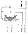
- the improved chlorine dioxide generator of the present invention is best understood by reference to the accompanying drawings.
- the chlorine dioxide generator comprises a columnar cylindrical reaction chamber 15 containing a braided teflon cooling coil 65.
- the coil 65 is loosely packed into the reaction chamber to fill the cross-section thereof.
- Suflur dioxide gas, vaporized in a conventional manner, is fed along a pipe 45 to a check valve 21 and into the reaction chamber 15 at inlet 20 through a porous plastic media 23 at the bottom of the reaction chamber 15.
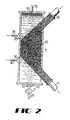
- the porous plastic media 23 is inserted in the path of the sulfur dioxide gas at inlet 20 (See Fig. 2).
- the porous plastic media in the preferred embodiment is a .25 inch thick PVDF (Kynar) sheet with a 25 ⁇ m average pore size (Porex Technologies, Fairburn, Georgia). It is to be understood that liquid sulfur dioxide can be introduced into the reaction chamber 15. The pressure in the chamber can be adjusted so that the liquid sulfur dioxide remains in the liquid phase or enters the gaseous phase after introduction into the chamber 15.
- the reaction chamber 15 also has liquid inlets 25 and 30 fitted with check valves and located on the sides of the reaction chamber 15.
- Aqueous solutions of sodium chlorate and sulfuric acid are pumped to the reaction chamber 15 via pipes 35 and 40 by suitable metering pumps 36 and 41 with pulsation dampeners (not shown) and terminating in the inlets 25 and 30, respectively.
- inlets 25 and 30 are located on the reaction chamber 15.
- the inlet through which the acid is introduced should be located near the bottom of the reaction chamber, below the chlorate solution inlet and the inlet through which the metallic chlorate solution is introduced should be located a sufficient distance above the acid inlet so that the acid is substantially fully diluted with the reaction medium before contacting the chlorate solution.
- the acid solution is immediately placed in contact with the sulfur dioxide gas as the gas is introduced into the chamber.
- the acid-sulfur dioxide solution then comes into contact with the metallic chlorate solution.
- sulfuric acid is used as the acid component in the reaction, it is to be understood that other acids, such as hydrochloric acid, can be used in practicing the present invention.
- the concentration of sodium chlorate in the aqueous feed solution may vary from about 1.9 to about 6.1 molar, typically about 3.3 molar.
- the concentration of sulfuric acid in the aqueous feed solution may vary from about 10.5 to about 17.3 molar, typically about 14 molar.
- Usually the molar proportions of sodium chlorate to sulfuric acid is about 0.4 : 1 to about 0.6:1.
- the temperature at which the reaction proceeds in the reaction chamber 15 is between approximately 80°F and 130°F with the preferred temperature of between about 90°F and 115°F and the especially preferred temperature of about 100°F.
- reaction chamber 15 At the top of reaction chamber 15 is an outlet 53 for removing the solution of chlorine dioxide via pipe 55.
- the chlorine dioxide solution is transported to pipe 60 which carries untreated water.
- the chlorine dioxide solution is then injected into the untreated water stream at 74.
- reaction chamber 15 contains a braided cooling coil 65 which, in the preferred embodiment, is comprised of braided tubing made from teflon fluorocarbon resins.
- the reaction chamber 15 is fitted with a Teflon® Model 650 braided heat exchanger 65 (Ametek Inc., Wilmington, DE) which provides a tortuous path for the sulfur dioxide gas bubbles which are injected into the bottom of the reaction chamber.
- the heat exchanger 65 comprises a plurality of small-diameter braided teflon tubes connected at each end to fittings 67 and 69.
- a cooling liquid can be circulated through the tubes via fittings 67 and 69.
- the preferred cooling liquid is water.
- the teflon braided heat exchanger retards the upward path of the bubbles thereby causing the sulfur dioxide bubbles to be in contact with the sodium chlorate and sulfuric acid in solution for a longer period of time and promotes solubility of the sulfur dioxide gas in the aqueous reaction medium. This allows a more complete reaction to form chlorine dioxide in the smaller volume of aqueous reactant medium. It is to be understood that any single or separate means that provides both a tortuous path for the sulfur dioxide bubbles and adequate heat removal could be used in the reaction chamber in accordance with the present invention.
- the reaction medium comprising the solution of sulfuric acid, sodium chlorate and sulfur dioxide gas, fills the reaction chamber 15, and is subjected to elevated pressure therein to substantially prevent the formation of a continuous phase of gaseous chlorine dioxide and substantially retain the chlorine dioxide gas in the reaction chamber effluent.
- the pressure is maintained between about 50 to about 150 psig, preferably between about 80 to about 100 psig, in the reaction chamber.
- pressure in the reaction chamber 15 is maintained by piping untreated water through pipe 70 by pump 72 into pipe 55 at inlet 77. Pumping untreated water in this manner provides a back pressure into reaction chamber 15. Pressure in the reaction chamber 15 is regulated by a back pressure control device 71.
- reaction chamber 15 must be great enough to keep substantially all of the chlorine dioxide produced in chamber 15 in solution.
- the pressurized solution of chlorine dioxide in the spent reaction medium in reaction chamber 15 is discharged from the reaction chamber 15 through pipe 55 to water 58 flowing in pipe 60 after a residence time at least sufficient to effect substantially complete reaction of the sulfur dioxide in the reaction chamber. Residence time is controlled by the rate of introduction of the sodium chlorate/sulfuric acid solutions.
- the discharge of the diluted reactor effluent into the untreated water 58 flowing in pipe 60 achieves substantial dilution of the chlorine dioxide, so that the gas remains dissolved and effects the desired treatment of the water 58 in the pipe 60.
- an aqueous solution of sodium chlorate and sulfuric acid enters the reaction chamber 15 through inlet valves 25 and 30 respectively.
- Sulfur dioxide gas enters the reaction chamber 15 through check valve 21 just before the inlet 20 located at the bottom of reaction chamber 15.
- Inlet 20 contains a porous plastic media 23 which disperses the gas into the reaction solution as small bubbles (See Fig. 2).
- the braided teflon cooling coil 65 which is installed in the reaction chamber 15, retards the upward movement of the sulfur dioxide bubbles allowing prolonged contact of the sulfur dioxide bubbles with the dissolved sulfuric acid and sodium chlorate in the reaction medium.
- the improved chlorine dioxide generator of the present invention 10 is simple in construction, easy to operate and requires little maintenance. Chlorine dioxide can be produced rapidly at high yield and efficiency as an aqueous solution in the spent reaction medium. No gaseous products are produced and the equipment required for handling gaseous reaction products is thereby eliminated.
- a small scale chlorine dioxide generation system is operated continuously, with a sodium chlorate feed consisting of 3.22 gallons per hour of 600 gram per liter NaClO3 solution, a sulfuric acid feed consisting of 2.10 gallons per hour of 93 wt.% H2SO4 solution, and a sulfur dioxide feed consisting of 0.112 ACFM (6.42 pounds per hour) of anhydrous sulfur dioxide gas.
- the reaction chamber is maintained at a pressure of about 90 PSIG, and a temperature of 100°F.
- the reactor effluent is removed from the reaction chamber at a rate of 7.11 gallons per hour of an aqueous solution containing 8.33 pounds per hour of dissolved chlorine dioxide along with some unreacted sodium chlorate and sulfuric acid, and additional dissolved by-products of the reaction.
- the reactor effluent stream is mixed with a slipstream of 2.5 gallons per minute of untreated water from a water treatment facility. This combined stream is then injected into 6664 gallons per minute of untreated water, resulting in a 2.5 ppm ClO2 concentration in the main untreated water stream.
- up to 200 pounds of chlorine dioxide are produced per 24 hour day to effect the desired treatment of up to 9.6 million gallons per 24 hour day of untreated water.
Landscapes
- Chemical & Material Sciences (AREA)
- Engineering & Computer Science (AREA)
- Organic Chemistry (AREA)
- Physics & Mathematics (AREA)
- Inorganic Chemistry (AREA)
- Geology (AREA)
- Life Sciences & Earth Sciences (AREA)
- Thermal Sciences (AREA)
- General Life Sciences & Earth Sciences (AREA)
- Mechanical Engineering (AREA)
- General Engineering & Computer Science (AREA)
- Physical Or Chemical Processes And Apparatus (AREA)
- Feeding, Discharge, Calcimining, Fusing, And Gas-Generation Devices (AREA)
- Treating Waste Gases (AREA)
Applications Claiming Priority (2)
| Application Number | Priority Date | Filing Date | Title |
|---|---|---|---|
| US408687A | 1987-01-15 | 1987-01-15 | |
| US4086 | 1987-01-15 |
Publications (2)
| Publication Number | Publication Date |
|---|---|
| EP0275246A2 true EP0275246A2 (fr) | 1988-07-20 |
| EP0275246A3 EP0275246A3 (fr) | 1988-09-21 |
Family
ID=21709066
Family Applications (1)
| Application Number | Title | Priority Date | Filing Date |
|---|---|---|---|
| EP88850011A Withdrawn EP0275246A3 (fr) | 1987-01-15 | 1988-01-14 | Appareil pour la production de dioxyde de chlore |
Country Status (2)
| Country | Link |
|---|---|
| EP (1) | EP0275246A3 (fr) |
| CA (1) | CA1317093C (fr) |
Cited By (4)
| Publication number | Priority date | Publication date | Assignee | Title |
|---|---|---|---|---|
| US5061471A (en) * | 1990-04-26 | 1991-10-29 | Eka Nobel Ab | Process for the production of chlorine dioxide |
| WO1995011418A1 (fr) * | 1993-10-20 | 1995-04-27 | E.I. Du Pont De Nemours And Company | Procede et appareil pour faire reagir un gaz et un liquide dans un reseau de tubes en volute |
| US8168153B2 (en) | 2007-07-13 | 2012-05-01 | Akzo Nobel N.V. | Process for the production of chlorine dioxide |
| EP3962542A4 (fr) * | 2019-06-05 | 2023-01-11 | Dripping Wet Water, Inc. | Production catalytique sous pression d'espèces de dioxyde |
Family Cites Families (3)
| Publication number | Priority date | Publication date | Assignee | Title |
|---|---|---|---|---|
| US2598087A (en) * | 1949-06-02 | 1952-05-27 | Int Paper Canada | Method for producing chlorine dioxide |
| FR2383122A2 (fr) * | 1977-03-07 | 1978-10-06 | Chimiques | Procede et installation pour la fabrication du bioxyde de chlore |
| US4451444A (en) * | 1981-10-21 | 1984-05-29 | Lamb-Weston, Inc. | Method and apparatus for producing chlorine dioxide |
-
1988
- 1988-01-12 CA CA000556325A patent/CA1317093C/fr not_active Expired - Lifetime
- 1988-01-14 EP EP88850011A patent/EP0275246A3/fr not_active Withdrawn
Cited By (4)
| Publication number | Priority date | Publication date | Assignee | Title |
|---|---|---|---|---|
| US5061471A (en) * | 1990-04-26 | 1991-10-29 | Eka Nobel Ab | Process for the production of chlorine dioxide |
| WO1995011418A1 (fr) * | 1993-10-20 | 1995-04-27 | E.I. Du Pont De Nemours And Company | Procede et appareil pour faire reagir un gaz et un liquide dans un reseau de tubes en volute |
| US8168153B2 (en) | 2007-07-13 | 2012-05-01 | Akzo Nobel N.V. | Process for the production of chlorine dioxide |
| EP3962542A4 (fr) * | 2019-06-05 | 2023-01-11 | Dripping Wet Water, Inc. | Production catalytique sous pression d'espèces de dioxyde |
Also Published As
| Publication number | Publication date |
|---|---|
| EP0275246A3 (fr) | 1988-09-21 |
| CA1317093C (fr) | 1993-05-04 |
Similar Documents
| Publication | Publication Date | Title |
|---|---|---|
| CA2710069C (fr) | Procede pour le traitement de l'eau avec du dioxyde de chlore | |
| US4247531A (en) | Chlorine dioxide generation apparatus and process | |
| US8486276B2 (en) | Method of treating water and aqueous systems in pipes with chlorine dioxide | |
| US4234446A (en) | Method and apparatus for producing chlorine dioxide | |
| US20070178021A1 (en) | Method and Apparatus for Generating Gaseous Chlorine Dioxide-Chlorine Mixtures | |
| US20070237708A1 (en) | Process for the production of chlorine dioxide | |
| US4451444A (en) | Method and apparatus for producing chlorine dioxide | |
| CN100471791C (zh) | 二氧化氯的生产方法 | |
| US5439663A (en) | Method for producing Caro's acid | |
| EP0275246A2 (fr) | Appareil pour la production de dioxyde de chlore | |
| US4839152A (en) | Process for producing an aqueous solution containing chlorine dioxide and chlorine | |
| RU2055808C1 (ru) | Способ получения двуокиси хлора | |
| AU685996B2 (en) | Method for producing caro's acid | |
| US5061471A (en) | Process for the production of chlorine dioxide | |
| CA2648673C (fr) | Procede de fabrication de dioxyde de chlore | |
| JP4457114B2 (ja) | 二酸化塩素の製造方法 | |
| US5279717A (en) | Process for removing chlorate salt from aqueous alkali chloride solution | |
| RU2404118C2 (ru) | Способ получения диоксида хлора | |
| HK1137409A (en) | Method of treating water with chlorine dioxide |
Legal Events
| Date | Code | Title | Description |
|---|---|---|---|
| PUAI | Public reference made under article 153(3) epc to a published international application that has entered the european phase |
Free format text: ORIGINAL CODE: 0009012 |
|
| AK | Designated contracting states |
Kind code of ref document: A2 Designated state(s): AT BE CH DE ES FR GB IT LI LU NL SE |
|
| PUAL | Search report despatched |
Free format text: ORIGINAL CODE: 0009013 |
|
| AK | Designated contracting states |
Kind code of ref document: A3 Designated state(s): AT BE CH DE ES FR GB IT LI LU NL SE |
|
| 17P | Request for examination filed |
Effective date: 19890227 |
|
| 17Q | First examination report despatched |
Effective date: 19910923 |
|
| STAA | Information on the status of an ep patent application or granted ep patent |
Free format text: STATUS: THE APPLICATION IS DEEMED TO BE WITHDRAWN |
|
| 18D | Application deemed to be withdrawn |
Effective date: 19920204 |