EP0275385B1 - Guide-fil pour machines textiles - Google Patents
Guide-fil pour machines textiles Download PDFInfo
- Publication number
- EP0275385B1 EP0275385B1 EP87116375A EP87116375A EP0275385B1 EP 0275385 B1 EP0275385 B1 EP 0275385B1 EP 87116375 A EP87116375 A EP 87116375A EP 87116375 A EP87116375 A EP 87116375A EP 0275385 B1 EP0275385 B1 EP 0275385B1
- Authority
- EP
- European Patent Office
- Prior art keywords
- thread
- flat knitting
- knitting machine
- thread guide
- wires
- Prior art date
- Legal status (The legal status is an assumption and is not a legal conclusion. Google has not performed a legal analysis and makes no representation as to the accuracy of the status listed.)
- Expired - Lifetime
Links
- 239000004753 textile Substances 0.000 title description 3
- 238000009940 knitting Methods 0.000 claims description 17
- 238000004804 winding Methods 0.000 claims description 2
- 239000000969 carrier Substances 0.000 claims 1
- 230000037431 insertion Effects 0.000 claims 1
- 238000003780 insertion Methods 0.000 claims 1
- 230000000694 effects Effects 0.000 description 2
- 238000005299 abrasion Methods 0.000 description 1
- 238000004873 anchoring Methods 0.000 description 1
- 239000000835 fiber Substances 0.000 description 1
- 239000002184 metal Substances 0.000 description 1
- 238000007665 sagging Methods 0.000 description 1
Images


Classifications
-
- D—TEXTILES; PAPER
- D04—BRAIDING; LACE-MAKING; KNITTING; TRIMMINGS; NON-WOVEN FABRICS
- D04B—KNITTING
- D04B15/00—Details of, or auxiliary devices incorporated in, weft knitting machines, restricted to machines of this kind
- D04B15/38—Devices for supplying, feeding, or guiding threads to needles
- D04B15/54—Thread guides
-
- B—PERFORMING OPERATIONS; TRANSPORTING
- B65—CONVEYING; PACKING; STORING; HANDLING THIN OR FILAMENTARY MATERIAL
- B65H—HANDLING THIN OR FILAMENTARY MATERIAL, e.g. SHEETS, WEBS, CABLES
- B65H57/00—Guides for filamentary materials; Supports therefor
- B65H57/02—Stationary rods or plates
-
- B—PERFORMING OPERATIONS; TRANSPORTING
- B65—CONVEYING; PACKING; STORING; HANDLING THIN OR FILAMENTARY MATERIAL
- B65H—HANDLING THIN OR FILAMENTARY MATERIAL, e.g. SHEETS, WEBS, CABLES
- B65H2701/00—Handled material; Storage means
- B65H2701/30—Handled filamentary material
- B65H2701/31—Textiles threads or artificial strands of filaments
Definitions
- the invention relates to a flat knitting machine with the features listed in the preamble of the main claim.
- the threads are guided from a thread storage point to a thread processing point largely freely between thread guide eyes forming thread deflection points. Through additional devices, the thread experiences a sufficient tension that keeps it in its guideway. It is also known to guide the thread in a tube in protected areas of textile machines. With heavy yarns, in particular yarns provided with metal threads, the risk of sagging increases with freely guided yarns. This danger is particularly present in flat knitting machines, where the yarns have to run horizontally and without guidance over long distances from the needle bed ends to thread guides which can be moved in both directions. Here you can the yarns are also not guided in tubes, which carry the risk of clogging due to fiber abrasion anyway.
- the invention has for its object to provide a thread guide element for flat knitting machines with which an undesirable sag of an openly guided yarn or thread is avoided without obstructing the thread path.
- US-A-4,186,549 discloses a pivotable rod as thread guide element in a thread winding machine, around which a twisted thread is wrapped in several turns in order to prevent it from hanging freely and thereby being able to untwist.
- the thread tension should also be increased, which additionally prevents the thread from unraveling.
- the thread guide element solves another task there with the disadvantage that applies to flat knitting machines that there is an increase in the set thread tension, which has a disadvantageous effect on the knitted pattern. With flat knitting machines, low-friction thread guidance must be ensured.
- the smooth guide body serves as a support for the open thread. Since the thread on the guide body is not in numerous turns is wound, but only loosely rests in a few places, the braking effect of the guide body on the moving thread is so low that it can be accepted.
- At least one guide body in the form of a tensioned wire can advantageously be guided parallel to each thread guide rail.
- several tensioned wires are arranged as guide bodies at a distance from each other below the thread guide rail in the areas between the thread guide arms, which extend over the entire active length of the needle beds.
- the wires can advantageously be kept permanently under tension by tension springs, as a result of which age-related extensions of such wires, for example plastic wires, can also be compensated for.
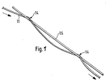
- Fig. 1 shows a guide body in the form of a tensioned wire 15, around which a moving thread 11 is loosely laid with a few turns, so that it bears practically only at a few points 14 on the wire 15.
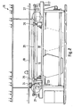
- Fig. 2 shows a schematic front view of a flat knitting machine 16 with a carrier 17 for at least one needle bed 18, with a spool board 19 and with a thread guide rail 20 extending above the needle bed 18 between two stands 21 and 22 arranged on the needle bed carrier.
- the machine carriage 23 is at the left end of the needle bed 18 is shown schematically with its bracket 24 spanning the thread guide rail.
- Two thread guides 25 and 26 are shown on the thread guide rail 20.
- the flat knitting machine 16 is provided for the threads, not shown, with guide bodies in the form of smooth wires 15, the thread guide rails between the two 20 supporting stands 21 and 22 are drawn parallel to the thread guide rails and underneath them and are held under tension by means of a tension spring 27 shown in the area of the stand 22.
- the wires 15 serve the threads as a guide body on their essentially horizontal feed path, which extends from the needle bed ends to the thread guides 25 or 26 movable along the needle beds 18.
- each thread guide has a thread guide arm 25.2 which extends from the thread guide carriage 25.1 down to the knitting area of the machine and which ends in a thread guide nut 25.3.
- a separate wire 15 is provided as a guide body for each thread. 4, the wires 15 are stretched below the thread guide rails 20 / 1-20 / 3 between the thread guide arms 25.2 of the individual thread guides 25, their position being predetermined by a special anchoring plate 28, which is only schematically indicated in FIGS. 3 and 4.
- the threads are placed in a few turns around the tensioning wires analogously to FIG. 1 and are guided away from the tensioning wire according to FIG. 3 into one of two lateral thread guide eyelets 29 of the thread guide arm 25.2 of the associated thread guide 25 and from there further to the thread guide nut 25.3.
- Threads act in a conventional manner, not shown, thread tensioning devices which also bring back the thread guided over a tensioned wire 15 as a thread guide when a thread guide 25 is reset.
- thread guide elements When using the thread guide elements on textile machines, other thread guide elements, such as thread guide eyelets, can generally be omitted in part.
Landscapes
- Engineering & Computer Science (AREA)
- Textile Engineering (AREA)
- Knitting Machines (AREA)
- Knitting Of Fabric (AREA)
Claims (3)
- Machine à tricoter rectiligne comportant pour les guide-fils (25) des rails (20/1 - 20/3) qui s'étendent au-dessus des plaques à aiguilles (18), ces guide-fils (25) pouvant être déplacés le long des plaques à aiguilles et comportant chacun un bras de guidage (25.2) pour amener un fil à tricoter (11) au voisinage des plaques à aiguilles (18), caractérisée en ce qu'à chaque rail (20/1 - 20/3) des guide-fils est associé un organe de guidage pour un fil à tricoter, constitué par un fil étiré tendu (15), lisse et sans arête vive, disposé parallèlement aux rails (20/1 - 20/3) des guide-fils, pour recevoir le fil à tricoter associé (11) en-roulé en hélice d'une manière connue sur ce fil métallique, sur au moins une spire.
- Machine à tricoter rectiligne selon la revendication 1, caractérisée en ce qu'elle comporte, au-dessous des rails (20/1-20/3) des guide-fils et dans les zones situées entre les différents bras (25.2) des guide-fils, plusieurs fils étirés (15) montés sous tension, constituant des organes de guidage écartés l'un de l'autre et s'étendant sur toute la longueur utile des plaques à aiguilles (18).
- Machine à tricoter rectiligne selon la revendication 1 ou 2, caractérisée en ce que les fils de guidage (15) sont fixés de manière rigide à l'endroit de l'une des extrémités d'une plaque à aiguilles (18), et fixés de manière élastique à l'endroit de l'autre extrémité de la plaque à aiguilles (18), avec interposition d'un ressort de tension (27).
Applications Claiming Priority (2)
| Application Number | Priority Date | Filing Date | Title |
|---|---|---|---|
| DE3641426 | 1986-12-04 | ||
| DE19863641426 DE3641426A1 (de) | 1986-12-04 | 1986-12-04 | Fadenfuehrungselement fuer textilmaschinen |
Publications (2)
| Publication Number | Publication Date |
|---|---|
| EP0275385A1 EP0275385A1 (fr) | 1988-07-27 |
| EP0275385B1 true EP0275385B1 (fr) | 1991-09-18 |
Family
ID=6315454
Family Applications (1)
| Application Number | Title | Priority Date | Filing Date |
|---|---|---|---|
| EP87116375A Expired - Lifetime EP0275385B1 (fr) | 1986-12-04 | 1987-11-06 | Guide-fil pour machines textiles |
Country Status (5)
| Country | Link |
|---|---|
| US (1) | US4819457A (fr) |
| EP (1) | EP0275385B1 (fr) |
| JP (1) | JPS63152443A (fr) |
| DE (1) | DE3641426A1 (fr) |
| ES (1) | ES2025612T3 (fr) |
Families Citing this family (9)
| Publication number | Priority date | Publication date | Assignee | Title |
|---|---|---|---|---|
| RU2314371C1 (ru) * | 2006-06-16 | 2008-01-10 | Московский государственный университет дизайна и технологий (МГУДТ) | Устройство для перемещения челноков трикотажной машины |
| CN102400274A (zh) * | 2010-09-14 | 2012-04-04 | 吴江华利针纺有限公司 | 引线装置 |
| CN102011266A (zh) * | 2010-12-29 | 2011-04-13 | 浙江维格针纺科技有限公司 | 强捻全涤罗马布的针织方法及针织机的纱线防结器 |
| CN102011257A (zh) * | 2010-12-29 | 2011-04-13 | 浙江维格针纺科技有限公司 | 强捻无弹汗布的针织方法及针织机的纱线防结器 |
| CN102953217A (zh) * | 2011-08-30 | 2013-03-06 | 吴江市洪盛纺织有限公司 | 导线架 |
| CH709607A1 (de) * | 2014-05-08 | 2015-11-13 | Rieter Ag Maschf | Verfahren zum Betrieb einer Textilmaschine zur Herstellung von Vorgarn, sowie Textilmaschine hierzu. |
| CN108754829A (zh) * | 2018-08-15 | 2018-11-06 | 湖北金犁劳保科技股份有限公司 | 一种手套编织机的主纱嘴 |
| CN110923929B (zh) * | 2019-12-31 | 2024-06-25 | 浙江越发科技集团有限公司 | 一种织袜机用纱嘴盘翻转防缠线装置 |
| CN113512810B (zh) * | 2021-07-13 | 2022-09-23 | 江南大学 | 一种纱线张力自调节的横机纱嘴装置 |
Family Cites Families (18)
| Publication number | Priority date | Publication date | Assignee | Title |
|---|---|---|---|---|
| US252018A (en) * | 1882-01-10 | Tension for grain-binders | ||
| US356377A (en) * | 1887-01-18 | Twine guide and tension device for harvesters | ||
| US1187912A (en) * | 1915-10-22 | 1916-06-20 | Lewis T Houghton | Tension device. |
| US1254761A (en) * | 1917-03-23 | 1918-01-29 | Elmira Knitting Mills | Guide and tension device for removing snarls, kinks, &c, from yarn or thread. |
| US1467443A (en) * | 1920-05-11 | 1923-09-11 | Willcox & Gibbs Sewing Machine | Tension-thread guide |
| US1596095A (en) * | 1925-10-08 | 1926-08-17 | David H Gehman | Thread-tension device |
| US1997709A (en) * | 1934-01-18 | 1935-04-16 | Mitchell Bissell Co | Thread tensioning device |
| US2528171A (en) * | 1949-05-21 | 1950-10-31 | Pehlivanian Anthony | Twist controller for thread |
| FR1173780A (fr) * | 1956-05-08 | 1959-03-02 | Procédé d'humectation de plantes, notamment du tabac, et appareil appliquant ce procédé | |
| CH365311A (de) * | 1957-10-15 | 1962-10-31 | Chr Mann Maschinenfabrik | Bewegliche Führungseinrichtung zum Wickeln von Kreuzspulen an Strecken oder Vorspinnmaschinen |
| DE6925374U (de) * | 1969-06-24 | 1969-11-27 | Dornier Gmbh Lindauer | Fadenbremse fuer textilmaschinen |
| DE2263569A1 (de) * | 1972-12-27 | 1974-07-04 | Rainer Kotte Textilmaschinenzu | Fadenbremse |
| IT1037710B (it) * | 1975-04-29 | 1979-11-20 | Zamark Srl | Dispositivo guidafili per macchine rettilinee da maglieria |
| DE7812210U1 (de) * | 1978-04-21 | 1978-08-10 | W. Schlaich Kg Jerseystrickerei, 7470 Albstadt | Fadenabzugsvorrichtung fuer eine rundstrickmaschine |
| US4186549A (en) * | 1978-05-30 | 1980-02-05 | Wwg Industries, Inc. | Packaging of self-twist yarns |
| JPS55161754A (en) * | 1979-05-28 | 1980-12-16 | Shigaken | Apparatus for preventing slackening of yarn due to inertia occurred upon starting and stopping of yarn and regulating tension of yarn |
| EP0092511A3 (fr) * | 1982-04-20 | 1986-10-15 | Maschinenfabrik Schärer AG | Procédé de formation d'une réserve de fil sans vrilles ainsi qu'une machine de bobinage |
| DE3617991A1 (de) * | 1986-05-28 | 1987-12-03 | Stoll & Co H | Fadenspannungs-reguliereinrichtung fuer strickmaschinen |
-
1986
- 1986-12-04 DE DE19863641426 patent/DE3641426A1/de not_active Withdrawn
-
1987
- 1987-11-06 ES ES198787116375T patent/ES2025612T3/es not_active Expired - Lifetime
- 1987-11-06 EP EP87116375A patent/EP0275385B1/fr not_active Expired - Lifetime
- 1987-11-18 US US07/122,222 patent/US4819457A/en not_active Expired - Fee Related
- 1987-12-03 JP JP62304708A patent/JPS63152443A/ja active Pending
Also Published As
| Publication number | Publication date |
|---|---|
| DE3641426A1 (de) | 1988-06-09 |
| ES2025612T3 (es) | 1992-04-01 |
| JPS63152443A (ja) | 1988-06-24 |
| US4819457A (en) | 1989-04-11 |
| EP0275385A1 (fr) | 1988-07-27 |
Similar Documents
| Publication | Publication Date | Title |
|---|---|---|
| EP0275385B1 (fr) | Guide-fil pour machines textiles | |
| DE2841210A1 (de) | Einrichtung zur ballonbegrenzung an einem spulengatter | |
| DE3316078A1 (de) | Fadenzufuhreinrichtung fuer strick- und wirkmaschinen | |
| DE3634578A1 (de) | Flachstrickmaschine mit garnspulenhaltern | |
| DE2939800A1 (de) | Spulentraeger fuer strickmaschinen | |
| EP0068120A1 (fr) | Râtelier pour machine de filature | |
| DE531867C (de) | Beweglicher Schussspulentraeger fuer Webstuehle mit feststehenden Schussspulen | |
| DE102011113286B4 (de) | Flachstrickmaschine | |
| DE741382C (de) | Spulengatter | |
| DE29810880U1 (de) | Frontrahmen für ein Wagengatter | |
| DE102011113573B4 (de) | Fadenführer für eine Flachstrickmaschine | |
| DE1535628B1 (de) | Rundwebmaschine | |
| AT156374B (de) | Vorrichtung zum Spannen von Schnüren aus Baumwolle, Garn, dünnem Draht od. dgl. über oder um Gebüsche, Beete und Baüme. | |
| EP0534896B1 (fr) | Dispositif et procédé pour limiter le ballon sur un cantre | |
| DE2012617A1 (de) | Spulengatter in Verbindung mit einer Rundstrickmaschine, die fur jede Faden zuführung eine Fadenliefervorrichtung hat | |
| DE1535628C (de) | Rundwebmaschine | |
| DE968590C (de) | Trockenvorrichtung fuer Garnstraehne | |
| AT328990B (de) | Scharmaschine | |
| DE2401581A1 (de) | Vielsystemige rundstrickmaschine | |
| DE500886C (de) | Spulengestell fuer Florwebstuehle | |
| AT118090B (de) | Zettelgatter. | |
| DE498682C (de) | Bremsanordnung fuer waagerecht liegende Mittelendspulen an Flecht- und Kloeppelmaschinen | |
| DE3220708A1 (de) | Flachstrickmaschine | |
| DE3344835A1 (de) | Liefervorrichtung fuer faeden, insbesondere zu webmaschinen | |
| DE1137824B (de) | Flachhandstrickgeraet |
Legal Events
| Date | Code | Title | Description |
|---|---|---|---|
| PUAI | Public reference made under article 153(3) epc to a published international application that has entered the european phase |
Free format text: ORIGINAL CODE: 0009012 |
|
| AK | Designated contracting states |
Kind code of ref document: A1 Designated state(s): CH ES FR GB IT LI |
|
| 17P | Request for examination filed |
Effective date: 19880909 |
|
| 17Q | First examination report despatched |
Effective date: 19900322 |
|
| GRAA | (expected) grant |
Free format text: ORIGINAL CODE: 0009210 |
|
| AK | Designated contracting states |
Kind code of ref document: B1 Designated state(s): CH ES FR GB IT LI |
|
| PGFP | Annual fee paid to national office [announced via postgrant information from national office to epo] |
Ref country code: CH Payment date: 19911007 Year of fee payment: 5 |
|
| ITF | It: translation for a ep patent filed | ||
| GBT | Gb: translation of ep patent filed (gb section 77(6)(a)/1977) | ||
| ET | Fr: translation filed | ||
| PGFP | Annual fee paid to national office [announced via postgrant information from national office to epo] |
Ref country code: GB Payment date: 19911025 Year of fee payment: 5 |
|
| PGFP | Annual fee paid to national office [announced via postgrant information from national office to epo] |
Ref country code: ES Payment date: 19911031 Year of fee payment: 5 |
|
| PGFP | Annual fee paid to national office [announced via postgrant information from national office to epo] |
Ref country code: FR Payment date: 19911114 Year of fee payment: 5 |
|
| REG | Reference to a national code |
Ref country code: ES Ref legal event code: FG2A Ref document number: 2025612 Country of ref document: ES Kind code of ref document: T3 |
|
| PLBE | No opposition filed within time limit |
Free format text: ORIGINAL CODE: 0009261 |
|
| STAA | Information on the status of an ep patent application or granted ep patent |
Free format text: STATUS: NO OPPOSITION FILED WITHIN TIME LIMIT |
|
| 26N | No opposition filed | ||
| PG25 | Lapsed in a contracting state [announced via postgrant information from national office to epo] |
Ref country code: GB Effective date: 19921106 |
|
| PG25 | Lapsed in a contracting state [announced via postgrant information from national office to epo] |
Ref country code: ES Free format text: LAPSE BECAUSE OF NON-PAYMENT OF DUE FEES Effective date: 19921107 |
|
| PG25 | Lapsed in a contracting state [announced via postgrant information from national office to epo] |
Ref country code: LI Effective date: 19921130 Ref country code: CH Effective date: 19921130 |
|
| GBPC | Gb: european patent ceased through non-payment of renewal fee |
Effective date: 19921106 |
|
| PG25 | Lapsed in a contracting state [announced via postgrant information from national office to epo] |
Ref country code: FR Effective date: 19930730 |
|
| REG | Reference to a national code |
Ref country code: CH Ref legal event code: PL |
|
| REG | Reference to a national code |
Ref country code: FR Ref legal event code: ST |
|
| REG | Reference to a national code |
Ref country code: ES Ref legal event code: FD2A Effective date: 19931214 |
|
| PG25 | Lapsed in a contracting state [announced via postgrant information from national office to epo] |
Ref country code: IT Free format text: LAPSE BECAUSE OF NON-PAYMENT OF DUE FEES;WARNING: LAPSES OF ITALIAN PATENTS WITH EFFECTIVE DATE BEFORE 2007 MAY HAVE OCCURRED AT ANY TIME BEFORE 2007. THE CORRECT EFFECTIVE DATE MAY BE DIFFERENT FROM THE ONE RECORDED. Effective date: 20051106 |