EP0275460A1 - Stosswellenkopf zum berührungslosen Zertrümmern von Konkrementen - Google Patents
Stosswellenkopf zum berührungslosen Zertrümmern von Konkrementen Download PDFInfo
- Publication number
- EP0275460A1 EP0275460A1 EP87118243A EP87118243A EP0275460A1 EP 0275460 A1 EP0275460 A1 EP 0275460A1 EP 87118243 A EP87118243 A EP 87118243A EP 87118243 A EP87118243 A EP 87118243A EP 0275460 A1 EP0275460 A1 EP 0275460A1
- Authority
- EP
- European Patent Office
- Prior art keywords
- shock wave
- lens arrangement
- shock
- stop
- patient
- Prior art date
- Legal status (The legal status is an assumption and is not a legal conclusion. Google has not performed a legal analysis and makes no representation as to the accuracy of the status listed.)
- Withdrawn
Links
- 230000035939 shock Effects 0.000 title claims abstract description 45
- 238000013467 fragmentation Methods 0.000 title 1
- 238000006062 fragmentation reaction Methods 0.000 title 1
- 210000003128 head Anatomy 0.000 description 12
- 238000010168 coupling process Methods 0.000 description 10
- 230000008878 coupling Effects 0.000 description 6
- 238000005859 coupling reaction Methods 0.000 description 6
- 239000012528 membrane Substances 0.000 description 5
- 210000003734 kidney Anatomy 0.000 description 3
- 239000012530 fluid Substances 0.000 description 2
- 239000007788 liquid Substances 0.000 description 2
- RYGMFSIKBFXOCR-UHFFFAOYSA-N Copper Chemical compound [Cu] RYGMFSIKBFXOCR-UHFFFAOYSA-N 0.000 description 1
- 230000009286 beneficial effect Effects 0.000 description 1
- 230000006835 compression Effects 0.000 description 1
- 238000007906 compression Methods 0.000 description 1
- 230000008602 contraction Effects 0.000 description 1
- 229910052802 copper Inorganic materials 0.000 description 1
- 239000010949 copper Substances 0.000 description 1
- 239000003814 drug Substances 0.000 description 1
- 230000005012 migration Effects 0.000 description 1
- 238000013508 migration Methods 0.000 description 1
- 210000001331 nose Anatomy 0.000 description 1
- 230000001960 triggered effect Effects 0.000 description 1
- XLYOFNOQVPJJNP-UHFFFAOYSA-N water Substances O XLYOFNOQVPJJNP-UHFFFAOYSA-N 0.000 description 1
Images
Classifications
-
- A—HUMAN NECESSITIES
- A61—MEDICAL OR VETERINARY SCIENCE; HYGIENE
- A61B—DIAGNOSIS; SURGERY; IDENTIFICATION
- A61B17/00—Surgical instruments, devices or methods
- A61B17/22—Implements for squeezing-off ulcers or the like on inner organs of the body; Implements for scraping-out cavities of body organs, e.g. bones; for invasive removal or destruction of calculus using mechanical vibrations; for removing obstructions in blood vessels, not otherwise provided for
- A61B17/225—Implements for squeezing-off ulcers or the like on inner organs of the body; Implements for scraping-out cavities of body organs, e.g. bones; for invasive removal or destruction of calculus using mechanical vibrations; for removing obstructions in blood vessels, not otherwise provided for for extracorporeal shock wave lithotripsy [ESWL], e.g. by using ultrasonic waves
- A61B17/2251—Implements for squeezing-off ulcers or the like on inner organs of the body; Implements for scraping-out cavities of body organs, e.g. bones; for invasive removal or destruction of calculus using mechanical vibrations; for removing obstructions in blood vessels, not otherwise provided for for extracorporeal shock wave lithotripsy [ESWL], e.g. by using ultrasonic waves characterised by coupling elements between the apparatus, e.g. shock wave apparatus or locating means, and the patient, e.g. details of bags, pressure control of bag on patient
-
- A—HUMAN NECESSITIES
- A61—MEDICAL OR VETERINARY SCIENCE; HYGIENE
- A61B—DIAGNOSIS; SURGERY; IDENTIFICATION
- A61B8/00—Diagnosis using ultrasonic, sonic or infrasonic waves
- A61B8/42—Details of probe positioning or probe attachment to the patient
- A61B8/4272—Details of probe positioning or probe attachment to the patient involving the acoustic interface between the transducer and the tissue
- A61B8/4281—Details of probe positioning or probe attachment to the patient involving the acoustic interface between the transducer and the tissue characterised by sound-transmitting media or devices for coupling the transducer to the tissue
-
- G—PHYSICS
- G10—MUSICAL INSTRUMENTS; ACOUSTICS
- G10K—SOUND-PRODUCING DEVICES; METHODS OR DEVICES FOR PROTECTING AGAINST, OR FOR DAMPING, NOISE OR OTHER ACOUSTIC WAVES IN GENERAL; ACOUSTICS NOT OTHERWISE PROVIDED FOR
- G10K11/00—Methods or devices for transmitting, conducting or directing sound in general; Methods or devices for protecting against, or for damping, noise or other acoustic waves in general
- G10K11/18—Methods or devices for transmitting, conducting or directing sound
- G10K11/26—Sound-focusing or directing, e.g. scanning
- G10K11/30—Sound-focusing or directing, e.g. scanning using refraction, e.g. acoustic lenses
-
- G—PHYSICS
- G10—MUSICAL INSTRUMENTS; ACOUSTICS
- G10K—SOUND-PRODUCING DEVICES; METHODS OR DEVICES FOR PROTECTING AGAINST, OR FOR DAMPING, NOISE OR OTHER ACOUSTIC WAVES IN GENERAL; ACOUSTICS NOT OTHERWISE PROVIDED FOR
- G10K9/00—Devices in which sound is produced by vibrating a diaphragm or analogous element, e.g. fog horns, vehicle hooters or buzzers
- G10K9/12—Devices in which sound is produced by vibrating a diaphragm or analogous element, e.g. fog horns, vehicle hooters or buzzers electrically operated
Definitions
- the invention relates to a shock wave head for contactlessly crushing a concrement located in the body of a living being with a shock wave generator which generates shock waves essentially in one plane and an associated lens arrangement which focuses the shock wave onto a focus area in the target area.
- Shock wave heads of this type are used in medicine, for example, to destroy stones in the kidney of humans. They are particularly beneficial because they avoid any intervention in the body. It is not necessary to operate surgically.
- Such a shock wave head is described in DE-OS 33 28 051, which has a shock wave tube consisting of a jacket, a flat coil and a copper membrane separated by an insulating film.
- An acoustic converging lens is arranged in the shock wave tube, which focuses the flat shock waves generated by the membrane at a focal point.
- the opening of the shock wave tube opposite the membrane is closed with a bag which, like the entire shock wave tube, is filled with a coupling medium.
- the shock wave tube is driven towards the patient until the concrement to be destroyed is in the focal point of the lens arrangement.
- the sack filled with the coupling fluid lies on the surface of the patient, so that it is ensured that the shock waves always run within the fluid.
- the invention is based on the object of designing a shock wave head of the type mentioned at the outset in such a way that the area of use of the shock wave head is expanded so that even obese patients can be treated.
- the object is achieved in that the lens arrangement rests adjustably on a stop such that it yields in the direction of the shock wave generator when the patient is pushed. This ensures that the patient is not moved during the coupling process, so that the concrement moves out of the focus area, but rather the lens arrangement yields, the focus area being moved back onto the shock wave head. However, the concretion is still within the focus range, so that it can be destroyed when shock waves are triggered.
- the lens arrangement is pressed against the stop by a spring.
- a migration of the concrement out of the focus area is prevented if the adjustment path for the lens arrangement is limited by a second stop and is a few centimeters. This travel corresponds essentially to the distance between the focus and the focus area.
- the emigration of the lens arrangement and the emigration of the concrement from the focus area can be displayed if the stops are provided with limit switches.
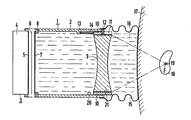
- a shock wave head 1 is shown with a jacket 2 filled with a liquid, for example water an opening through a shock wave generator 3, consisting of a coil carrier 4, a flat coil 5, an insulating film 6 and a membrane 7, which are held tightly pressed together by a retaining ring 8, is completed.
- a shock wave generator 3 consisting of a coil carrier 4, a flat coil 5, an insulating film 6 and a membrane 7, which are held tightly pressed together by a retaining ring 8, is completed.
- the flat coil 5, the insulating film 6 and the membrane 7 are each drawn at a distance from one another.
- the other opening of the jacket 2 of the shock wave head 1 is covered by a lens arrangement 9 with the function of an acoustic converging lens, which is held by a holder 10.
- the holder 10 has a plurality of grooves 11 on its circumference, which extend approximately from the center of the holder 10 away from the shock wave generator 3. Noses arranged on the jacket 2 engage as first stops 12 in the grooves 11.
- the holder 10 and the lens arrangement 9 are pressed against the first stops 12 by a plurality of compression springs 14 supported on further lugs 13.
- the jacket 2 of the shock wave head 1 and the lens arrangement 9 are covered by a bag 15 which is filled with coupling liquid 16. In the coupled state, the bag 15 lies against the skin of a patient 17.
- a concrement 19 arranged in a kidney 18 is located in the focal point F of the lens arrangement 9, so that it can be destroyed by shock waves generated by the shock wave generator 3.
- the lens arrangement 9 is moved against the force of the springs 14 in the direction of the shock wave generator 3. This can be done until the concretion 19 is still within the focus range. Since this focus area has a dimension of a few centimeters in the longitudinal direction of the shock wave head 1, the lens arrangement 9 can be displaced to the same extent without the contraction 19 moving out of the focus area. Therefore, on the circumference of the jacket 2 of the shock wave head 1 second stops 20 are provided, against which the holder 10 of the lens arrangement 9 abuts as a limitation of its travel.
- the lens arrangement 9 can be displaced with a fine adjustment 20 in the direction of the focus F relative to the holder 10 and thus to the jacket 2 of the shock wave head 1.
- Limit switches can be arranged on the stops 12 and 20, for example the limit switch on the first stop 12 is actuated when the lens arrangement 9 is displaced, so that the examiner can be shown that the lens arrangement 9 has moved out of its end position and thus at complete coupling the concrement is no longer within the focus, ie is within the maximum, but is only within the focus range. If, on the other hand, the lens arrangement 9 is moved against the second stop 20, on the one hand the coupling process can be interrupted immediately, while at the same time the examiner's monitor, for example, indicates that a coupling cannot take place since the concrement lies outside the focus range.
Landscapes
- Health & Medical Sciences (AREA)
- Life Sciences & Earth Sciences (AREA)
- Physics & Mathematics (AREA)
- Engineering & Computer Science (AREA)
- Surgery (AREA)
- Acoustics & Sound (AREA)
- Animal Behavior & Ethology (AREA)
- Public Health (AREA)
- Heart & Thoracic Surgery (AREA)
- Medical Informatics (AREA)
- Molecular Biology (AREA)
- Nuclear Medicine, Radiotherapy & Molecular Imaging (AREA)
- General Health & Medical Sciences (AREA)
- Biomedical Technology (AREA)
- Veterinary Medicine (AREA)
- Multimedia (AREA)
- Vascular Medicine (AREA)
- Biophysics (AREA)
- Pathology (AREA)
- Radiology & Medical Imaging (AREA)
- Orthopedic Medicine & Surgery (AREA)
- Surgical Instruments (AREA)
Abstract
Die Erfindung betrifft einen Stoßwellenkopf (1) zum berührungslosen Zertrümmern eines im Körper eines Lebewesens befindlichen Konkrementes (19) mit einem im wesentlichen in einer Ebene Stoßwellen erzeugenden Stoßwellengenerator (3) und einer ihm zugeordneten Linsenanordnung (9), die die Stoßwelle auf einen Fokusbereich im Zielgebiet fokussiert. Die Linsenanordnung (9) liegt verstellbar an einem Anschlag (12) derart an, daß sie bei Anstoßen des Patienten (17) in Richtung auf den Stoßwellengenerator (3) nachgibt.
Description
- Die Erfindung betrifft einen Stoßwellenkopf zum berührungslosen Zertrümmern eines im Körper eines Lebewesens befindlichen Konkrementes mit einem im wesentlichen in einer Ebene Stoßwellen erzeugenden Stoßwellengenerator und einer ihm zugeordneten Linsenanordnung, die die Stoßwelle auf einen Fokusbereich im Zielgebiet fokussiert. Stoßwellenköpfe dieser Art werden in der Medizin beispielsweise zum Zerstören von Steinen in der Niere des Menschen eingesetzt. Sie sind besonders vorteilhaft, da sie jeglichen Eingriff in den Körper vermeiden. Es ist nicht notwendig, operativ vorzugehen.
- In der DE-OS 33 28 051 ist ein derartiger Stoßwellenkopf beschrieben, der ein Stoßwellenrohr, bestehend aus einem Mantel, einer Flachspule und einer durch eine Isolierfolie getrennte Kupfermembran, aufweist. In dem Stoßwellenrohr ist eine akustische Sammellinse angeordnet, die die von der Membran erzeugten ebenen Stoßwellen in einem Brennpunkt fokussiert. Zur Ankopplung des Stoßwellenrohres an den Patienten ist die der Membran gegenüberliegende Öffnung des Stoßwellenrohres mit einem Sack abgeschlossen, der wie das gesamte Stoßwellenrohr mit einem Koppelmedium gefüllt ist. Zur Ankopplung wird das Stoßwellenrohr so lange auf den Patienten zugefahren, bis daß das zu zerstörende Konkrement sich im Brennpunkt der Linsenanordnung befindet. Hierbei legt sich der mit der Koppelflüssigkeit gefüllte Sack an der Oberfläche des Patienten an, so daß gewährleistet ist, daß die Stoßwellen immer innerhalb der Flüssigkeit verlaufen.
- Bei korpulenten Patienten tritt dabei das Problem auf, daß das zu zerstörende Konkrement so weit innerhalb des Körpers des Patienten liegt, daß der Fokusabstand der Linsenanordnung nicht mehr ausreicht. Dadurch berührt das Stoßwellenrohr bzw. die Linsenanordnung den Patienten und bei Fortsetzung des Ankoppelvorganges schieben sie den Patienten sogar zur Seite. Dadurch wird das Konkrement aus dem Fokus bewegt, so daß eine Behandlung nicht erfolgen kann.
- Die Erfindung geht von der Aufgabe aus, einen Stoßwellenkopf der eingangs genannten Art derart auszubilden, daß der Einsatzbereich des Stoßwellenkopfes erweitert wird, so daß auch korpulente Patienten behandelt werden können.
- Die Aufgabe wird erfindungsgemäß dadurch gelöst, daß die Linsenanordnung verstellbar an einem Anschlag derart anliegt, daß sie bei Anstoßen des Patienten in Richtung auf den Stoßwellengenerator nachgibt. Dadurch wird erreicht, daß während des Ankoppelvorganges nicht der Patient bewegt wird, so daß das Konkrement aus dem Fokusbereich herauswandert, sondern die Linsenanordnung nachgibt, wobei der Fokusbereich auf den Stoßwellenkopf zurückbewegt wird. Das Konkrement liegt aber weiterhin innerhalb des Fokusbereiches, so daß es bei Auslösen von Stoßwellen zerstört werden kann.
- Es hat sich als vorteilhaft erwiesen, wenn die Linsenanordnung durch eine Feder gegen den Anschlag gedrückt wird. Ein Auswandern des Konkrementes aus dem Fokusbereich wird verhindert, wenn der Stellweg für die Linsenanordnung durch einen zweiten Anschlag begrenzt ist und wenige Zentimeter beträgt. Dieser Stellweg entspricht im wesentlichen dem Abstand des Fokus zum Fokusbereich. Eine Anzeige des Auswanderns der Linsenanordnung sowie des Auswanderns des Konkrementes aus dem Fokusbereich kann erfolgen, wenn die Anschläge mit Endschaltern versehen sind.
- Die Erfindung ist nachfolgend anhand eines in der Zeichnung dargestellten Ausführungsbeispieles näher erläutert.
- In der Figur ist ein Stoßwellenkopf 1 mit einem mit einer Flüssigkeit, z.B. Wasser, gefüllten Mantel 2 dargestellt, dessen eine Öffnung durch einen Stoßwellengenerator 3, bestehend aus einem Spulenträger 4, einer Flachspule 5, einer Isolierfolie 6 und einer Membran 7, die durch einen Rückhaltering 8 eng aneinander gepreßt zusammengehalten werden, abgeschlossen wird. Aus Gründen einer besseren Übersicht sind die Flachspule 5, die Isolierfolie 6 und die Membran 7 jeweils im Abstand voneinander gezeichnet.
- Die andere Öffnung des Mantels 2 des Stoßwellenkopfes 1 wird durch eine Linsenanordnung 9 mit der Funktion einer akustischen Sammellinse abgedeckt, die von einer Halterung 10 gefaßt ist. Die Halterung 10 weist auf ihrem Umfang mehrere Nuten 11 auf, die sich etwa von der Mitte der Halterung 10 an von dem Stoßwellengenerator 3 weg erstrecken. In die Nuten 11 greifen am Mantel 2 angeordnete Nasen als erste Anschläge 12 ein. Durch mehrere an weiteren Nasen 13 sich abstützende Druckfedern 14 werden die Halterung 10 und die Linsenanordnung 9 gegen die ersten Anschläge 12 gepreßt. Der Mantel 2 des Stoßwellenkopfes 1 und die Linsenanordnung 9 werden von einem Sack 15 abgedeckt, der mit Koppelflüssigkeit 16 gefüllt ist. Im angekoppelten Zustand liegt der Sack 15 an der Haut eines Patienten 17 an. Dann befindet sich ein in einer Niere 18 angeordnetes Konkrement 19 in dem Brennpunkt F der Linsenanordnung 9, so daß es durch vom Stoßwellengenerator 3 erzeugte Stoßwellen zerstört kann.
- Ist nun der Patient 17 derart korpulent, daß der Abstand Haut zur Niere 18 und damit des Konkrementes 19 größer ist als der Fokusabstand, stößt die Oberfläche des Patienten 17 an der Linsenanordnung 9 an. Nun wird während des Ankoppelvorganges die Linsenanordnung 9 gegen die Kraft der Federn 14 in Richtung auf den Stoßwellengenerator 3 verschoben. Dies kann so lange erfolgen, bis daß das Konkrement 19 noch innerhalb des Fokusbereiches liegt. Da dieser Fokusbereich in Längsrichtung des Stoßwellenkopfes 1 eine Abmessung von einigen Zentimetern aufweist, läßt sich die Linsenanordnung 9 in gleichem Maße verschieben, ohne daß das Konktrement 19 aus dem Fokusbereich herauswandert. Deshalb sind auf dem Umfang des Mantels 2 des Stoßwellenkopfes 1 zweite Anschläge 20 vorgesehen, gegen die die Halterung 10 der Linsenanordnung 9 als Begrenzung ihres Stellweges stößt.
- Die Linsenanordnung 9 ist mit einer Feinregulierung 20 in Richtung auf den Fokus F relativ zur Halterung 10 und damit zum Mantel 2 des Stoßwellenkopfes 1 verschiebbar.
- An den Anschlägen 12 und 20 können Endschalter angeordnet sein, So wird beispielsweise der Endschalter an dem ersten Anschlag 12 bei Verschieben der Linsenanordnung 9 betätigt, so daß dadurch der Untersuchungsperson angezeigt werden kann, daß sich die Linsenanordnung 9 aus ihrer Endlage bewegt hat und damit bei vollständiger Ankopplung das Konkrement sich nicht mehr innerhalb des Fokus, d.h. innerhalb des Maximums, befindet, sondern nur noch innerhalb des Fokusbereiches liegt. Wird die Linsenanordnung 9 dagegen gegen den zweiten Anschlag 20 bewegt, so kann zum einen der Ankoppelvorgang sofort unterbrochen werden, während gleichzeitig beispielsweise auf dem Monitor der Untersuchungsperson angezeigt wird, daß eine Ankopplung nicht erfolgen kann, da das Konkrement außerhalb des Fokusbereiches liegt.
Claims (4)
1. Stoßwellenkopf (1) zum berührungslosen Zertrümmern eines im Körper eines Lebewesens befindlichen Konkrementes (19) mit einem im wesentlichen in einer Ebene Stoßwellen erzeugenden Stoßwellengenerator (3) und einer ihm zugeordneten Linsenanordnung (9), die die Stoßwelle auf einen Fokusbereich im Zielgebiet fokussiert, dadurch gekennzeichnet, daß die Linsenanordnung (9) verstellbar an einem Anschlag (12) derart anliegt, daß sie bei Anstoßen des Patienten (17) in Richtung auf den Stoßwellengenerator (3) nachgibt.
2. Stoßwellenkopf (1) nach Anspruch 1, dadurch gekennzeichnet, daß die Linsenanordnung (9) durch eine Feder (14) gegen den Anschlag (12) gedrückt wird.
3. Stoßwellenkopf nach Anspruch 1 oder 2, dadurch gekennzeichnet, daß der Stellweg für die Linsenanordnung (9) durch einen zweiten Anschlag (20) begrenzt ist und wenige Zentimeter beträgt.
4. Stoßwellenkopf nach Anspruch 3, dadurch gekennzeichnet, daß die Anschläge (12, 20) mit Endschaltern versehen sind.
Applications Claiming Priority (2)
| Application Number | Priority Date | Filing Date | Title |
|---|---|---|---|
| DE3643971 | 1986-12-22 | ||
| DE3643971 | 1986-12-22 |
Publications (1)
| Publication Number | Publication Date |
|---|---|
| EP0275460A1 true EP0275460A1 (de) | 1988-07-27 |
Family
ID=6316923
Family Applications (1)
| Application Number | Title | Priority Date | Filing Date |
|---|---|---|---|
| EP87118243A Withdrawn EP0275460A1 (de) | 1986-12-22 | 1987-12-09 | Stosswellenkopf zum berührungslosen Zertrümmern von Konkrementen |
Country Status (2)
| Country | Link |
|---|---|
| US (1) | US4838248A (de) |
| EP (1) | EP0275460A1 (de) |
Cited By (1)
| Publication number | Priority date | Publication date | Assignee | Title |
|---|---|---|---|---|
| DE102005056905A1 (de) * | 2005-11-29 | 2007-05-31 | Switech Medical Ag | Stosswellenerzeuger mit tiefenausgedehntem Fokalgebiet |
Families Citing this family (4)
| Publication number | Priority date | Publication date | Assignee | Title |
|---|---|---|---|---|
| DE4136004C1 (de) * | 1991-10-31 | 1993-01-28 | Siemens Ag, 8000 Muenchen, De | |
| CN104887280A (zh) * | 2015-06-23 | 2015-09-09 | 苏州市瑞晟医疗器械有限公司 | 一种透镜可调的骨科治疗机的波源装置 |
| TWI653026B (zh) | 2018-01-08 | 2019-03-11 | 寶健科技股份有限公司 | 可變焦之震波頭 |
| JP2024011846A (ja) * | 2022-07-15 | 2024-01-25 | 株式会社アドバンテスト | 超音波測定装置、方法、プログラム、記録媒体 |
Citations (5)
| Publication number | Priority date | Publication date | Assignee | Title |
|---|---|---|---|---|
| US3800276A (en) * | 1960-09-02 | 1974-03-26 | Us Navy | Acoustic image conversion tube |
| US4194510A (en) * | 1978-06-15 | 1980-03-25 | Second Foundation, Inc. | Ultrasonic focusing system |
| WO1982004157A1 (en) * | 1981-05-23 | 1982-11-25 | Lierke Ernst Guenter | Installation for transmiting and receiving focused ultrasonic waves |
| EP0133665A2 (de) * | 1983-08-03 | 1985-03-06 | Siemens Aktiengesellschaft | Einrichtung zum berührungslosen Zertrümmern von Konkrementen |
| DE3444421A1 (de) * | 1984-12-04 | 1986-06-05 | Dornier System Gmbh, 7990 Friedrichshafen | Einrichtung zur ankopplung eines behandlungsgeraets an den menschlichen koerper, insbesondere zur beruehrungsfreien zerstoerung von konkrementen im menschlichen koerper |
Family Cites Families (2)
| Publication number | Priority date | Publication date | Assignee | Title |
|---|---|---|---|---|
| FR2477723A1 (fr) * | 1980-03-07 | 1981-09-11 | Cgr Ultrasonic | Sonde d'echographie ultrasonore a lentille acoustique et echographe comportant une telle sonde |
| US4476873A (en) * | 1982-09-03 | 1984-10-16 | Medtronic, Inc. | Ultrasound scanning system for skeletal imaging |
-
1987
- 1987-12-09 EP EP87118243A patent/EP0275460A1/de not_active Withdrawn
- 1987-12-11 US US07/133,283 patent/US4838248A/en not_active Expired - Fee Related
Patent Citations (5)
| Publication number | Priority date | Publication date | Assignee | Title |
|---|---|---|---|---|
| US3800276A (en) * | 1960-09-02 | 1974-03-26 | Us Navy | Acoustic image conversion tube |
| US4194510A (en) * | 1978-06-15 | 1980-03-25 | Second Foundation, Inc. | Ultrasonic focusing system |
| WO1982004157A1 (en) * | 1981-05-23 | 1982-11-25 | Lierke Ernst Guenter | Installation for transmiting and receiving focused ultrasonic waves |
| EP0133665A2 (de) * | 1983-08-03 | 1985-03-06 | Siemens Aktiengesellschaft | Einrichtung zum berührungslosen Zertrümmern von Konkrementen |
| DE3444421A1 (de) * | 1984-12-04 | 1986-06-05 | Dornier System Gmbh, 7990 Friedrichshafen | Einrichtung zur ankopplung eines behandlungsgeraets an den menschlichen koerper, insbesondere zur beruehrungsfreien zerstoerung von konkrementen im menschlichen koerper |
Cited By (1)
| Publication number | Priority date | Publication date | Assignee | Title |
|---|---|---|---|---|
| DE102005056905A1 (de) * | 2005-11-29 | 2007-05-31 | Switech Medical Ag | Stosswellenerzeuger mit tiefenausgedehntem Fokalgebiet |
Also Published As
| Publication number | Publication date |
|---|---|
| US4838248A (en) | 1989-06-13 |
Similar Documents
| Publication | Publication Date | Title |
|---|---|---|
| DE4212809C2 (de) | Therapieeinrichtung zur Behandlung eines Lebewesens mit fokussierten akustischen Wellen | |
| DE69009666T2 (de) | Ultraschallperkussionsgerät. | |
| DE3443295C2 (de) | ||
| EP0301360B1 (de) | Stosswellenquelle mit zentralem Ultraschall-Ortungssystem | |
| EP0196353A2 (de) | Vorrichtung zur Vermeidung oder Minderung von Schmerzen bei der extracorporalen Lithotripsie | |
| DE4136004C1 (de) | ||
| DE3312014A1 (de) | Einrichtung zur beruehrungsfreien zertruemmerung von konkrementen im koerper von lebewesen | |
| EP0369177B1 (de) | Vorrichtung zur Erzeugung von fokussierten akustischen Druckwellen | |
| EP0327917A1 (de) | Stosswellenquelle zum berührungslosen Zertrümmern von Konkrementen im Körper eines Lebewesens | |
| DE4110102A1 (de) | Elektromagnetische druckimpulsquelle | |
| EP0254104B1 (de) | Stosswellengenerator zur Erzeugung eines akustischen Stosswellenimpulses | |
| DE3608877C2 (de) | ||
| EP0133946A2 (de) | Einrichtung zum berührungslosen Zertrümmern von Konkrementen | |
| EP0396860B1 (de) | Ortungskinematik für einen Lithotripter | |
| DE3328039C2 (de) | Einrichtung zum beruehrungslosen zertruemmern eines im koerper eines lebewesens befindlichen konkrements | |
| DE3840077A1 (de) | Lithotriptor | |
| EP0273256A1 (de) | Vorrichtung zum berührungslosen Zertrümmern von Konkrementen | |
| EP0355178B1 (de) | Einrichtung zum berührungslosen Zertrümmern von Konkrementen im Körper eines Lebewesens | |
| DE19548000C1 (de) | Vorrichtung zur Ortung von Konkrementen im Körper eines Patienten | |
| EP0811354B1 (de) | Vorrichtung zur Ortung und Zertrümmerung von Konkrementen | |
| EP0275460A1 (de) | Stosswellenkopf zum berührungslosen Zertrümmern von Konkrementen | |
| EP0400196A1 (de) | Stosswellenkopf für die Zertrümmerung von Konkrementen | |
| EP0243650B1 (de) | Stosswellenquelle mit verbesserter Fokuszone | |
| EP0227929A1 (de) | Wasserkissen zur Verwendung bei der berührungsfreien Lithotripsie | |
| EP0167670B1 (de) | Einrichtung zum Zertrümmern von im Körper eines Lebewesens befindlichen Konkrementen |
Legal Events
| Date | Code | Title | Description |
|---|---|---|---|
| PUAI | Public reference made under article 153(3) epc to a published international application that has entered the european phase |
Free format text: ORIGINAL CODE: 0009012 |
|
| AK | Designated contracting states |
Kind code of ref document: A1 Designated state(s): DE FR GB NL |
|
| 17P | Request for examination filed |
Effective date: 19880830 |
|
| 17Q | First examination report despatched |
Effective date: 19910321 |
|
| STAA | Information on the status of an ep patent application or granted ep patent |
Free format text: STATUS: THE APPLICATION IS DEEMED TO BE WITHDRAWN |
|
| 18D | Application deemed to be withdrawn |
Effective date: 19910801 |
|
| RIN1 | Information on inventor provided before grant (corrected) |
Inventor name: GRASSER, FRANZ, DIPL.-ING. (FH) |