EP0275535A1 - Prothèse de valve cardiaque - Google Patents
Prothèse de valve cardiaque Download PDFInfo
- Publication number
- EP0275535A1 EP0275535A1 EP87119076A EP87119076A EP0275535A1 EP 0275535 A1 EP0275535 A1 EP 0275535A1 EP 87119076 A EP87119076 A EP 87119076A EP 87119076 A EP87119076 A EP 87119076A EP 0275535 A1 EP0275535 A1 EP 0275535A1
- Authority
- EP
- European Patent Office
- Prior art keywords
- tongue
- valve body
- heart valve
- valve prosthesis
- prosthesis according
- Prior art date
- Legal status (The legal status is an assumption and is not a legal conclusion. Google has not performed a legal analysis and makes no representation as to the accuracy of the status listed.)
- Withdrawn
Links
- 210000003709 heart valve Anatomy 0.000 title claims abstract description 38
- 230000036772 blood pressure Effects 0.000 claims abstract description 8
- 210000004369 blood Anatomy 0.000 claims abstract description 7
- 239000008280 blood Substances 0.000 claims abstract description 7
- 230000008859 change Effects 0.000 claims abstract description 3
- 239000000463 material Substances 0.000 claims description 13
- 210000001765 aortic valve Anatomy 0.000 claims description 11
- 230000017531 blood circulation Effects 0.000 claims description 11
- 210000004351 coronary vessel Anatomy 0.000 claims description 8
- 230000002093 peripheral effect Effects 0.000 claims description 8
- 230000000903 blocking effect Effects 0.000 claims description 7
- 230000007423 decrease Effects 0.000 claims description 6
- 238000000137 annealing Methods 0.000 claims description 2
- 239000004033 plastic Substances 0.000 claims description 2
- 229920003023 plastic Polymers 0.000 claims description 2
- 210000000709 aorta Anatomy 0.000 description 8
- 230000003205 diastolic effect Effects 0.000 description 7
- 210000000601 blood cell Anatomy 0.000 description 5
- 230000006378 damage Effects 0.000 description 4
- 238000004026 adhesive bonding Methods 0.000 description 2
- 230000015271 coagulation Effects 0.000 description 2
- 238000005345 coagulation Methods 0.000 description 2
- 230000004048 modification Effects 0.000 description 2
- 238000012986 modification Methods 0.000 description 2
- 238000003466 welding Methods 0.000 description 2
- 241000283690 Bos taurus Species 0.000 description 1
- VGGSQFUCUMXWEO-UHFFFAOYSA-N Ethene Chemical compound C=C VGGSQFUCUMXWEO-UHFFFAOYSA-N 0.000 description 1
- 239000005977 Ethylene Substances 0.000 description 1
- 239000004743 Polypropylene Substances 0.000 description 1
- 239000004809 Teflon Substances 0.000 description 1
- 229920006362 Teflon® Polymers 0.000 description 1
- 238000005452 bending Methods 0.000 description 1
- 239000012620 biological material Substances 0.000 description 1
- 238000010276 construction Methods 0.000 description 1
- 230000007547 defect Effects 0.000 description 1
- 230000001419 dependent effect Effects 0.000 description 1
- 230000035487 diastolic blood pressure Effects 0.000 description 1
- 230000000694 effects Effects 0.000 description 1
- 230000002349 favourable effect Effects 0.000 description 1
- 239000007943 implant Substances 0.000 description 1
- 238000002513 implantation Methods 0.000 description 1
- 210000005240 left ventricle Anatomy 0.000 description 1
- 238000000034 method Methods 0.000 description 1
- 238000000465 moulding Methods 0.000 description 1
- 210000000056 organ Anatomy 0.000 description 1
- 210000003516 pericardium Anatomy 0.000 description 1
- -1 polypropylene Polymers 0.000 description 1
- 229920001155 polypropylene Polymers 0.000 description 1
- 229920002635 polyurethane Polymers 0.000 description 1
- 239000004814 polyurethane Substances 0.000 description 1
- 230000008569 process Effects 0.000 description 1
- 230000004044 response Effects 0.000 description 1
- 230000000284 resting effect Effects 0.000 description 1
- 230000035488 systolic blood pressure Effects 0.000 description 1
- 230000002861 ventricular Effects 0.000 description 1
Images


Classifications
-
- A—HUMAN NECESSITIES
- A61—MEDICAL OR VETERINARY SCIENCE; HYGIENE
- A61F—FILTERS IMPLANTABLE INTO BLOOD VESSELS; PROSTHESES; DEVICES PROVIDING PATENCY TO, OR PREVENTING COLLAPSING OF, TUBULAR STRUCTURES OF THE BODY, e.g. STENTS; ORTHOPAEDIC, NURSING OR CONTRACEPTIVE DEVICES; FOMENTATION; TREATMENT OR PROTECTION OF EYES OR EARS; BANDAGES, DRESSINGS OR ABSORBENT PADS; FIRST-AID KITS
- A61F2/00—Filters implantable into blood vessels; Prostheses, i.e. artificial substitutes or replacements for parts of the body; Appliances for connecting them with the body; Devices providing patency to, or preventing collapsing of, tubular structures of the body, e.g. stents
- A61F2/02—Prostheses implantable into the body
- A61F2/24—Heart valves ; Vascular valves, e.g. venous valves; Heart implants, e.g. passive devices for improving the function of the native valve or the heart muscle; Transmyocardial revascularisation [TMR] devices; Valves implantable in the body
- A61F2/2412—Heart valves ; Vascular valves, e.g. venous valves; Heart implants, e.g. passive devices for improving the function of the native valve or the heart muscle; Transmyocardial revascularisation [TMR] devices; Valves implantable in the body with soft flexible valve members, e.g. tissue valves shaped like natural valves
-
- A—HUMAN NECESSITIES
- A61—MEDICAL OR VETERINARY SCIENCE; HYGIENE
- A61F—FILTERS IMPLANTABLE INTO BLOOD VESSELS; PROSTHESES; DEVICES PROVIDING PATENCY TO, OR PREVENTING COLLAPSING OF, TUBULAR STRUCTURES OF THE BODY, e.g. STENTS; ORTHOPAEDIC, NURSING OR CONTRACEPTIVE DEVICES; FOMENTATION; TREATMENT OR PROTECTION OF EYES OR EARS; BANDAGES, DRESSINGS OR ABSORBENT PADS; FIRST-AID KITS
- A61F2/00—Filters implantable into blood vessels; Prostheses, i.e. artificial substitutes or replacements for parts of the body; Appliances for connecting them with the body; Devices providing patency to, or preventing collapsing of, tubular structures of the body, e.g. stents
- A61F2/02—Prostheses implantable into the body
- A61F2/24—Heart valves ; Vascular valves, e.g. venous valves; Heart implants, e.g. passive devices for improving the function of the native valve or the heart muscle; Transmyocardial revascularisation [TMR] devices; Valves implantable in the body
- A61F2/2412—Heart valves ; Vascular valves, e.g. venous valves; Heart implants, e.g. passive devices for improving the function of the native valve or the heart muscle; Transmyocardial revascularisation [TMR] devices; Valves implantable in the body with soft flexible valve members, e.g. tissue valves shaped like natural valves
- A61F2/2418—Scaffolds therefor, e.g. support stents
-
- A—HUMAN NECESSITIES
- A61—MEDICAL OR VETERINARY SCIENCE; HYGIENE
- A61F—FILTERS IMPLANTABLE INTO BLOOD VESSELS; PROSTHESES; DEVICES PROVIDING PATENCY TO, OR PREVENTING COLLAPSING OF, TUBULAR STRUCTURES OF THE BODY, e.g. STENTS; ORTHOPAEDIC, NURSING OR CONTRACEPTIVE DEVICES; FOMENTATION; TREATMENT OR PROTECTION OF EYES OR EARS; BANDAGES, DRESSINGS OR ABSORBENT PADS; FIRST-AID KITS
- A61F2/00—Filters implantable into blood vessels; Prostheses, i.e. artificial substitutes or replacements for parts of the body; Appliances for connecting them with the body; Devices providing patency to, or preventing collapsing of, tubular structures of the body, e.g. stents
- A61F2/02—Prostheses implantable into the body
- A61F2/04—Hollow or tubular parts of organs, e.g. bladders, tracheae, bronchi or bile ducts
- A61F2/06—Blood vessels
- A61F2002/061—Blood vessels provided with means for allowing access to secondary lumens
Definitions
- the invention relates to a heart valve prosthesis in the form of a two-way valve, with an essentially tubular valve body that defines at least one first passage opening, and a valve element connected to it, which can be moved under the change in direction of the blood pressure between a blocking position closing the passage opening and an opening position releasing it and allows the blood to reach a second passage opening in the blocking position.
- Heart valves are already in the prior art theses, especially for the aortic valve, are known in a variety of designs and configurations. Older proposals were directed to the use of ball or lid valve valves as a heart valve prosthesis, but due to the inevitable flow processes, the mechanical stress on the blood cells increases, which promotes their damage or destruction and thus the risk of coagulation (thrombi) brings itself.
- Lid flap prostheses are known, for example, from DE-PS 15 41 286 and DE-PS 28 46 299, but lead to the strong mechanical stress of the blood cells mentioned. From DE-OS 27 00 531 a pocket flap modeled after the natural aortic valve is known; However, this has such a complicated structure that it does not meet the requirements for the function and service life of a heart valve prosthesis, in particular an aortic valve prosthesis.
- the inventor of the present application has proposed a heart valve prosthesis of the type mentioned at the outset to overcome the problems not solved in the prior art; this is in the DE-PS 34 26 300 disclosed.
- the structure and function of this known heart valve prosthesis will be explained in more detail in the following description of the figures.
- the generic heart valve prosthesis consists of two tubular channel pieces, each of which forms a flow channel and whose walls (or a common wall) are arranged and deformable by blood pressure in such a way that the first channel is under the systolic, the second channel under the diastolic pressure essentially opens while the other channel is closed.
- the space required for this known prosthesis particularly with regard to its longitudinal extent, is still considerable, which makes implantation more difficult.
- the distal tubular channel piece has to perform a pivoting movement which takes place under bending of the wall (s) connecting the flow channels. This can only be done by overcoming inertia and elastic restoring forces, which make the response times of the prosthesis relatively long when the direction of the blood pressure changes.
- the object of the invention is to improve a heart valve prosthesis of the type mentioned at the outset in such a way that a valve function which is as resistant as possible and with a reduced overall length of the prosthesis is made possible without giving up the favorable flow properties and long service life.
- valve element is formed by a flexible tongue which is only connected at one end region to a peripheral partial region of the valve body.
- the invention separates from the basic concept of the generic state of the art, namely to design each flow channel as a tubular element and to open and close the channels by deforming their walls.
- a single, tubular valve body is provided, which can be very short; the first passage opening defined by the valve body is no longer blocked or released by wall deformation of the valve body, but by a flexible tongue.
- This tongue can consist of a thin, small sheet of material, so that it can be moved much more easily and quickly than the closed, much larger hose that the generic type the prior art forms the diastolic flow channel.
- the blood flow which derives from the second flow channel in the generic state of the art, must be guided specifically to its destination.
- This function takes over the tongue according to the invention by allowing the blood flow to reach the second passage opening in its blocking position.
- the heart valve prosthesis according to the invention has at least the same lifespan as the generic prosthesis. It no longer opposes the blood cells to the baffle surface, so that the advantages already achieved by the generic state of the art are also realized in the invention.
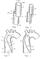
- the known heart valve prosthesis 1 ⁇ of the inventor shown in FIGS. 1 to 4 consists of two tube elements 2, 3, which are connected to one another in the axial direction and connected by a common wall 4.
- the first hose element 2 forms a first passage opening 5
- the second hose element 3 forms a second passage opening 6.
- this prosthesis is implanted, for example, as an aortic valve prosthesis in the ascending aorta, the first tube element 2 extending over the ostia of the coronary arteries, one of which is indicated at 40 in FIGS. 3 and 4.
- the second tube element 3 preferably bent in the longitudinal direction protrudes into the aortic arc.
- the implanted prosthesis is connected to the aortic wall 7 by support sutures 8, 9.
- the stroke volume of the left ventricle enters the first tube element 2 in the direction of the arrow and leaves it through the first passage opening 5.
- the common wall 4 of the tube elements 2, 3 is pivoted out of the flow path, so that the flow channel formed by the second hose element 3 and in particular its Passage 6 is closed.
- the diastolic phase (FIG. 4)
- the blood flows in the opposite direction, but this time through the flow channel which has returned to the open state at the end of the expulsion period and which the second tube element 3 forms, as the arrow in FIG. 4 indicates.
- the second tube element 3 expands and closes the passage opening 5 of the first tube element 2.
- the diastolic blood therefore does not flow to the ventricle, but rather through the second passage opening 6 to the ostium 40.
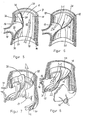
- the heart valve prosthesis 1 shown comprises a valve body 10 which is designed as a short, tube-like element.
- the outer shape of the valve body 10 is adapted to the aortic wall contour.
- An opening 16 is provided in the tube wall of the valve body 10 and, when the heart valve prosthesis 1 is implanted as an aortic valve prosthesis, lies opposite the ostium 40 of a coronary artery.
- a second corresponding opening can be provided opposite the ostium of the other coronary artery (not shown); instead of the opening 16 can also extend in the circumferential direction of the valve body 10 over both ostia.
- the wall area of the valve body 10 between the opening 16 and the ring area 14 merges in one piece in a connecting area 23 into a tongue 20, which is thereby connected at its one end area 22 to a peripheral partial area of the valve body 10.
- the material thickness of the tongue 20 decreases, starting from the end region 22 of the tongue 20 which merges into the connecting region 23 up to an essentially straight front edge 28 at the free end 24 of the tongue.
- the front edge 28 merges approximately at right angles into side edges 32 (only one shown) of the tongue 20, so that the tongue 20 is approximately rectangular overall.
- the inner circumferential wall of the valve body 10 forms a contact surface 18 against which the free end 24 of the tongue 20 can rest.
- the free end 24 of the tongue 20 is pivoted out of the direction of flow and lies in front of the opening 16.
- the systolic blood can therefore pass through a first Flow through opening 12, which is bounded by the proximal main surface of the tongue 20 and the inner peripheral wall of the valve body 10. An unwanted entry from systolic blood through the opening 16 into the ostium 40 is prevented by the tongue 20 closing the opening 16.
- the blood pressure direction reverses. Due to the elasticity of the tongue material, at the end of the systolic phase, the tongue 20 has been pivoted back from the position shown in FIG. 5 towards the first passage opening 12. If the diastolic blood flow now flows against it, the tongue 20, as illustrated in FIG. 6, closes over the first passage opening 12 and thereby seals the aorta in the ventricular direction, the free end 24 resting against the contact surface 18. The distal major surface of the tongue 20 directs the diastolic blood flow to the opening 16 so that it can enter the ostium of the respective coronary artery.
- the modification shown in FIGS. 7 and 8 of the embodiment just described has a fastening ring (annealing ring) 15 which surrounds the proximal end of the valve body 10.
- the fastening ring 15 is used analogously to the ring region 14 described above for the attachment of a support suture 30 which fixes the prosthesis to the aortic wall.
- the tongue 20 is fastened with an end region 22 to the inside of the proximal end of the valve body 10, for example by welding, gluing or the like.
- the contact surface 18 extends at This embodiment between the distal end of the valve body 10 and an inwardly projecting annular shoulder 19, which serves as a seat for the free end 24 of the tongue 20.
- the width of the tongue in the connection area 23 is so large that the tongue 20 can cover the opening 16 (or two separate openings 16) communicating with the ostia 40, 42.
- the tongue 20 can be fastened to the inner wall of the valve body 10 in addition to the opening 16, for example by welding, gluing or integral molding. This improves the covering function of the tongue 20 compared to the opening 16.
- the tongue 20 can also be designed such that its material thickness decreases from the longitudinal center to the side edges 32.
- FIGS. 9 and 10 illustrate the shape of the tongue 20 and in particular show the decrease in the material thickness in the direction of the front edge 28 and the side edges 32.
- these dimensions will be chosen depending on the material to be used so that a sufficiently large and easy mobility of the free end 24 of the tongue 20 on the one hand, but on the other hand a sufficient elastic restoring effect is obtained so that the tongue 20 moves quickly and completely under the blood pressure into the opening or blocking position, but not in at the point of reversal between systole and diastole the last position remains, but is brought back into a middle position, from which it can then move into the desired new position.
- FIG. 11 to 13 show a second embodiment of the heart valve prosthesis according to the invention. While in the first embodiment described above the tongue 20 is practically completely inside the valve body 10, in this second embodiment a tongue 60 is provided which is arranged at the distal end of a valve body 50.
- the valve body 50 is also a short, tube-like element in this embodiment. At the proximal (in FIGS. 11 and 12: lower) end, it carries a fastening ring 56 on the outside, by means of which the prosthesis can be sutured to the aortic wall 7 (FIG. 12). As with the first embodiment described with reference to FIGS. 5 to 10, this fastening ring 56 is, however, optional; the prosthesis can also be fixed directly to the aortic wall 7 without a ring area or fastening ring.
- the tongue 60 emerges in one piece from a peripheral partial region of the uninterrupted valve body wall. It has a free end which ends in a front edge 58 and can, with this free end, lie sealingly over the first passage opening which is formed by the distal opening of the valve body 50. As in the first embodiment, the material thickness of the tongue 60 decreases towards the front edge 58. Along the longitudinal center 62 of the tongue 60 there is an elevation 52 which can be formed in this area by a correspondingly larger material thickness. The elevation 52 becomes flatter and narrower in the direction of the front edge 58 in order not to impair the mobility of the free end of the tongue 60.
- the outer circumferential surface of the valve body 50 is provided with two channel-like depressions 54 which lead to the distal main surface of the tongue 60 facing away from the valve body 50 and each open onto this main side of the tongue 60 on one side of the elevation 52.
- the recesses 54 extend from the tongue 60 around the circumference of the valve body 50, as illustrated in FIGS. 11 and 12.
- this embodiment is implanted as an aortic valve prosthesis, as shown in FIG. 12, then the depressions 54 lead to the ostia of the coronary arteries; this is shown for an ostium 40 in FIG.
- Fig. 13 shows this position of the prosthesis as seen from the ventricle; the depressions 54 are not shown.
- the prostheses according to the invention are designed in such a way that they do not oppose the blood flow, in particular the systolic blood flow, with any sharp edges. This not only prevents turbulence, but also mechanical damage to blood cells.
- the prostheses according to the invention can be produced from suitable materials that are compatible as an implant and have the necessary mechanical properties.
- Polyurethane, polypropylene or polytetrafluor are suitable as biocompatible plastic materials ethylene (Teflon). Instead, it can also be considered to use suitable biomaterials, for example bovine pericardium.
- prosthesis according to the invention is not limited to use as an aortic valve prosthesis; rather, the prosthesis can also be used to replace organ parts other than the aortic valve, possibly with a corresponding modification in the structure.
- the prosthesis does not have to be designed so that the tongue lies substantially against the valve body in the blocking position;
- a system on the vessel wall (aortic wall) also fulfills the function sought according to the invention.
Landscapes
- Health & Medical Sciences (AREA)
- Engineering & Computer Science (AREA)
- Biomedical Technology (AREA)
- Cardiology (AREA)
- Oral & Maxillofacial Surgery (AREA)
- Transplantation (AREA)
- Heart & Thoracic Surgery (AREA)
- Vascular Medicine (AREA)
- Life Sciences & Earth Sciences (AREA)
- Animal Behavior & Ethology (AREA)
- General Health & Medical Sciences (AREA)
- Public Health (AREA)
- Veterinary Medicine (AREA)
- Prostheses (AREA)
Applications Claiming Priority (2)
| Application Number | Priority Date | Filing Date | Title |
|---|---|---|---|
| US06/946,385 US4787901A (en) | 1984-07-17 | 1986-12-23 | Two-way acting valve and cardiac valve prosthesis |
| US946385 | 1992-09-17 |
Publications (1)
| Publication Number | Publication Date |
|---|---|
| EP0275535A1 true EP0275535A1 (fr) | 1988-07-27 |
Family
ID=25484393
Family Applications (1)
| Application Number | Title | Priority Date | Filing Date |
|---|---|---|---|
| EP87119076A Withdrawn EP0275535A1 (fr) | 1986-12-23 | 1987-12-22 | Prothèse de valve cardiaque |
Country Status (1)
| Country | Link |
|---|---|
| EP (1) | EP0275535A1 (fr) |
Cited By (11)
| Publication number | Priority date | Publication date | Assignee | Title |
|---|---|---|---|---|
| EP0515324A1 (fr) * | 1991-05-24 | 1992-11-25 | SORIN BIOMEDICA CARDIO S.p.A. | Prothèse de valvule cardiaque, notamment pour remplacement de la valvule aortique |
| WO1996029954A1 (fr) * | 1995-03-28 | 1996-10-03 | Norman Godin | Prothese pour s'opposer au reflux gastrique dans l'×sophage |
| US6126686A (en) * | 1996-12-10 | 2000-10-03 | Purdue Research Foundation | Artificial vascular valves |
| US6302917B1 (en) | 1998-08-31 | 2001-10-16 | Wilson-Cook Medical Incorporated | Anti-reflux esophageal prosthesis |
| US6746489B2 (en) | 1998-08-31 | 2004-06-08 | Wilson-Cook Medical Incorporated | Prosthesis having a sleeve valve |
| US7118600B2 (en) | 1998-08-31 | 2006-10-10 | Wilson-Cook Medical, Inc. | Prosthesis having a sleeve valve |
| US8221505B2 (en) | 2007-02-22 | 2012-07-17 | Cook Medical Technologies Llc | Prosthesis having a sleeve valve |
| US9308360B2 (en) | 2007-08-23 | 2016-04-12 | Direct Flow Medical, Inc. | Translumenally implantable heart valve with formed in place support |
| US9445897B2 (en) | 2012-05-01 | 2016-09-20 | Direct Flow Medical, Inc. | Prosthetic implant delivery device with introducer catheter |
| US9603708B2 (en) | 2010-05-19 | 2017-03-28 | Dfm, Llc | Low crossing profile delivery catheter for cardiovascular prosthetic implant |
| CN115177859A (zh) * | 2022-07-28 | 2022-10-14 | 北京悦唯医疗科技有限责任公司 | 球囊导管 |
Citations (2)
| Publication number | Priority date | Publication date | Assignee | Title |
|---|---|---|---|---|
| DE3426300A1 (de) * | 1984-07-17 | 1986-01-30 | Doguhan Dr.med. 6000 Frankfurt Baykut | Zweiwegeventil und seine verwendung als herzklappenprothese |
| EP0183904A2 (fr) * | 1984-12-07 | 1986-06-11 | Shelhigh, Inc. | Prothèse des valvules du coeur |
-
1987
- 1987-12-22 EP EP87119076A patent/EP0275535A1/fr not_active Withdrawn
Patent Citations (2)
| Publication number | Priority date | Publication date | Assignee | Title |
|---|---|---|---|---|
| DE3426300A1 (de) * | 1984-07-17 | 1986-01-30 | Doguhan Dr.med. 6000 Frankfurt Baykut | Zweiwegeventil und seine verwendung als herzklappenprothese |
| EP0183904A2 (fr) * | 1984-12-07 | 1986-06-11 | Shelhigh, Inc. | Prothèse des valvules du coeur |
Cited By (17)
| Publication number | Priority date | Publication date | Assignee | Title |
|---|---|---|---|---|
| EP0515324A1 (fr) * | 1991-05-24 | 1992-11-25 | SORIN BIOMEDICA CARDIO S.p.A. | Prothèse de valvule cardiaque, notamment pour remplacement de la valvule aortique |
| US5713953A (en) * | 1991-05-24 | 1998-02-03 | Sorin Biomedica Cardio S.P.A. | Cardiac valve prosthesis particularly for replacement of the aortic valve |
| WO1996029954A1 (fr) * | 1995-03-28 | 1996-10-03 | Norman Godin | Prothese pour s'opposer au reflux gastrique dans l'×sophage |
| US5861036A (en) * | 1995-03-28 | 1999-01-19 | Biomedix S.A. Switzerland | Medical prosthesis for preventing gastric reflux in the esophagus |
| US6126686A (en) * | 1996-12-10 | 2000-10-03 | Purdue Research Foundation | Artificial vascular valves |
| US6302917B1 (en) | 1998-08-31 | 2001-10-16 | Wilson-Cook Medical Incorporated | Anti-reflux esophageal prosthesis |
| US6746489B2 (en) | 1998-08-31 | 2004-06-08 | Wilson-Cook Medical Incorporated | Prosthesis having a sleeve valve |
| US7118600B2 (en) | 1998-08-31 | 2006-10-10 | Wilson-Cook Medical, Inc. | Prosthesis having a sleeve valve |
| US8221505B2 (en) | 2007-02-22 | 2012-07-17 | Cook Medical Technologies Llc | Prosthesis having a sleeve valve |
| US9308360B2 (en) | 2007-08-23 | 2016-04-12 | Direct Flow Medical, Inc. | Translumenally implantable heart valve with formed in place support |
| US10130463B2 (en) | 2007-08-23 | 2018-11-20 | Dfm, Llc | Translumenally implantable heart valve with formed in place support |
| US9603708B2 (en) | 2010-05-19 | 2017-03-28 | Dfm, Llc | Low crossing profile delivery catheter for cardiovascular prosthetic implant |
| US10478299B2 (en) | 2010-05-19 | 2019-11-19 | Dfm, Llc | Low crossing profile delivery catheter for cardiovascular prosthetic implant |
| US9445897B2 (en) | 2012-05-01 | 2016-09-20 | Direct Flow Medical, Inc. | Prosthetic implant delivery device with introducer catheter |
| US12403007B2 (en) | 2012-05-01 | 2025-09-02 | Speyside Medical Llc | Prosthetic implant delivery device with introducer catheter |
| CN115177859A (zh) * | 2022-07-28 | 2022-10-14 | 北京悦唯医疗科技有限责任公司 | 球囊导管 |
| CN115177859B (zh) * | 2022-07-28 | 2025-08-29 | 北京悦唯医疗科技有限责任公司 | 球囊导管 |
Similar Documents
| Publication | Publication Date | Title |
|---|---|---|
| DE2815756C3 (de) | Prothetisches Verschlußelement zum Ersatz der Klappen im menschlichen Herzen | |
| DE69215960T2 (de) | Herzklappenprothese, insbesondere zum Ersatz der Aortenklappe | |
| EP0143246B1 (fr) | Prothèse de valvule cardiaque | |
| DE69106095T2 (de) | Bioprosthetische herzklappe mit elastischen verbindungsstellen. | |
| DE69403482T2 (de) | Ringprothese für herzchirurgie | |
| DE2742681C3 (de) | Prothetisches Verschlußelement zum Ersatz der Mitral- und Tricuspldalklappe im menschlichen Herzen | |
| DE3426300A1 (de) | Zweiwegeventil und seine verwendung als herzklappenprothese | |
| DE69721550T2 (de) | Herzklappenprothese mit nahtteil aus nicht-gleichförmiger radialer breite | |
| DE60017791T2 (de) | Gefässventilklappe | |
| DE69330003T2 (de) | Perkutan implantierbares Ventil für Blutgefässe | |
| DE69523251T2 (de) | Gestützte herzklappenprothese | |
| DE3608435C2 (fr) | ||
| DE2819089C2 (fr) | ||
| DE3701702C1 (de) | Herzklappenprothese | |
| DE60011132T2 (de) | Prothese zum kontrollieren der flussrichtung in einem körpergefäss | |
| DE69127593T2 (de) | Künstliche Herzklappe | |
| WO1997049355A1 (fr) | Valvule mitrale prothetique | |
| DE102007049404A1 (de) | Implantat zur Anordnung in einem Blutzirkulationskanal | |
| DE102017202159A1 (de) | Biologische Transkatheterklappe | |
| DE2440522A1 (de) | Implantat fuer die befaehigung eines erwachsenen mannes zur erlangung von penis- erektionen | |
| EP3672527B1 (fr) | Prothèse valvulaire implantable | |
| EP0355323B1 (fr) | Valvule cardiaque prothétique | |
| DE3409005A1 (de) | Prothese zum ersatz der aortenklappen | |
| DE10162821A1 (de) | Gefässprothese, insbesondere zum Ersatz von herznahen Bereichen der Aorta | |
| EP1455688A1 (fr) | Prothese de vaisseau sanguin con ue en particulier pour remplacer des zones aortiques proches du coeur |
Legal Events
| Date | Code | Title | Description |
|---|---|---|---|
| PUAI | Public reference made under article 153(3) epc to a published international application that has entered the european phase |
Free format text: ORIGINAL CODE: 0009012 |
|
| AK | Designated contracting states |
Kind code of ref document: A1 Designated state(s): AT BE CH DE ES FR GB GR IT LI LU NL SE |
|
| 17P | Request for examination filed |
Effective date: 19890126 |
|
| 17Q | First examination report despatched |
Effective date: 19900921 |
|
| STAA | Information on the status of an ep patent application or granted ep patent |
Free format text: STATUS: THE APPLICATION IS DEEMED TO BE WITHDRAWN |
|
| 18D | Application deemed to be withdrawn |
Effective date: 19911203 |