EP0275601A1 - Appareil de projection et dispositif de visualisation associé - Google Patents
Appareil de projection et dispositif de visualisation associé Download PDFInfo
- Publication number
- EP0275601A1 EP0275601A1 EP87202582A EP87202582A EP0275601A1 EP 0275601 A1 EP0275601 A1 EP 0275601A1 EP 87202582 A EP87202582 A EP 87202582A EP 87202582 A EP87202582 A EP 87202582A EP 0275601 A1 EP0275601 A1 EP 0275601A1
- Authority
- EP
- European Patent Office
- Prior art keywords
- filter
- radiation
- display device
- layers
- layer
- Prior art date
- Legal status (The legal status is an assumption and is not a legal conclusion. Google has not performed a legal analysis and makes no representation as to the accuracy of the status listed.)
- Granted
Links
- 230000005855 radiation Effects 0.000 claims abstract description 86
- 239000000463 material Substances 0.000 claims abstract description 64
- 230000003595 spectral effect Effects 0.000 claims abstract description 22
- 238000005286 illumination Methods 0.000 claims abstract description 21
- OAICVXFJPJFONN-UHFFFAOYSA-N Phosphorus Chemical compound [P] OAICVXFJPJFONN-UHFFFAOYSA-N 0.000 claims description 31
- 230000003287 optical effect Effects 0.000 claims description 23
- 230000005540 biological transmission Effects 0.000 claims description 15
- VYPSYNLAJGMNEJ-UHFFFAOYSA-N Silicium dioxide Chemical compound O=[Si]=O VYPSYNLAJGMNEJ-UHFFFAOYSA-N 0.000 claims description 14
- 229910052814 silicon oxide Inorganic materials 0.000 claims description 10
- RVTZCBVAJQQJTK-UHFFFAOYSA-N oxygen(2-);zirconium(4+) Chemical compound [O-2].[O-2].[Zr+4] RVTZCBVAJQQJTK-UHFFFAOYSA-N 0.000 claims description 8
- 239000000758 substrate Substances 0.000 claims description 8
- 229910001928 zirconium oxide Inorganic materials 0.000 claims description 8
- 239000002178 crystalline material Substances 0.000 claims description 5
- 230000005284 excitation Effects 0.000 claims description 5
- 229910052751 metal Inorganic materials 0.000 claims description 5
- 239000002184 metal Substances 0.000 claims description 5
- GWEVSGVZZGPLCZ-UHFFFAOYSA-N Titan oxide Chemical compound O=[Ti]=O GWEVSGVZZGPLCZ-UHFFFAOYSA-N 0.000 claims description 4
- 230000008859 change Effects 0.000 claims description 4
- CJNBYAVZURUTKZ-UHFFFAOYSA-N hafnium(iv) oxide Chemical compound O=[Hf]=O CJNBYAVZURUTKZ-UHFFFAOYSA-N 0.000 claims description 4
- 239000007788 liquid Substances 0.000 claims description 4
- ORUIBWPALBXDOA-UHFFFAOYSA-L magnesium fluoride Chemical compound [F-].[F-].[Mg+2] ORUIBWPALBXDOA-UHFFFAOYSA-L 0.000 claims description 4
- QSHDDOUJBYECFT-UHFFFAOYSA-N mercury Chemical compound [Hg] QSHDDOUJBYECFT-UHFFFAOYSA-N 0.000 claims description 4
- 229910052753 mercury Inorganic materials 0.000 claims description 4
- URLJKFSTXLNXLG-UHFFFAOYSA-N niobium(5+);oxygen(2-) Chemical compound [O-2].[O-2].[O-2].[O-2].[O-2].[Nb+5].[Nb+5] URLJKFSTXLNXLG-UHFFFAOYSA-N 0.000 claims description 4
- BPUBBGLMJRNUCC-UHFFFAOYSA-N oxygen(2-);tantalum(5+) Chemical compound [O-2].[O-2].[O-2].[O-2].[O-2].[Ta+5].[Ta+5] BPUBBGLMJRNUCC-UHFFFAOYSA-N 0.000 claims description 4
- 229910052793 cadmium Inorganic materials 0.000 claims description 3
- 239000003086 colorant Substances 0.000 claims description 3
- 229910052709 silver Inorganic materials 0.000 claims description 3
- 229920000136 polysorbate Polymers 0.000 claims description 2
- 239000003989 dielectric material Substances 0.000 claims 3
- 230000005693 optoelectronics Effects 0.000 abstract 1
- 239000004973 liquid crystal related substance Substances 0.000 description 9
- 230000008901 benefit Effects 0.000 description 3
- 230000001419 dependent effect Effects 0.000 description 3
- 230000000694 effects Effects 0.000 description 3
- 239000011521 glass Substances 0.000 description 3
- 230000004048 modification Effects 0.000 description 3
- 238000012986 modification Methods 0.000 description 3
- 239000010453 quartz Substances 0.000 description 3
- 229910052844 willemite Inorganic materials 0.000 description 3
- CBQYNPHHHJTCJS-UHFFFAOYSA-N Alline Chemical compound C1=CC=C2C3(O)CCN(C)C3NC2=C1 CBQYNPHHHJTCJS-UHFFFAOYSA-N 0.000 description 2
- 230000004075 alteration Effects 0.000 description 2
- 229910052802 copper Inorganic materials 0.000 description 2
- 239000006185 dispersion Substances 0.000 description 2
- 238000001914 filtration Methods 0.000 description 2
- 230000006872 improvement Effects 0.000 description 2
- 239000000203 mixture Substances 0.000 description 2
- 230000004044 response Effects 0.000 description 2
- 102000006830 Luminescent Proteins Human genes 0.000 description 1
- 108010047357 Luminescent Proteins Proteins 0.000 description 1
- 238000010521 absorption reaction Methods 0.000 description 1
- 230000009471 action Effects 0.000 description 1
- 210000004027 cell Anatomy 0.000 description 1
- 239000002826 coolant Substances 0.000 description 1
- 238000001816 cooling Methods 0.000 description 1
- 238000012937 correction Methods 0.000 description 1
- 210000002858 crystal cell Anatomy 0.000 description 1
- 238000000151 deposition Methods 0.000 description 1
- 238000010894 electron beam technology Methods 0.000 description 1
- 238000000295 emission spectrum Methods 0.000 description 1
- 239000005262 ferroelectric liquid crystals (FLCs) Substances 0.000 description 1
- 125000001475 halogen functional group Chemical group 0.000 description 1
- 239000011159 matrix material Substances 0.000 description 1
- 230000035945 sensitivity Effects 0.000 description 1
- 238000001228 spectrum Methods 0.000 description 1
- 238000004544 sputter deposition Methods 0.000 description 1
- XOLBLPGZBRYERU-UHFFFAOYSA-N tin dioxide Chemical compound O=[Sn]=O XOLBLPGZBRYERU-UHFFFAOYSA-N 0.000 description 1
- 229910001887 tin oxide Inorganic materials 0.000 description 1
- OGIDPMRJRNCKJF-UHFFFAOYSA-N titanium oxide Inorganic materials [Ti]=O OGIDPMRJRNCKJF-UHFFFAOYSA-N 0.000 description 1
- 229910052725 zinc Inorganic materials 0.000 description 1
Images

Classifications
-
- H—ELECTRICITY
- H04—ELECTRIC COMMUNICATION TECHNIQUE
- H04N—PICTORIAL COMMUNICATION, e.g. TELEVISION
- H04N9/00—Details of colour television systems
- H04N9/12—Picture reproducers
- H04N9/31—Projection devices for colour picture display, e.g. using electronic spatial light modulators [ESLM]
-
- G—PHYSICS
- G02—OPTICS
- G02F—OPTICAL DEVICES OR ARRANGEMENTS FOR THE CONTROL OF LIGHT BY MODIFICATION OF THE OPTICAL PROPERTIES OF THE MEDIA OF THE ELEMENTS INVOLVED THEREIN; NON-LINEAR OPTICS; FREQUENCY-CHANGING OF LIGHT; OPTICAL LOGIC ELEMENTS; OPTICAL ANALOGUE/DIGITAL CONVERTERS
- G02F1/00—Devices or arrangements for the control of the intensity, colour, phase, polarisation or direction of light arriving from an independent light source, e.g. switching, gating or modulating; Non-linear optics
- G02F1/01—Devices or arrangements for the control of the intensity, colour, phase, polarisation or direction of light arriving from an independent light source, e.g. switching, gating or modulating; Non-linear optics for the control of the intensity, phase, polarisation or colour
- G02F1/13—Devices or arrangements for the control of the intensity, colour, phase, polarisation or direction of light arriving from an independent light source, e.g. switching, gating or modulating; Non-linear optics for the control of the intensity, phase, polarisation or colour based on liquid crystals, e.g. single liquid crystal display cells
- G02F1/133—Constructional arrangements; Operation of liquid crystal cells; Circuit arrangements
- G02F1/1333—Constructional arrangements; Manufacturing methods
- G02F1/1335—Structural association of cells with optical devices, e.g. polarisers or reflectors
- G02F1/1336—Illuminating devices
- G02F1/133617—Illumination with ultraviolet light; Luminescent elements or materials associated to the cell
-
- H—ELECTRICITY
- H04—ELECTRIC COMMUNICATION TECHNIQUE
- H04N—PICTORIAL COMMUNICATION, e.g. TELEVISION
- H04N3/00—Scanning details of television systems; Combination thereof with generation of supply voltages
- H04N3/10—Scanning details of television systems; Combination thereof with generation of supply voltages by means not exclusively optical-mechanical
- H04N3/12—Scanning details of television systems; Combination thereof with generation of supply voltages by means not exclusively optical-mechanical by switched stationary formation of lamps, photocells or light relays
- H04N3/127—Scanning details of television systems; Combination thereof with generation of supply voltages by means not exclusively optical-mechanical by switched stationary formation of lamps, photocells or light relays using liquid crystals
-
- H—ELECTRICITY
- H04—ELECTRIC COMMUNICATION TECHNIQUE
- H04N—PICTORIAL COMMUNICATION, e.g. TELEVISION
- H04N9/00—Details of colour television systems
- H04N9/12—Picture reproducers
- H04N9/31—Projection devices for colour picture display, e.g. using electronic spatial light modulators [ESLM]
- H04N9/3102—Projection devices for colour picture display, e.g. using electronic spatial light modulators [ESLM] using two-dimensional electronic spatial light modulators
- H04N9/3105—Projection devices for colour picture display, e.g. using electronic spatial light modulators [ESLM] using two-dimensional electronic spatial light modulators for displaying all colours simultaneously, e.g. by using two or more electronic spatial light modulators
Definitions
- the invention relates to a projection device comprising a projection screen, at least one radiation source and at least one monochrome display device for operation in the transmission mode, with an electro-optical means between two parallel substrates provided with drive means to cause the electro-optical means to change its transmission state at least locally and to define a pattern in the electro-optical means which is projected via projection means onto the projection screen.
- the electro-optical means may be one of the many liquid crystalline materials, but alternatively the display device may be an electroscopic display.
- the invention also relates to a display device and an illumination source which can be used in such a projection device, but which are alternatively usable for other applications.
- a problem in such a projection device is the use of the white light source which has a wide spectrum as regards the emitted radiation. In the optical set-up of the system this gives rise to an incomplete split-up into the three primary colours (red, green, blue) and to chromatic aberration in the image on the projection screen.
- a projection device is characterized in that the display device is provided with a layer of material luminescing in one colour, which material can be excited by radiation from the radiation source and in that a first interference filter is arranged between the radiation source and the layer of luminescent material, which filter substantially completely passes radiation suitable for excitation and substantially completely reflects radiation generated in the luminescent material, whilst a second interference filter is arranged on the other side of the layer of luminescent material, which filter has a high transmission for light of the desired spectral characteristic (spectral lines or spectral band) and in which the reflection considerably increases for light rays of the desired spectral characteristic extending at an angle of more than 20 to 35° to the normal on the filter.
- a device has a high light output ( > 85 %) and passes light of the desired spectral lines at small angles, whereas light of unwanted spectral lines cannot emanate at all due to the action of the second filter.
- the device comprises three monochrome display devices, each with a material luminescing in a different colour and each with an optical axis extending perpendicularly from the centre of the display portion of the display device, the optical axes of the three display devices being co-planar, the axes of the first and second display devices coinciding and the axis of the third display device constituting the principle axis of the projection device, said axis being perpendicular to the two coincident axes, and in that the device also comprises dichroic prisms reflecting the image of the first display device and the image of the second display device in the direction of the principle axis and away from the third display device and passing the image of the third display device in the direction of the principle axis.
- the device may alternatively comprise two plane dichroic reflecting mirrors intersecting each other and extending perpendicularly to the said plane and through the point of intersection of the axes, each mirror extending at an angle of 45° to the principle axis, the first mirror reflecting the image of the first display device and the second mirror reflecting the image of the second display device in the direction of the principle axis and away from the third display device.
- the first interference filter is used to prevent loss of light due to emission and dispersion in the luminescent layer in the direction of the radiation source, as has been further described in the Application no. PHN 11.998 filed simultaneously.
- the first interference filter and the luminescent layer viewed from the radiation source, may be arranged both in front of and behind the liquid crystalline material; in the latter case the liquid crystalline material serves as a switch for the radiation emitted by the source.
- luminescent material in combination with the second interference filter, has the advantage that (sub)pictures are obtained which are substantially entirely monochromatic so that there is little chromatic aberration and no lens corrections are required.
- dichroic prisms or mirrors arranged at an angle of 45° function very satisfactorily for this more monochromatic light.
- the second interference filter By providing the second interference filter a limited transmission angle is obtained for the desired spectral lines or band, while in addition the reflection in the direction of the luminescent layer considerably increases for light rays extending at an angle of more than 20 to 35 to the normal on the filter. At larger angles up to 90° there is substantially no transmission.
- the light reflected at these larger angles is dispersed by the luminescent layer. A part thereof returns at smaller angles and can still contribute to the light output; by arranging such a second interference filter a light output gain by a factor of 1.8 to 2.4 is achieved in this application..
- the second interference filter preferably has a number of layers (at least 9, but preferably 14) consisting alternately of a material having a high refractive index and of a material having a low refractive index, each with an optical thickness n . d in which n is the refractive index of the material of the layer and d is the thickness, which optical thickness n . d is between 0.2 ⁇ f and 0.3 ⁇ f in which ⁇ f is equal to p ⁇ ⁇ , in which ⁇ is the central wavelength of the relevant display device and p is a number between 1.16 and 1.30.
- the average optical thickness is 0.25 ⁇ f and ⁇ f is the central wavelength of the filter.
- the filter thus comprises exclusively or substantially exclusively layers having an optical thickness of approximately 0.25 ⁇ f .
- the layer thickness es in the filter according to the invention are thus chosen to be such that at a desired wavelength the reflection starts to increase considerably for light rays from the luminescent material which extend at an angle of more than 20 to 35° to the normal on the filter.
- the broad reflection band ensures that light rays extending at angles of more than 20 to 35° are reflected as much as possible and after dispersion in the luminescent material again get a chance of emanating in the forward direction, that is to say within an angle of at most 20 to 35° to the normal on the filter. Consequently, a maximum light output in the forward direction is produced, which is at least 60% larger than without use of the filter.
- the broad reflection band ensures that the halo effect is greatly reduced and that light emanates to a smaller extent at large angles.
- the optical thickness n.d of the layers of the filter is preferably not equal for all layers but varies between 0.2 ⁇ f and 0.27 ⁇ f . Due to this variation in thickness a flatter response characteristic of the filter is obtained . Since the response characteristic of the filter is wavelength-dependent, a combination of the relevant phosphor and an adapted filter provides the possibility of improving the colour point of the light rays which traverse the filter within an angle of 20 to 35° to the normal
- the first interference filter it is possible to choose a so-called "all-dielectric" multilayer filter comprising at least 6 but preferably 9 to 30 layers alternately having a high and a low refractive index. A sufficiently broad reflection bandwidth for one colour can be obtained with this number of layers.
- An advantage is that there is no absorption in the filter, provided that the materials chosen are transparent both to the exciting and to the generated radiation.
- a "metal-dielectric" filter may alternatively be chosen comprising only 3 to 5 layers of alternately a metal layer and a layer of dielectric material.
- Various choices are also possible for the phosphors.
- a radiation source based on predominantly long-wave UV-radiation for example 360-380 nanometers, for example a ZnS: Ag - blue phosphor; (Zn, Cd)S:Cu, Ag - green phosphor; Y2DtS: Eu - red phosphor are suitable.
- the associated emission wavelengths are readily suitable for the maximum sensitivity of each of the three colour receptors of the eye; this renders an eminent colour display possible.
- the invention also relates to a display device which is particularly but not exclusively suitable for use in the projection device described.
- a display device which is particularly but not exclusively suitable for use in the projection device described.
- Such a device may also be used, for example in monochrome display devices (data graphic displays).
- the invention also relates to an illumination source as is used in such devices.
- This illumination source having a radiation source in a holder bounded by at least a flat wall is characterized in that the wall is at least locally provided with a layer of luminescent material which can be excited by radiation from the radiation source and in that a first interference filter is arranged between the radiation source and the layer of luminescent material, which filter substantially completely passes radiation suitable for excitation and substantially completely reflects radiation generated in the luminescent material, whilst a second filter is arranged on the other side of the layer of luminescent material, which filter has a high transmission for light of the desired spectral lines or spectral band which is emitted by the luminescent layer at small angles to the normal on the filter and in which the reflection considerably increases for light rays of the said spectral lines or band which extend at an angle of more than 20 to 35° to the normal on the filter.
- a light source can be obtained which emits light of a desired colour (determined by spectral lines or band) at a limited angle.
- a light source may also be used in, for example direct-vision display devices in which a small viewing angle is sufficient.
- Figure 1 shows diagrammatically a projection device 1 having three radiation sources 2, mirrors 43 and three monochrome display devices 3 in which a red (3R), a green (3G) and a blue (3B) picture are generated.
- the three pictures are imaged via dichroic prisms 4 and a lens 5 on a screen 6 on which they register in such a manner that an overall colour picture is obtained.
- the axes of the display devices 3B and 3R coincide and are perpendicular to the axis 11 of the display device 3G wnich also constitutes the principle axis of the projection device.
- Tne pictures from the display devices 3B and 3R may not only be imaged on the screen 6 by means of prisms 4 but also by means of two plane dichroic mirrors which intersect each other and each of which extends at an angle of 45° to the axis 11 and which extend perpendicularly to the plane of the axes of the dsplay device through the point of intersection of the axes.
- the device 1 comprises a radiation sources 2 which emits radiation 10 (in this embodiment UV radiation).
- This radiation which is shown as a single line is actually incident through a wide angle range and has such a wavelength that it can excite phosphors present in the display devices 3 according to the invention.
- the radiation sources 2, for example high-pressure mercury lamps, need not be entirely identical.
- the gas filling of the lamps may be adapted in such a manner that the emission spectrum satisfactorily suits the associated phosphor layer. Different wavelengths for the different phosphors may be desired, for example UV radiation for the blue phosphor,, blue light for the green phospnor and blue or blue-green light for the red phosphor.
- All sources 2 may also emit long-wave UV radiation with the following phosphors being satisfactory: ZnS:Ag (Bleu). (Zn,Cd)S: Cu, Ag (green) and Y2O2S: Eu (red).
- FIG. 2 shows diagrammatically one of the display devices 3, in this embodiment a liquid crystal display device having a liquid crystal 12 as an electro-optical medium which is present between two parallel transparent substrates 13, 14 of, for example, glass.
- Transparent strip-shaped electrodes 15, 16,in this embodiment of tin oxide, defining a matrix of switching points are present on these substrates.
- the electrodes are coated with a layer of orienting material 17 of, for example, silicon oxide.
- the display device also comprises a polariser 19 and an analyser 20 while the assembly is secured to a support 21. This support must be transparent to radiation from the radiation source 2 and will be made of, for example quartz when using short-wave UV radiation.
- the display device 3 has a phosphor layer 18 which, dependent on the type of phosphor used, emits, for example red, green or blue light if the layer 18 is excited by radiation 10 suitable for this purpose, and a first interference filter 22 is arranged in the radiation path in front of the phosphor layer 18, which filter substantially completely passes the radiation 10 and substantially completely reflects the light generated in the phosphor layer. It is achieved thereby that light generated in the phosphor layer 18 which would otherwise leave the phosphor layer 18 on the side of the filter 22 is reflected by this layer 22 and thus contributes to the overall light output. In this way a greater brightness (2 to 3 times) is obtained than if the interference filter 22 were not provided.
- the device comprises a second interference filter 23 having such a composition that the colour generated in the phosphor layer 18 is passed at a limited transmission angle.
- a second interference filter 23 having such a composition that the colour generated in the phosphor layer 18 is passed at a limited transmission angle.
- liquid crys t alline material 12 Various materials may be chosen for the liquid crys t alline material 12. For example, use can be made of the so-called twisted nematic materials, but materials whose effect is based on birefringence such as, for example described in EP 0,131,216 (270°-twist) or in DE 34,31,871 (180°-twist) or ferro-electric liquid crystals are alternatively suitable.
- the invention may be alternatively used for other electro-optical display devices used in the transmission mode such as , for example (dry) electroscopic displays.
- Figure 3 shows diagrammatically a modification of the device of Figure 2 in which the display device is divided into a part 3 A accommodating the liquid crystal 12 and the electrodes 15, 16 with the associated intermediate layers and a part 3 B in which, for example UV radiation 10 which is incident at a wide angle range is converted into visible substantially monochromatic radiation 10 ⁇ with a small angle range in the direction of propagation.
- the part 3 B accommodates the fluorescent layer 18 and the interference filters 22, 23 between supports 21 and 28.
- the polarisers 19 and 19 ⁇ may optionally be provided on the part 3 A or on the part 3 B .
- Tne structure shown has the advantage that heat generated in the fluorescent layer 18 is less likely to produce a higher temperature in the liquid crystal. This effect can be enhanced by utilizing the gap 29 between the parts 3 A and 3 B for cooling purposes, for example by means of a suitably transparent coolant.
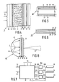
- FIG 4 shows a further embodiment of a device according to the invention.
- the liquid crystal material 12 now functions as a switch for the exciting radiation, for example UV radiation, and the phosphor pattern 18 is on the other side.
- the liquid crystal material used and the wave-length may be optimized in such a way that a maximum contrast is achieved.
- the liquid crystal ROTN3010 from Messrs. Hoffmann-Laroche is chosen and the wavelength of the exciting radiation 10 is approximately 370 nanometers.
- the cell structure is such that a twist of the director of approximately 270° (SBE-cell) occurs between the surfaces of the two orientation layers 17. Otherwise the reference numerals in Figure 3 have the same significance as those in Figure 2.
- the polariser 19 and the analyser 20 are now suitable for UV radiation while also the substrate 13 is transparent to UV radiation.
- the radiation 10 must now be substantially parallel. If desired an extra glass plate (transversible to UV radiation) can be arranged between the analyser 20 and the interference filter 22.
- the analyser 20 and the filter 22 may also change places.
- FIG. 5 shows by way of example a 20-layer filter 23 and the adjacent layer of phosphor 18 (Ph).
- the layers have a thickness of approximately 0.25 ⁇ f .
- the last layer 25 which is approximately 0.25 ⁇ f thick is coated with a 0.125 ⁇ f thick terminal layer 24 (L ⁇ ).
- ⁇ f will be equal to 654 nm for Tb and 642 nm for willemite.
- the composition of the filter 23 is shown in the following Table:
- the filters 22 have at least 6 but preferably 9 to 30 layers alternately having a low refractive index and a high refractive index.
- layers 24 having a low refractive index for example magnesium fluoride (MgF2) or silicon oxide (SiO2) is chosen, which materials are suitable for all wavelengths.
- layers 25 having a low refractive index for example magnesium fluoride (MgF2) or silicon oxide (SiO2) is chosen, which materials are suitable for all wavelengths.
- hafnium oxide (HfO2) is chosen which is suitable for all wavelengths, or zirconium oxide (ZrO2) which is suitable for ⁇ > 350 nm, or one of the materials titanium oxide (TiO2), tantalum oxide (Ta2O5) or niobium oxide (Nb2O5) which are suitable for ⁇ > 370 nm.
- the choice also depends on the choice of the radiation source.
- the filter 22 may also be a "metal-dielectric" filter (see Figure 6) of 3-5 layers, in this embodiment 5 layers alternately with a metal layer 26 and a dielectric layer 27. Both filters 22 and 23 may be manufactured by means of electron beam vapour-deposition techniques, whilst the filter of Figure 6 may also be obtained by means of sputtering.
- an UV source which directly emits the 254 nm Hg resonance line may be alternatively chosen as a radiation source (for example a low-pressure mercury lamp with a quartz envelope).
- a radiation source for example a low-pressure mercury lamp with a quartz envelope.
- quartz must be chosen for the substrate 13 in the device of Figures 2, 3
- FIG. 7 shows diagrammatically a drive unit 31 for processing signals for a projection device as described above.
- the drive unit 31 which is fed via one or more terminals 33 receives, for example a video signal via an input 32.
- the sub-drive units 35 drive the display devices 3 by means of signal lines 39.
- synchronising and clock signals are generated in the drive unit 31, which are applied via synchronising lines 36 and clock lines 37 to the sub-drive units 35 and the display devices 3, respectively.
- Figure 8 shows in a cross-section an illumination source 40 according to the invention which can be used, for example in the device of Figure 3 but also in other devices in which light having given properties (spectral properties, limited angle range, polarisation) is desired.
- the radiation source 2 is present in a space having a structure 41 constituting a flat wall on one side, whilst the radiation 10 emitted by the source 2 is incident on the flat wall structure 41 at different angles via a second, reflective, wall 42 which is, for example convex or cylindrical.
- the flat wall structure 41 has a phosphor layer 18 between two interference filters 22, 23 and supports 21, 28 having similar properties as described with reference to the previous embodiments. If necessary, a polariser 19 may be provided.
- the source 2 for example UV radiation
- the interference filter 23 provides a possibility of a very satisfactory colour selection with a light output increase by a factor of 1.8 to 2.4. Since the use of the interference filter 22 increases the light output by a factor of 2 to 3,the gain in light output with respect to a similar device without interference filters is a factor of 4 to 7. This also applies if the combination of phosphor and interference filters is directly provided on a liquid crystal or another electro-optical device.
- the dichroic prism 4 may be replaced by a set of dichroic mirrors extending at an angle of 45° to the axis 11.
- the dichroic prism 4 may be replaced by a set of dichroic mirrors extending at an angle of 45° to the axis 11.
- Many variations producing the correct path of radiation for example when using one common UV source 2 are also possible in the projection system shown.
- Normal glass instead of quartz glass may be chosen for a radiation source having a longer wavelength (350-390 nm) in the embodiments of Figures 2 and 3.
- the invention provides a wide choice as regards the electro-optical element (various types of LCD, such as TN-LCD, SBE, HBE, FELCD, in addition to electroscopic displays etc.).
- the phosphor layer 18 may be split up into 3 sub-layers each producing light emitted in a different colour, the sub-beams 10 ⁇ (for example red, green and blue) being led via different optical paths to the associated electro-optical elements.
- the wall 41 need not be planar but may consist of, for example three different parts which extend at a given angle with respect to one another. However, separate interference filters should then be used for each colour.
Landscapes
- Physics & Mathematics (AREA)
- Engineering & Computer Science (AREA)
- Multimedia (AREA)
- Signal Processing (AREA)
- Nonlinear Science (AREA)
- Crystallography & Structural Chemistry (AREA)
- Chemical & Material Sciences (AREA)
- General Physics & Mathematics (AREA)
- Mathematical Physics (AREA)
- Optics & Photonics (AREA)
- Devices For Indicating Variable Information By Combining Individual Elements (AREA)
- Liquid Crystal (AREA)
- Optical Filters (AREA)
- Video Image Reproduction Devices For Color Tv Systems (AREA)
- Projection Apparatus (AREA)
- Fittings On The Vehicle Exterior For Carrying Loads, And Devices For Holding Or Mounting Articles (AREA)
- Instrument Panels (AREA)
- Controls And Circuits For Display Device (AREA)
Priority Applications (1)
| Application Number | Priority Date | Filing Date | Title |
|---|---|---|---|
| AT87202582T ATE97776T1 (de) | 1986-12-24 | 1987-12-18 | Projektionseinrichtung und die entsprechende wiedergabeeinrichtung. |
Applications Claiming Priority (2)
| Application Number | Priority Date | Filing Date | Title |
|---|---|---|---|
| NL8603299 | 1986-12-24 | ||
| NL8603299 | 1986-12-24 |
Publications (2)
| Publication Number | Publication Date |
|---|---|
| EP0275601A1 true EP0275601A1 (fr) | 1988-07-27 |
| EP0275601B1 EP0275601B1 (fr) | 1993-11-24 |
Family
ID=19849060
Family Applications (1)
| Application Number | Title | Priority Date | Filing Date |
|---|---|---|---|
| EP87202582A Expired - Lifetime EP0275601B1 (fr) | 1986-12-24 | 1987-12-18 | Appareil de projection et dispositif de visualisation associé |
Country Status (9)
| Country | Link |
|---|---|
| US (1) | US4882617A (fr) |
| EP (1) | EP0275601B1 (fr) |
| JP (1) | JP2708763B2 (fr) |
| KR (1) | KR880008673A (fr) |
| CN (1) | CN1013470B (fr) |
| AT (1) | ATE97776T1 (fr) |
| AU (1) | AU8293687A (fr) |
| CA (1) | CA1274613A (fr) |
| DE (1) | DE3788274T2 (fr) |
Cited By (11)
| Publication number | Priority date | Publication date | Assignee | Title |
|---|---|---|---|---|
| EP0356174A3 (en) * | 1988-08-19 | 1990-08-08 | Victor Company Of Japan, Limited | Reproducing apparatus for charge latent image recording medium |
| EP0367332A3 (fr) * | 1988-10-29 | 1991-05-08 | Philips Patentverwaltung GmbH | Dispositif de projection en télévision couleur |
| WO1991018315A1 (fr) * | 1990-05-22 | 1991-11-28 | Thomson-Csf | Source lumineuse de projecteur d'images |
| DE4306851A1 (en) * | 1992-03-12 | 1993-09-23 | Mitsubishi Electric Corp | Video image projection system - uses deflection mirror and projection lens for combining three prim. colour beams provided by CRT's or LCD cells |
| NL9500287A (nl) * | 1994-07-26 | 1996-03-01 | Samsung Display Devices Co Ltd | Afbeeldingsinrichting. |
| WO1996018129A1 (fr) * | 1994-12-09 | 1996-06-13 | Central Research Laboratories Limited | Dispositif pour eclairer depuis l'arriere un panneau a cristaux liquides |
| EP0592662B1 (fr) * | 1989-03-16 | 2000-02-02 | Dai Nippon Printing Co., Ltd. | Procédé d'enregistrement et reproduction des informations |
| WO2000014598A1 (fr) * | 1998-09-04 | 2000-03-16 | Screen Technology Limited | Dispositif fluorescent pour affichage a cristaux liquides |
| EP1239321A3 (fr) * | 2001-03-06 | 2004-07-07 | Noel Stephens | Illumination fluorescente d'un écran |
| WO2009107056A2 (fr) | 2008-02-28 | 2009-09-03 | Philips Intellectual Property & Standards Gmbh | Dispositif à diode électroluminescente |
| FR3054330A1 (fr) * | 2016-07-22 | 2018-01-26 | Valeo Comfort & Driving Assistance | Dispositif de generation d'images et afficheur tete haute associe |
Families Citing this family (76)
| Publication number | Priority date | Publication date | Assignee | Title |
|---|---|---|---|---|
| US5146355A (en) * | 1986-10-23 | 1992-09-08 | Litton Systems Canada Limited | Transflective mode liquid crystal display with phosphor illumination |
| JPH0744688B2 (ja) * | 1989-06-08 | 1995-05-15 | 三菱電機株式会社 | 投写型テレビジヨン装置 |
| US5128782A (en) * | 1989-08-22 | 1992-07-07 | Wood Lawson A | Liquid crystal display unit which is back-lit with colored lights |
| JPH03127436A (ja) * | 1989-10-11 | 1991-05-30 | Mitsubishi Electric Corp | 投写型テレビジョン装置 |
| US5135300A (en) * | 1990-02-01 | 1992-08-04 | Mitsubishi Denki Kabushiki Kaisha | Projection color display apparatus |
| US5192962A (en) * | 1990-05-29 | 1993-03-09 | Pioneer Electronic Corporation | Converging reflector and liquid crystal display device |
| JPH0451107A (ja) * | 1990-06-19 | 1992-02-19 | Matsushita Electric Ind Co Ltd | 投写型テレビジョン装置 |
| JP2551937Y2 (ja) * | 1990-10-18 | 1997-10-27 | 福山ゴム工業 株式会社 | ゴムクローラ用芯金及びゴムクローラ |
| US6184850B1 (en) * | 1991-09-04 | 2001-02-06 | Canon Kabushiki Kaisha | Image display apparatus with backlit display and method of driving the same |
| JP2601638Y2 (ja) * | 1992-04-30 | 1999-11-29 | 福山ゴム工業株式会社 | ゴムクローラ |
| DE4222028A1 (de) * | 1992-07-04 | 1994-01-05 | Philips Patentverwaltung | Lichtquelle mit einer lumineszierenden Schicht |
| FR2694103B1 (fr) * | 1992-07-24 | 1994-08-26 | Thomson Csf | Projecteur d'images en couleurs. |
| JP3076678B2 (ja) * | 1992-08-21 | 2000-08-14 | 松下電器産業株式会社 | 投写形画像表示装置 |
| JPH06242441A (ja) * | 1992-12-22 | 1994-09-02 | Canon Inc | 光源装置及び該装置を備える表示装置 |
| US5847748A (en) * | 1993-03-11 | 1998-12-08 | Ncr Corporation | Multimedia projection system |
| EP0618476A1 (fr) * | 1993-03-31 | 1994-10-05 | Hughes Aircraft Company | Ecran de projection par transparence avec réjection de la lumière solaire desaxée |
| US5699130A (en) * | 1994-05-17 | 1997-12-16 | Taylor Group Of Companies, Inc. | Digital video and audio systems using nano-mechanical structures |
| US6269565B1 (en) | 1994-11-28 | 2001-08-07 | Smartlight Ltd. | Display device |
| US5619284A (en) * | 1995-01-17 | 1997-04-08 | Philips Electronics North America Corporation | Beam combiner for LCD projector utilizing a penta-prism |
| JP3368110B2 (ja) | 1995-08-01 | 2003-01-20 | キヤノン株式会社 | 光源装置及び光学機器 |
| IL119407A0 (en) * | 1995-11-24 | 1997-01-10 | Smartlight Limited | Local chromaticity correction |
| TW393582B (en) * | 1995-12-05 | 2000-06-11 | Matsushita Electric Industrial Co Ltd | Backlighting device and color display device |
| US6590220B1 (en) * | 1996-02-08 | 2003-07-08 | Bright Solutions, Inc. | Leak detection lamp |
| JPH10115826A (ja) * | 1996-08-23 | 1998-05-06 | Seiko Epson Corp | 表示素子およびそれを用いた電子機器 |
| JP3331903B2 (ja) * | 1996-08-23 | 2002-10-07 | セイコーエプソン株式会社 | 表示素子及びそれを用いた電子機器 |
| US6677936B2 (en) | 1996-10-31 | 2004-01-13 | Kopin Corporation | Color display system for a camera |
| US7372447B1 (en) | 1996-10-31 | 2008-05-13 | Kopin Corporation | Microdisplay for portable communication systems |
| US6545654B2 (en) | 1996-10-31 | 2003-04-08 | Kopin Corporation | Microdisplay for portable communication systems |
| US6486862B1 (en) * | 1996-10-31 | 2002-11-26 | Kopin Corporation | Card reader display system |
| US7321354B1 (en) | 1996-10-31 | 2008-01-22 | Kopin Corporation | Microdisplay for portable communication systems |
| US6559825B2 (en) | 1996-10-31 | 2003-05-06 | Kopin Corporation | Display system for wireless pager |
| US5815228A (en) * | 1996-12-06 | 1998-09-29 | Ericsson Inc. | Lighting for liquid crystal displays |
| ZA9711281B (en) * | 1996-12-20 | 1998-09-21 | Fusion Lighting Inc | High efficiency electrodeless lamp apparatus with frit sealed ceramic reflecting housing that contains a plasma light source |
| US5813752A (en) * | 1997-05-27 | 1998-09-29 | Philips Electronics North America Corporation | UV/blue LED-phosphor device with short wave pass, long wave pass band pass and peroit filters |
| US5813753A (en) * | 1997-05-27 | 1998-09-29 | Philips Electronics North America Corporation | UV/blue led-phosphor device with efficient conversion of UV/blues light to visible light |
| JPH11316372A (ja) * | 1998-04-30 | 1999-11-16 | Seiko Epson Corp | 液晶装置および電子機器 |
| JP2002517012A (ja) * | 1998-05-26 | 2002-06-11 | カリフォルニア・インスティテュート・オブ・テクノロジー | 非吸収性カラーフィルターを使用する効率的なカラーディスプレイ |
| US6097456A (en) * | 1998-08-12 | 2000-08-01 | California Institute Of Technology | Efficient color display using low-absorption in-pixel color filters |
| US6373188B1 (en) * | 1998-12-22 | 2002-04-16 | Honeywell International Inc. | Efficient solid-state light emitting device with excited phosphors for producing a visible light output |
| US6155699A (en) * | 1999-03-15 | 2000-12-05 | Agilent Technologies, Inc. | Efficient phosphor-conversion led structure |
| WO2000057239A1 (fr) * | 1999-03-23 | 2000-09-28 | Koninklijke Philips Electronics N.V. | Dispositif d'affichage et procede de fabrication d'un tel dispositif |
| JP3187385B2 (ja) * | 1999-03-31 | 2001-07-11 | 京セラ株式会社 | 液晶表示装置 |
| US6565233B1 (en) * | 1999-08-17 | 2003-05-20 | Brian Edward Richardson | Color, size and distribution module for projected light |
| DE10012326A1 (de) * | 2000-03-14 | 2001-09-20 | Philips Corp Intellectual Pty | Flüssigkristall-Farbbildschirm |
| JP3679746B2 (ja) * | 2001-01-25 | 2005-08-03 | キヤノン株式会社 | 光学素子、それを用いた液晶プロジェクター及びカメラ |
| US6541800B2 (en) | 2001-02-22 | 2003-04-01 | Weldon Technologies, Inc. | High power LED |
| US6762432B2 (en) * | 2002-04-01 | 2004-07-13 | Micrel, Inc. | Electrical field alignment vernier |
| US6841802B2 (en) | 2002-06-26 | 2005-01-11 | Oriol, Inc. | Thin film light emitting diode |
| JP3923867B2 (ja) * | 2002-07-26 | 2007-06-06 | 株式会社アドバンスト・ディスプレイ | 面状光源装置及びそれを用いた液晶表示装置 |
| US6809781B2 (en) * | 2002-09-24 | 2004-10-26 | General Electric Company | Phosphor blends and backlight sources for liquid crystal displays |
| TWI250312B (en) * | 2002-10-11 | 2006-03-01 | Delta Electronics Inc | Illumination system with multiple lamps |
| KR20050103200A (ko) * | 2003-01-27 | 2005-10-27 | 쓰리엠 이노베이티브 프로퍼티즈 컴파니 | 인광계 광원 요소와 제조 방법 |
| US7210977B2 (en) * | 2003-01-27 | 2007-05-01 | 3M Innovative Properties Comapny | Phosphor based light source component and method of making |
| US20040145312A1 (en) * | 2003-01-27 | 2004-07-29 | 3M Innovative Properties Company | Phosphor based light source having a flexible short pass reflector |
| US7118438B2 (en) * | 2003-01-27 | 2006-10-10 | 3M Innovative Properties Company | Methods of making phosphor based light sources having an interference reflector |
| US7245072B2 (en) * | 2003-01-27 | 2007-07-17 | 3M Innovative Properties Company | Phosphor based light sources having a polymeric long pass reflector |
| US6994453B2 (en) * | 2003-03-21 | 2006-02-07 | Blanchard Randall D | Illumination device having a dichroic mirror |
| US6903380B2 (en) | 2003-04-11 | 2005-06-07 | Weldon Technologies, Inc. | High power light emitting diode |
| TWI263356B (en) * | 2003-11-27 | 2006-10-01 | Kuen-Juei Li | Light-emitting device |
| DE102004013388A1 (de) * | 2004-03-17 | 2005-10-13 | Schott Ag | Anordnung zur Fluoreszensverstärkung |
| US6956247B1 (en) * | 2004-05-26 | 2005-10-18 | Lumileds Lighting U.S., Llc | Semiconductor light emitting device including photonic band gap material and luminescent material |
| US20080298059A1 (en) * | 2004-08-06 | 2008-12-04 | Koninklijke Philips Electronics, N.V. | Led Lamp System |
| US7542799B2 (en) * | 2005-01-21 | 2009-06-02 | Medtronic, Inc. | Implantable medical device with ventricular pacing protocol |
| KR100745751B1 (ko) * | 2005-04-20 | 2007-08-02 | 삼성전자주식회사 | 자발광 lcd |
| KR101110072B1 (ko) * | 2005-06-02 | 2012-02-24 | 삼성전자주식회사 | 자발광 lcd |
| US20070097291A1 (en) * | 2005-10-31 | 2007-05-03 | Hewlett-Packard Development Company, Lp | Polymer dispersed liquid crystal |
| US7612859B2 (en) | 2005-10-31 | 2009-11-03 | Hewlett-Packard Development Company, L.P. | Ultra-violet radiation absorbing grid |
| US7876400B2 (en) * | 2005-10-31 | 2011-01-25 | Hewlett-Packard Development Company, L.P. | Optical modulation system |
| WO2008025723A1 (fr) * | 2006-08-29 | 2008-03-06 | Osram Sylvania Inc. | Rayonnement amélioré à partir de diodes électroluminescentes à conversion de substance fluorescente utilisant des filtres interférométriques |
| KR100835063B1 (ko) * | 2006-10-02 | 2008-06-03 | 삼성전기주식회사 | Led를 이용한 면광원 발광장치 |
| JP2010527464A (ja) * | 2007-05-17 | 2010-08-12 | プリズム インコーポレイテッド | ビームディスプレイシステム走査用の発光ストライプを有する多層スクリーン |
| JP4613947B2 (ja) * | 2007-12-07 | 2011-01-19 | ソニー株式会社 | 照明装置、色変換素子及び表示装置 |
| JP2012243701A (ja) * | 2011-05-24 | 2012-12-10 | Stanley Electric Co Ltd | 光源装置および照明装置 |
| JP2015084000A (ja) * | 2012-02-07 | 2015-04-30 | シャープ株式会社 | 表示素子、照明装置 |
| JP6255660B2 (ja) * | 2012-11-01 | 2018-01-10 | 株式会社リコー | 画像出力システム、画像出力装置およびプログラム |
| US9568362B2 (en) * | 2012-12-19 | 2017-02-14 | Viavi Solutions Inc. | Spectroscopic assembly and method |
Citations (5)
| Publication number | Priority date | Publication date | Assignee | Title |
|---|---|---|---|---|
| FR2414839A1 (fr) * | 1978-01-17 | 1979-08-10 | Pizon International | Perfectionnement aux dispositifs de projection dans la television |
| EP0008400A1 (fr) * | 1978-08-11 | 1980-03-05 | Siemens Aktiengesellschaft | Dispositif d'affichage comprenant une cellule à cristal liquide et procédé de commande d'un tel dispositif d'affichage |
| US4453178A (en) * | 1980-12-17 | 1984-06-05 | Matsushita Electric Industrial Co., Ltd. | Projection television apparatus |
| GB2154355A (en) * | 1984-01-13 | 1985-09-04 | Ricoh Kk | Liquid crystal color display device |
| EP0170320A1 (fr) * | 1984-07-20 | 1986-02-05 | Koninklijke Philips Electronics N.V. | Tube pour dispositif d'affichage |
Family Cites Families (9)
| Publication number | Priority date | Publication date | Assignee | Title |
|---|---|---|---|---|
| US2858363A (en) * | 1952-10-20 | 1958-10-28 | Rca Corp | Electroluminescent image reproduction |
| NL152702B (nl) * | 1966-12-31 | 1977-03-15 | Philips Nv | Werkwijze voor het vervaardigen van een kathodestraalbuis, alsmede een kathodestraalbuis, vervaardigd door toepassing van deze werkwijze. |
| US3950078A (en) * | 1974-10-16 | 1976-04-13 | Timex Corporation | Liquid crystal display |
| DE2619367A1 (de) * | 1976-04-30 | 1977-11-17 | Siemens Ag | Fluessigkristallanzeige mit zusatzbeleuchtung |
| DE2619368A1 (de) * | 1976-04-30 | 1977-11-17 | Siemens Ag | Fluessigkristallanzeige mit einer fluoreszenzplatte |
| DE2625864B2 (de) * | 1976-06-09 | 1978-08-10 | Siemens Ag, 1000 Berlin Und 8000 Muenchen | Flüssigkristall-Anzeigevorrichtung mit einer Fluoreszenzplatte |
| US4132919A (en) * | 1977-12-12 | 1979-01-02 | Lockheed Missiles & Space Company, Inc. | Absorbing inhomogeneous film for high contrast display devices |
| US4540914A (en) * | 1982-12-17 | 1985-09-10 | Lockheed Missiles & Space Company, Inc. | Absorbing graded nitride film for high contrast display devices |
| JPS61272721A (ja) * | 1985-05-27 | 1986-12-03 | Seiko Epson Corp | 液晶表示体 |
-
1987
- 1987-12-17 CA CA000554645A patent/CA1274613A/fr not_active Expired - Lifetime
- 1987-12-17 US US07/134,433 patent/US4882617A/en not_active Expired - Fee Related
- 1987-12-18 AT AT87202582T patent/ATE97776T1/de not_active IP Right Cessation
- 1987-12-18 EP EP87202582A patent/EP0275601B1/fr not_active Expired - Lifetime
- 1987-12-18 DE DE3788274T patent/DE3788274T2/de not_active Expired - Fee Related
- 1987-12-21 CN CN87105955A patent/CN1013470B/zh not_active Expired
- 1987-12-22 AU AU82936/87A patent/AU8293687A/en not_active Abandoned
- 1987-12-24 JP JP62328169A patent/JP2708763B2/ja not_active Expired - Lifetime
- 1987-12-24 KR KR870014902A patent/KR880008673A/ko not_active Withdrawn
Patent Citations (5)
| Publication number | Priority date | Publication date | Assignee | Title |
|---|---|---|---|---|
| FR2414839A1 (fr) * | 1978-01-17 | 1979-08-10 | Pizon International | Perfectionnement aux dispositifs de projection dans la television |
| EP0008400A1 (fr) * | 1978-08-11 | 1980-03-05 | Siemens Aktiengesellschaft | Dispositif d'affichage comprenant une cellule à cristal liquide et procédé de commande d'un tel dispositif d'affichage |
| US4453178A (en) * | 1980-12-17 | 1984-06-05 | Matsushita Electric Industrial Co., Ltd. | Projection television apparatus |
| GB2154355A (en) * | 1984-01-13 | 1985-09-04 | Ricoh Kk | Liquid crystal color display device |
| EP0170320A1 (fr) * | 1984-07-20 | 1986-02-05 | Koninklijke Philips Electronics N.V. | Tube pour dispositif d'affichage |
Non-Patent Citations (1)
| Title |
|---|
| IEEE TRANSACTIONS ON ELECTRON DEVICES, vol. ED-26, no. 8, August 1979, pages 1128-1133, IEEE, New York, US; J. ROBERT: "TV image with liquid-crystal display" * |
Cited By (13)
| Publication number | Priority date | Publication date | Assignee | Title |
|---|---|---|---|---|
| EP0356174A3 (en) * | 1988-08-19 | 1990-08-08 | Victor Company Of Japan, Limited | Reproducing apparatus for charge latent image recording medium |
| EP0367332A3 (fr) * | 1988-10-29 | 1991-05-08 | Philips Patentverwaltung GmbH | Dispositif de projection en télévision couleur |
| US5089883A (en) * | 1988-10-29 | 1992-02-18 | U.S. Philips Corporation | Color television projection device with cathodoluminescent light sources |
| EP0592662B1 (fr) * | 1989-03-16 | 2000-02-02 | Dai Nippon Printing Co., Ltd. | Procédé d'enregistrement et reproduction des informations |
| WO1991018315A1 (fr) * | 1990-05-22 | 1991-11-28 | Thomson-Csf | Source lumineuse de projecteur d'images |
| DE4306851A1 (en) * | 1992-03-12 | 1993-09-23 | Mitsubishi Electric Corp | Video image projection system - uses deflection mirror and projection lens for combining three prim. colour beams provided by CRT's or LCD cells |
| US5430501A (en) * | 1992-03-12 | 1995-07-04 | Mitsubishi Denki Kabushiki Kaisha | Compact video projector |
| NL9500287A (nl) * | 1994-07-26 | 1996-03-01 | Samsung Display Devices Co Ltd | Afbeeldingsinrichting. |
| WO1996018129A1 (fr) * | 1994-12-09 | 1996-06-13 | Central Research Laboratories Limited | Dispositif pour eclairer depuis l'arriere un panneau a cristaux liquides |
| WO2000014598A1 (fr) * | 1998-09-04 | 2000-03-16 | Screen Technology Limited | Dispositif fluorescent pour affichage a cristaux liquides |
| EP1239321A3 (fr) * | 2001-03-06 | 2004-07-07 | Noel Stephens | Illumination fluorescente d'un écran |
| WO2009107056A2 (fr) | 2008-02-28 | 2009-09-03 | Philips Intellectual Property & Standards Gmbh | Dispositif à diode électroluminescente |
| FR3054330A1 (fr) * | 2016-07-22 | 2018-01-26 | Valeo Comfort & Driving Assistance | Dispositif de generation d'images et afficheur tete haute associe |
Also Published As
| Publication number | Publication date |
|---|---|
| KR880008673A (ko) | 1988-08-31 |
| EP0275601B1 (fr) | 1993-11-24 |
| DE3788274D1 (de) | 1994-01-05 |
| DE3788274T2 (de) | 1994-05-19 |
| US4882617A (en) | 1989-11-21 |
| AU8293687A (en) | 1988-06-30 |
| CN1013470B (zh) | 1991-08-07 |
| CN87105955A (zh) | 1988-10-19 |
| ATE97776T1 (de) | 1993-12-15 |
| JPH01173091A (ja) | 1989-07-07 |
| JP2708763B2 (ja) | 1998-02-04 |
| CA1274613A (fr) | 1990-09-25 |
Similar Documents
| Publication | Publication Date | Title |
|---|---|---|
| EP0275601A1 (fr) | Appareil de projection et dispositif de visualisation associé | |
| US4822144A (en) | Electro-optic color display including luminescent layer and interference filter | |
| US6183090B1 (en) | Projection type image display apparatus | |
| US4850685A (en) | Projection-type color display device | |
| EP0287034B1 (fr) | Dispositif d'affichage à cristal liquide en couleurs par projection | |
| US6327093B1 (en) | Image display apparatus | |
| WO1988009102A1 (fr) | Systeme optique ameliore a relais optique a cristaux liquides pour la projection d'images en couleurs | |
| US6157420A (en) | Projection-type image display apparatus | |
| US6067128A (en) | Liquid-crystal display projector including an optical path adjuster arranged in the light path from the light source to the liquid-crystal display element | |
| EP0331326B1 (fr) | Appareil d'affichage projecteur | |
| US4679069A (en) | Color picture projection system with a wavelength-selective reflector for filtering out undesired light from a monochrome picture display source | |
| US5999321A (en) | Dichroic filters with low nm per degree sensitivity | |
| US6746123B2 (en) | Projector for preventing light loss | |
| JP3772092B2 (ja) | カラー表示装置 | |
| US6611381B2 (en) | Display element, polarizing plate, and display apparatus and projecting apparatus using the display element and polarizing plate | |
| JP2001075174A (ja) | 画像表示装置 | |
| JP3016650B2 (ja) | 液晶プロジェクター | |
| JP2828451B2 (ja) | 液晶プロジェクタ装置,それに用いる偏光子及びその偏光子を用いる偏光顕微鏡 | |
| JP2002014229A (ja) | 偏光素子及びこれを用いた液晶表示装置 | |
| JPH0772447A (ja) | 液晶プロジェクター | |
| EP0786910A2 (fr) | Projecteur à cristaux liquides | |
| JP2000098376A (ja) | 反射型液晶表示装置 | |
| JPH07104280A (ja) | フィルターおよび液晶表示装置 | |
| JP2000187211A (ja) | 液晶表示装置 | |
| JPH02245749A (ja) | 投写型表示装置 |
Legal Events
| Date | Code | Title | Description |
|---|---|---|---|
| PUAI | Public reference made under article 153(3) epc to a published international application that has entered the european phase |
Free format text: ORIGINAL CODE: 0009012 |
|
| AK | Designated contracting states |
Kind code of ref document: A1 Designated state(s): AT CH DE FR GB IT LI NL SE |
|
| 17P | Request for examination filed |
Effective date: 19890125 |
|
| 17Q | First examination report despatched |
Effective date: 19920225 |
|
| GRAA | (expected) grant |
Free format text: ORIGINAL CODE: 0009210 |
|
| AK | Designated contracting states |
Kind code of ref document: B1 Designated state(s): AT CH DE FR GB IT LI NL SE |
|
| PG25 | Lapsed in a contracting state [announced via postgrant information from national office to epo] |
Ref country code: IT Free format text: LAPSE BECAUSE OF FAILURE TO SUBMIT A TRANSLATION OF THE DESCRIPTION OR TO PAY THE FEE WITHIN THE PRE;WARNING: LAPSES OF ITALIAN PATENTS WITH EFFECTIVE DATE BEFORE 2007 MAY HAVE OCCURRED AT ANY TIME BEFORE 2007. THE CORRECT EFFECTIVE DATE MAY BE DIFFERENT FROM THE ONE RECORDED.SCRIBED TIME-LIMIT Effective date: 19931124 Ref country code: AT Effective date: 19931124 Ref country code: CH Effective date: 19931124 Ref country code: SE Effective date: 19931124 Ref country code: NL Effective date: 19931124 Ref country code: LI Effective date: 19931124 |
|
| REF | Corresponds to: |
Ref document number: 97776 Country of ref document: AT Date of ref document: 19931215 Kind code of ref document: T |
|
| REF | Corresponds to: |
Ref document number: 3788274 Country of ref document: DE Date of ref document: 19940105 |
|
| REG | Reference to a national code |
Ref country code: CH Ref legal event code: PL |
|
| ET | Fr: translation filed | ||
| NLV1 | Nl: lapsed or annulled due to failure to fulfill the requirements of art. 29p and 29m of the patents act | ||
| PLBE | No opposition filed within time limit |
Free format text: ORIGINAL CODE: 0009261 |
|
| STAA | Information on the status of an ep patent application or granted ep patent |
Free format text: STATUS: NO OPPOSITION FILED WITHIN TIME LIMIT |
|
| 26N | No opposition filed | ||
| REG | Reference to a national code |
Ref country code: FR Ref legal event code: CD |
|
| REG | Reference to a national code |
Ref country code: FR Ref legal event code: CD |
|
| PGFP | Annual fee paid to national office [announced via postgrant information from national office to epo] |
Ref country code: GB Payment date: 19981218 Year of fee payment: 12 |
|
| PGFP | Annual fee paid to national office [announced via postgrant information from national office to epo] |
Ref country code: FR Payment date: 19981222 Year of fee payment: 12 |
|
| PGFP | Annual fee paid to national office [announced via postgrant information from national office to epo] |
Ref country code: DE Payment date: 19990217 Year of fee payment: 12 |
|
| PG25 | Lapsed in a contracting state [announced via postgrant information from national office to epo] |
Ref country code: GB Free format text: LAPSE BECAUSE OF NON-PAYMENT OF DUE FEES Effective date: 19991218 |
|
| GBPC | Gb: european patent ceased through non-payment of renewal fee |
Effective date: 19991218 |
|
| PG25 | Lapsed in a contracting state [announced via postgrant information from national office to epo] |
Ref country code: FR Free format text: LAPSE BECAUSE OF NON-PAYMENT OF DUE FEES Effective date: 20000831 |
|
| PG25 | Lapsed in a contracting state [announced via postgrant information from national office to epo] |
Ref country code: DE Free format text: LAPSE BECAUSE OF NON-PAYMENT OF DUE FEES Effective date: 20001003 |
|
| REG | Reference to a national code |
Ref country code: FR Ref legal event code: ST |