EP0275697A1 - Vorrichtung zur Durchflussregelung - Google Patents
Vorrichtung zur Durchflussregelung Download PDFInfo
- Publication number
- EP0275697A1 EP0275697A1 EP87311344A EP87311344A EP0275697A1 EP 0275697 A1 EP0275697 A1 EP 0275697A1 EP 87311344 A EP87311344 A EP 87311344A EP 87311344 A EP87311344 A EP 87311344A EP 0275697 A1 EP0275697 A1 EP 0275697A1
- Authority
- EP
- European Patent Office
- Prior art keywords
- flow control
- control device
- resilient member
- further characterised
- chamber
- Prior art date
- Legal status (The legal status is an assumption and is not a legal conclusion. Google has not performed a legal analysis and makes no representation as to the accuracy of the status listed.)
- Granted
Links
- 239000012530 fluid Substances 0.000 title claims abstract description 29
- 238000011144 upstream manufacturing Methods 0.000 claims abstract description 9
- 230000008878 coupling Effects 0.000 claims abstract description 3
- 238000010168 coupling process Methods 0.000 claims abstract description 3
- 238000005859 coupling reaction Methods 0.000 claims abstract description 3
- 239000013536 elastomeric material Substances 0.000 claims description 2
- 230000001052 transient effect Effects 0.000 abstract description 5
- 230000000295 complement effect Effects 0.000 abstract 1
- XLYOFNOQVPJJNP-UHFFFAOYSA-N water Substances O XLYOFNOQVPJJNP-UHFFFAOYSA-N 0.000 description 4
- 230000005540 biological transmission Effects 0.000 description 2
- 239000000463 material Substances 0.000 description 2
- 230000009286 beneficial effect Effects 0.000 description 1
- 230000002301 combined effect Effects 0.000 description 1
- 230000007423 decrease Effects 0.000 description 1
- 238000009499 grossing Methods 0.000 description 1
- 239000007788 liquid Substances 0.000 description 1
- 229920003052 natural elastomer Polymers 0.000 description 1
- 229920001194 natural rubber Polymers 0.000 description 1
- 229920003051 synthetic elastomer Polymers 0.000 description 1
- 239000005061 synthetic rubber Substances 0.000 description 1
Images
Classifications
-
- F—MECHANICAL ENGINEERING; LIGHTING; HEATING; WEAPONS; BLASTING
- F16—ENGINEERING ELEMENTS AND UNITS; GENERAL MEASURES FOR PRODUCING AND MAINTAINING EFFECTIVE FUNCTIONING OF MACHINES OR INSTALLATIONS; THERMAL INSULATION IN GENERAL
- F16L—PIPES; JOINTS OR FITTINGS FOR PIPES; SUPPORTS FOR PIPES, CABLES OR PROTECTIVE TUBING; MEANS FOR THERMAL INSULATION IN GENERAL
- F16L55/00—Devices or appurtenances for use in, or in connection with, pipes or pipe systems
- F16L55/02—Energy absorbers; Noise absorbers
- F16L55/027—Throttle passages
-
- G—PHYSICS
- G05—CONTROLLING; REGULATING
- G05D—SYSTEMS FOR CONTROLLING OR REGULATING NON-ELECTRIC VARIABLES
- G05D7/00—Control of flow
- G05D7/01—Control of flow without auxiliary power
- G05D7/0106—Control of flow without auxiliary power the sensing element being a flexible member, e.g. bellows, diaphragm, capsule
- G05D7/012—Control of flow without auxiliary power the sensing element being a flexible member, e.g. bellows, diaphragm, capsule the sensing element being deformable and acting as a valve
-
- Y—GENERAL TAGGING OF NEW TECHNOLOGICAL DEVELOPMENTS; GENERAL TAGGING OF CROSS-SECTIONAL TECHNOLOGIES SPANNING OVER SEVERAL SECTIONS OF THE IPC; TECHNICAL SUBJECTS COVERED BY FORMER USPC CROSS-REFERENCE ART COLLECTIONS [XRACs] AND DIGESTS
- Y10—TECHNICAL SUBJECTS COVERED BY FORMER USPC
- Y10T—TECHNICAL SUBJECTS COVERED BY FORMER US CLASSIFICATION
- Y10T137/00—Fluid handling
- Y10T137/7722—Line condition change responsive valves
- Y10T137/7837—Direct response valves [i.e., check valve type]
- Y10T137/7869—Biased open
Definitions
- This invention relates to a device for controlling fluid flow.
- the device finds particular application in controlling the flow of liquids through tubes, such as pipes or hoses, in circumstances where the supply pressure is apt to vary.
- One application of the invention is in controlling relatively high pressure and volume water flows through fire hoses.
- Typical supply pressures are from 7 to 16 bar, with flow rates of 450 to 750 litres per minute (100 to 130 gallons per minute).
- Abrupt pressure fluctuations can occur for various reasons.
- the pump or hydrant supplying the water may be connected to several hoses, and in the event that one is shut off a transient pressure peak may occur in another hose, up to perhaps 20 to 25 bar. This can be a serious safety hazard to the fireman manning the hose.
- a device for controlling fluid flow comprises a chamber having an inlet and an outlet for the fluid and flow control means between the said inlet and outlet, the flow control means comprising a resilient member and a dished support therefor having aligned fluid flow passages therethrough, and the support including means projecting through the fluid flow passage in the resilient member for limiting the inward deformation of the said member.
- the resilient member Under fluid pressure, the resilient member is deformed into the dished support and reduces the effective aperture of the fluid flow passages in the flow control means.
- the combined effect of increased pressure and constricted aperture is to smooth out fluctuations in pressure and flow rate downstream of the device, and in particular to markedly reduce transmission of transient pressure peaks. It has been found that the deformation limiting means extends the range of pressures and flow rates over which the device can operate.
- the fluid flows centrally through the flow control means.
- the chamber is suitably of circular cross-section and the resilient member is suitably annular in form, just fitting within the chamber with a small clearance from the chamber walls.
- the resilient member may advantageously be figured differently on its upstream (inlet) and downstream (outlet) faces.
- the downstream face may be substantially flat, while the upstream face may include a flat outer surface and an inner surface that is inclined downwardly towards the central aperture.
- the fluid flow passage through the resilient member may be generally cylindrical, radiused at either end into the upstream and downstream faces of the ring.
- Suitable materials for the resilient member may include natural and synthetic rubber and the like. Materials with a Shore hardness of from 50° to 60° may be particularly effective.
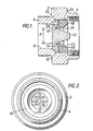
- the connector comprises a casing 2 having a screw threaded female inlet end 4 and a screw threaded male outlet end 6.
- the inlet end is adapted to receive a male coupling similar to the male end 6 of the connector illustrated, so that the inlet and outlet bores of the connector are effectively the size of the bore 8 in the outlet end as shown.
- a generally cylindrical chamber 10 having a step 12 of reduced diameter at the outlet end thereof.
- a dished support member 14 having a central circular fluid flow passage 16 therethrough is seated on the step 12 within the chamber.
- the member 14 supports a resilient ring 18 of elastomeric material which fits with clearance within the bore of the chamber 10 on the inlet side of the support.
- the elastomeric ring 18 has a central fluid flow passage 20 in alignment with the passage 16 through the support 14.
- the support member 14 carries two intersecting trapezoidal fins 22 which project through the central passage 20 in the elastomeric ring 18.
- the fins limit the inward deformation of the elastomeric ring under high fluid pressures and flow rates.
- the cross-section of the annular elastomeric ring 18 is essentially rectangular, modified by the provision of a chamfer 24 at the inner inlet side edge.
- the outer face 26 of the ring is cylindrical, and in the relaxed state this outer face has a clearance of not more than about 0.5 mm from the chamber wall, to permit fluid to penetrate to the outer face of the ring but not to flow readily past the outer face or to displace the ring laterally to any significant extent.
- the downstream or outlet face 28 of the elastomeric ring is substantially flat and meets the cylindrical outer face 26 with a small radius at 90°.
- This downstream face is supported by the support member 14 only at its outer rim, the support member being dished away from the elastomeric ring owing to a frusto-conical upstream surface 30 to the support member.
- the central flow passage 20 is substantially cylindrical, and the ratio between the diameter of the passage 20 and the outer diameter of the elastomeric ring 18 may suitably be from 1 : 1.2 to 1 : 1.3.
- the chamfered surface 24 may typically be formed at an angle of between 30° and 60°, suitably about 45°.
- the inward deformation of the elastomeric ring 18 is limited by the four outer edges of the fins 22, which accordingly delay the ultimate collapse of the ring into the flow passage under excessive pressure.
- the ratio of the diameter of the central flow passage 20 in the elastomeric member to the distance d across the fins measured where they start to project upstream is from 1 : 0.75 to 1 : 0.85, to allow a satisfactory inward deformation range.
Landscapes
- Engineering & Computer Science (AREA)
- General Engineering & Computer Science (AREA)
- Physics & Mathematics (AREA)
- General Physics & Mathematics (AREA)
- Automation & Control Theory (AREA)
- Mechanical Engineering (AREA)
- Pipe Accessories (AREA)
- Fluid-Pressure Circuits (AREA)
- Flow Control (AREA)
- Infusion, Injection, And Reservoir Apparatuses (AREA)
- Vehicle Body Suspensions (AREA)
- Quick-Acting Or Multi-Walled Pipe Joints (AREA)
- Paper (AREA)
- Safety Valves (AREA)
- Details Of Valves (AREA)
- Heat-Pump Type And Storage Water Heaters (AREA)
Priority Applications (1)
| Application Number | Priority Date | Filing Date | Title |
|---|---|---|---|
| AT87311344T ATE74414T1 (de) | 1986-12-29 | 1987-12-23 | Vorrichtung zur durchflussregelung. |
Applications Claiming Priority (2)
| Application Number | Priority Date | Filing Date | Title |
|---|---|---|---|
| GB8630945A GB2199639B (en) | 1986-12-29 | 1986-12-29 | Fluid flow control device |
| GB8630945 | 1986-12-29 |
Publications (2)
| Publication Number | Publication Date |
|---|---|
| EP0275697A1 true EP0275697A1 (de) | 1988-07-27 |
| EP0275697B1 EP0275697B1 (de) | 1992-04-01 |
Family
ID=10609625
Family Applications (1)
| Application Number | Title | Priority Date | Filing Date |
|---|---|---|---|
| EP87311344A Expired - Lifetime EP0275697B1 (de) | 1986-12-29 | 1987-12-23 | Vorrichtung zur Durchflussregelung |
Country Status (6)
| Country | Link |
|---|---|
| US (1) | US4883093A (de) |
| EP (1) | EP0275697B1 (de) |
| AT (1) | ATE74414T1 (de) |
| DE (1) | DE3777998D1 (de) |
| GB (1) | GB2199639B (de) |
| NO (1) | NO173351C (de) |
Cited By (2)
| Publication number | Priority date | Publication date | Assignee | Title |
|---|---|---|---|---|
| WO1991017382A1 (en) * | 1990-05-09 | 1991-11-14 | Turnbull, Caroline | Flow controlling device |
| FR2778760A1 (fr) * | 1998-05-15 | 1999-11-19 | Cahouet | Regulateur de pression d'un fluide |
Families Citing this family (22)
| Publication number | Priority date | Publication date | Assignee | Title |
|---|---|---|---|---|
| US5209265A (en) * | 1990-04-14 | 1993-05-11 | Matsushita Electric Works, Ltd. | Flow control device with restrictor |
| US5409042A (en) * | 1993-07-29 | 1995-04-25 | Romac Industries, Inc. | Constant-rate flow control valve |
| US5653264A (en) * | 1995-10-13 | 1997-08-05 | Atkinson; Louis D. | Fluid orifice device having encoded orifice size indicia |
| WO1997032244A1 (de) * | 1996-02-28 | 1997-09-04 | Oswaplast Ag | Durchflussregler mit einem regelkern für eine ausflussarmatur |
| AUPO359296A0 (en) * | 1996-11-12 | 1996-12-05 | Star Bright Pty Limited | Flow regulator |
| NL1011596C1 (nl) * | 1998-06-30 | 2000-01-04 | Watts Ocean B V | Debietbegrenzer. |
| DE19932596C2 (de) * | 1999-07-13 | 2002-10-17 | Wildfang Dieter Gmbh | Durchflußmengenregler |
| US7222643B2 (en) * | 2004-10-21 | 2007-05-29 | Vernay Laboratories, Inc. | Internal post flow control |
| WO2007146083A2 (en) * | 2006-06-06 | 2007-12-21 | Albert Montague | Backflow preventer valve |
| US8986253B2 (en) | 2008-01-25 | 2015-03-24 | Tandem Diabetes Care, Inc. | Two chamber pumps and related methods |
| US8408421B2 (en) | 2008-09-16 | 2013-04-02 | Tandem Diabetes Care, Inc. | Flow regulating stopcocks and related methods |
| CA2737461A1 (en) | 2008-09-19 | 2010-03-25 | Tandem Diabetes Care, Inc. | Solute concentration measurement device and related methods |
| EP2724739B1 (de) | 2009-07-30 | 2015-07-01 | Tandem Diabetes Care, Inc. | Tragbares Infusionspumpensystem |
| EP2428277B1 (de) | 2010-09-10 | 2014-06-11 | Itron France | Flüssigkeitsdurchflussregler |
| US8567445B2 (en) * | 2011-10-03 | 2013-10-29 | D.S. Magic Tech Llc | Water flow restriction device and method |
| US8714201B2 (en) * | 2012-02-07 | 2014-05-06 | Water Boger Hardware (Shenzhen) Co., Ltd. | Water-saving device structure |
| US9180242B2 (en) | 2012-05-17 | 2015-11-10 | Tandem Diabetes Care, Inc. | Methods and devices for multiple fluid transfer |
| US9173998B2 (en) | 2013-03-14 | 2015-11-03 | Tandem Diabetes Care, Inc. | System and method for detecting occlusions in an infusion pump |
| US9933792B2 (en) * | 2015-03-23 | 2018-04-03 | Lancer Corporation | Method and apparatus for flow regulation |
| US10359787B2 (en) * | 2017-10-11 | 2019-07-23 | Pao-Tang Chen | Two-way flow control valve |
| US10401877B2 (en) * | 2017-12-19 | 2019-09-03 | Nelson Irrigation Corporation | Flow washer assembly |
| DE202018102383U1 (de) * | 2018-04-27 | 2019-07-30 | Neoperl Gmbh | Durchflussmengenregler |
Citations (3)
| Publication number | Priority date | Publication date | Assignee | Title |
|---|---|---|---|---|
| US2454929A (en) * | 1944-07-17 | 1948-11-30 | Dole Valve Co | Flow control |
| FR2338437A1 (fr) * | 1976-01-16 | 1977-08-12 | France Etat | Reducteur de debit |
| EP0230715A1 (de) * | 1985-10-25 | 1987-08-05 | Vernay Laboratories, Inc. | Variabler Durchflussmengenregler |
Family Cites Families (18)
| Publication number | Priority date | Publication date | Assignee | Title |
|---|---|---|---|---|
| US2899979A (en) * | 1959-08-18 | Flow control device | ||
| US2568519A (en) * | 1946-01-16 | 1951-09-18 | Maytag Co | Automatic flow regulator |
| US2781061A (en) * | 1954-01-08 | 1957-02-12 | Gen Motors Corp | Flow controller |
| US2829674A (en) * | 1954-06-11 | 1958-04-08 | August L Segelhorst | Automatic fluid control means |
| US2936788A (en) * | 1955-04-26 | 1960-05-17 | Dole Valve Co | Flow control system |
| GB804705A (en) * | 1956-08-14 | 1958-11-19 | Hays Mfg Co | Improvements in or relating to flow control devices |
| GB884608A (en) * | 1959-06-01 | 1961-12-13 | Dole Valve Co | Improvements in or relating to fluid flow control devices |
| US3141477A (en) * | 1961-07-19 | 1964-07-21 | American Radiator & Standard | Fluid flow control means |
| GB960495A (en) * | 1961-12-20 | 1964-06-10 | Eric Alfred Schroeder | An improved fluid flow control device |
| GB1032596A (en) * | 1963-09-24 | 1966-06-15 | Shafer Homer John | Improvements in fluid flow control valves |
| GB1110292A (en) * | 1965-07-27 | 1968-04-18 | John Marwell Sheardown | Improvements in or relating to fluid flow control devices |
| US3409050A (en) * | 1965-10-12 | 1968-11-05 | Harry Swartz | Flow restrictor |
| DE2616566B2 (de) * | 1976-04-14 | 1979-12-13 | Dieter Wildfang Kg, 7840 Muellheim | Durchflußbegrenzer für in Leitungen strömende Medien |
| GB1542849A (en) * | 1976-06-16 | 1979-03-28 | Dennis C | Fluid flow device |
| CH622327A5 (de) * | 1977-04-15 | 1981-03-31 | Luwa Ag | |
| DE3025457A1 (de) * | 1980-05-23 | 1981-12-03 | Asulab AG, 2502 Bienne | Ventil und blutdruckmesseinrichtung mit einem ventil |
| EP0045668A1 (de) * | 1980-08-06 | 1982-02-10 | Peter Steer Developments Limited | Vorrichtung zum Dosieren von Flüssigkeiten |
| US4492339A (en) * | 1983-03-02 | 1985-01-08 | Nelson Irrigation Corporation | Flow control nozzle |
-
1986
- 1986-12-29 GB GB8630945A patent/GB2199639B/en not_active Expired - Fee Related
-
1987
- 1987-12-23 AT AT87311344T patent/ATE74414T1/de not_active IP Right Cessation
- 1987-12-23 EP EP87311344A patent/EP0275697B1/de not_active Expired - Lifetime
- 1987-12-23 DE DE8787311344T patent/DE3777998D1/de not_active Expired - Fee Related
- 1987-12-28 NO NO875443A patent/NO173351C/no unknown
- 1987-12-28 US US07/137,981 patent/US4883093A/en not_active Expired - Fee Related
Patent Citations (3)
| Publication number | Priority date | Publication date | Assignee | Title |
|---|---|---|---|---|
| US2454929A (en) * | 1944-07-17 | 1948-11-30 | Dole Valve Co | Flow control |
| FR2338437A1 (fr) * | 1976-01-16 | 1977-08-12 | France Etat | Reducteur de debit |
| EP0230715A1 (de) * | 1985-10-25 | 1987-08-05 | Vernay Laboratories, Inc. | Variabler Durchflussmengenregler |
Cited By (5)
| Publication number | Priority date | Publication date | Assignee | Title |
|---|---|---|---|---|
| WO1991017382A1 (en) * | 1990-05-09 | 1991-11-14 | Turnbull, Caroline | Flow controlling device |
| FR2661956A1 (fr) * | 1990-05-09 | 1991-11-15 | Trevor Caroline Turnbull | Procede et dispositif de controle de debit. |
| BE1003406A3 (fr) * | 1990-05-09 | 1992-03-17 | Trevor Turnbull | Dispositif de reglage d'ecoulement. |
| GR910100194A (el) * | 1990-05-09 | 1992-07-30 | Turnbull Caroline | Διαταξις ελεγχου ροης. |
| FR2778760A1 (fr) * | 1998-05-15 | 1999-11-19 | Cahouet | Regulateur de pression d'un fluide |
Also Published As
| Publication number | Publication date |
|---|---|
| DE3777998D1 (de) | 1992-05-07 |
| NO875443L (no) | 1988-06-30 |
| ATE74414T1 (de) | 1992-04-15 |
| GB2199639B (en) | 1991-03-27 |
| US4883093A (en) | 1989-11-28 |
| EP0275697B1 (de) | 1992-04-01 |
| NO173351C (no) | 1993-12-01 |
| GB2199639A (en) | 1988-07-13 |
| NO875443D0 (no) | 1987-12-28 |
| NO173351B (no) | 1993-08-23 |
| GB8630945D0 (en) | 1987-02-04 |
Similar Documents
| Publication | Publication Date | Title |
|---|---|---|
| US4883093A (en) | Fluid flow control device | |
| US3973732A (en) | Quick-connect fittings for a trickle type irrigation system | |
| US4687143A (en) | Drip irrigation apparatus | |
| US3957292A (en) | Quick-connect fittings for a trickle type irrigation system | |
| US5934328A (en) | In-line venturi | |
| EP0230715A1 (de) | Variabler Durchflussmengenregler | |
| EP0044494A1 (de) | Düse für eine Ringstrahlpumpe | |
| US3908694A (en) | Emitter valve for subterranean irrigation systems | |
| CA2666141A1 (en) | Flow control systems and control valves therefor | |
| EP0006755A1 (de) | Riesel-Bewässerungssystem und Durchflusssteuerventil hierfür | |
| EP2951476B1 (de) | Rückschlagventilanordnung und verfahren | |
| CN100491793C (zh) | 内部立柱式流量控制器 | |
| US4971117A (en) | Screen and flow regulator assembly | |
| WO1992011483A1 (en) | Variable orifice devices | |
| US3958761A (en) | Water discharge device for use with irrigation systems | |
| US4830057A (en) | Screen and flow regulator assembly | |
| US2709606A (en) | Pipe coupling having perforated socket for solder | |
| US5287886A (en) | Gas line override valve | |
| CN116123308B (zh) | 一种压力调节器装置及其应用 | |
| US5312141A (en) | Adapter for discharge lines | |
| US6027043A (en) | Spraying device particularly useful as water mini-sprinkler | |
| US5628340A (en) | Automatic valve | |
| CA1305392C (en) | Excess flow control valve | |
| EP0008000A1 (de) | Hochdruck-Schnellanschlusskupplung zum Anschliessen von Feuerlöschschläuchen oder dergleichen an Wasserhähne von Druckwasserleitungen | |
| EP0104944A2 (de) | Hochdruckregelventil |
Legal Events
| Date | Code | Title | Description |
|---|---|---|---|
| PUAI | Public reference made under article 153(3) epc to a published international application that has entered the european phase |
Free format text: ORIGINAL CODE: 0009012 |
|
| AK | Designated contracting states |
Kind code of ref document: A1 Designated state(s): AT BE CH DE ES FR GB GR IT LI LU NL SE |
|
| 17P | Request for examination filed |
Effective date: 19890126 |
|
| 17Q | First examination report despatched |
Effective date: 19900709 |
|
| RAP1 | Party data changed (applicant data changed or rights of an application transferred) |
Owner name: HYDRO-TEC LIMITED |
|
| GRAA | (expected) grant |
Free format text: ORIGINAL CODE: 0009210 |
|
| ITF | It: translation for a ep patent filed | ||
| AK | Designated contracting states |
Kind code of ref document: B1 Designated state(s): AT BE CH DE ES FR GB GR IT LI LU NL SE |
|
| PG25 | Lapsed in a contracting state [announced via postgrant information from national office to epo] |
Ref country code: LI Effective date: 19920401 Ref country code: GR Free format text: LAPSE BECAUSE OF FAILURE TO SUBMIT A TRANSLATION OF THE DESCRIPTION OR TO PAY THE FEE WITHIN THE PRESCRIBED TIME-LIMIT Effective date: 19920401 Ref country code: FR Effective date: 19920401 Ref country code: CH Effective date: 19920401 Ref country code: BE Effective date: 19920401 Ref country code: AT Effective date: 19920401 |
|
| REF | Corresponds to: |
Ref document number: 74414 Country of ref document: AT Date of ref document: 19920415 Kind code of ref document: T |
|
| REF | Corresponds to: |
Ref document number: 3777998 Country of ref document: DE Date of ref document: 19920507 |
|
| PG25 | Lapsed in a contracting state [announced via postgrant information from national office to epo] |
Ref country code: ES Free format text: LAPSE BECAUSE OF FAILURE TO SUBMIT A TRANSLATION OF THE DESCRIPTION OR TO PAY THE FEE WITHIN THE PRESCRIBED TIME-LIMIT Effective date: 19920712 |
|
| REG | Reference to a national code |
Ref country code: CH Ref legal event code: PL |
|
| EN | Fr: translation not filed | ||
| PG25 | Lapsed in a contracting state [announced via postgrant information from national office to epo] |
Ref country code: LU Free format text: LAPSE BECAUSE OF NON-PAYMENT OF DUE FEES Effective date: 19921231 |
|
| PLBI | Opposition filed |
Free format text: ORIGINAL CODE: 0009260 |
|
| 26 | Opposition filed |
Opponent name: JOH. VAILLANT GMBH U. CO Effective date: 19921229 |
|
| NLR1 | Nl: opposition has been filed with the epo |
Opponent name: JOH. VAILLANT GMBH U.CO |
|
| PLBN | Opposition rejected |
Free format text: ORIGINAL CODE: 0009273 |
|
| STAA | Information on the status of an ep patent application or granted ep patent |
Free format text: STATUS: OPPOSITION REJECTED |
|
| 27O | Opposition rejected |
Effective date: 19940325 |
|
| NLR2 | Nl: decision of opposition | ||
| PGFP | Annual fee paid to national office [announced via postgrant information from national office to epo] |
Ref country code: SE Payment date: 19941216 Year of fee payment: 8 |
|
| PGFP | Annual fee paid to national office [announced via postgrant information from national office to epo] |
Ref country code: NL Payment date: 19941231 Year of fee payment: 8 |
|
| EAL | Se: european patent in force in sweden |
Ref document number: 87311344.3 |
|
| PGFP | Annual fee paid to national office [announced via postgrant information from national office to epo] |
Ref country code: DE Payment date: 19950206 Year of fee payment: 8 |
|
| PG25 | Lapsed in a contracting state [announced via postgrant information from national office to epo] |
Ref country code: SE Effective date: 19951224 |
|
| PG25 | Lapsed in a contracting state [announced via postgrant information from national office to epo] |
Ref country code: NL Effective date: 19960701 |
|
| NLV4 | Nl: lapsed or anulled due to non-payment of the annual fee |
Effective date: 19960701 |
|
| PG25 | Lapsed in a contracting state [announced via postgrant information from national office to epo] |
Ref country code: DE Effective date: 19960903 |
|
| PGFP | Annual fee paid to national office [announced via postgrant information from national office to epo] |
Ref country code: GB Payment date: 19981224 Year of fee payment: 12 |
|
| PG25 | Lapsed in a contracting state [announced via postgrant information from national office to epo] |
Ref country code: GB Free format text: LAPSE BECAUSE OF NON-PAYMENT OF DUE FEES Effective date: 19991223 |
|
| GBPC | Gb: european patent ceased through non-payment of renewal fee |
Effective date: 19991223 |
|
| PG25 | Lapsed in a contracting state [announced via postgrant information from national office to epo] |
Ref country code: IT Free format text: LAPSE BECAUSE OF NON-PAYMENT OF DUE FEES Effective date: 20051223 |
|
| PLAB | Opposition data, opponent's data or that of the opponent's representative modified |
Free format text: ORIGINAL CODE: 0009299OPPO |