EP0275914A2 - Dispositif pour amener la vapeur sur une bande comme le papier - Google Patents
Dispositif pour amener la vapeur sur une bande comme le papier Download PDFInfo
- Publication number
- EP0275914A2 EP0275914A2 EP88100379A EP88100379A EP0275914A2 EP 0275914 A2 EP0275914 A2 EP 0275914A2 EP 88100379 A EP88100379 A EP 88100379A EP 88100379 A EP88100379 A EP 88100379A EP 0275914 A2 EP0275914 A2 EP 0275914A2
- Authority
- EP
- European Patent Office
- Prior art keywords
- zone
- steam
- main
- outlet
- work surface
- Prior art date
- Legal status (The legal status is an assumption and is not a legal conclusion. Google has not performed a legal analysis and makes no representation as to the accuracy of the status listed.)
- Granted
Links
- 239000000463 material Substances 0.000 claims abstract description 20
- 238000007664 blowing Methods 0.000 claims abstract description 13
- 238000001704 evaporation Methods 0.000 claims abstract description 4
- 230000008020 evaporation Effects 0.000 claims abstract description 4
- 238000009826 distribution Methods 0.000 claims description 47
- 238000009833 condensation Methods 0.000 claims description 5
- 230000005494 condensation Effects 0.000 claims description 5
- 238000010438 heat treatment Methods 0.000 claims description 3
- 230000000149 penetrating effect Effects 0.000 claims description 3
- 230000004888 barrier function Effects 0.000 abstract description 6
- 238000009834 vaporization Methods 0.000 abstract description 2
- 230000008016 vaporization Effects 0.000 abstract description 2
- 239000003570 air Substances 0.000 description 2
- 230000000903 blocking effect Effects 0.000 description 2
- 230000000694 effects Effects 0.000 description 2
- 239000002245 particle Substances 0.000 description 2
- 238000010025 steaming Methods 0.000 description 2
- XLYOFNOQVPJJNP-UHFFFAOYSA-N water Substances O XLYOFNOQVPJJNP-UHFFFAOYSA-N 0.000 description 2
- 239000012080 ambient air Substances 0.000 description 1
- 238000010276 construction Methods 0.000 description 1
- 230000001627 detrimental effect Effects 0.000 description 1
- 238000007599 discharging Methods 0.000 description 1
- 238000001035 drying Methods 0.000 description 1
- 230000002349 favourable effect Effects 0.000 description 1
- 238000009413 insulation Methods 0.000 description 1
- 238000009827 uniform distribution Methods 0.000 description 1
Images

Classifications
-
- D—TEXTILES; PAPER
- D21—PAPER-MAKING; PRODUCTION OF CELLULOSE
- D21F—PAPER-MAKING MACHINES; METHODS OF PRODUCING PAPER THEREON
- D21F7/00—Other details of machines for making continuous webs of paper
- D21F7/008—Steam showers
-
- D—TEXTILES; PAPER
- D21—PAPER-MAKING; PRODUCTION OF CELLULOSE
- D21F—PAPER-MAKING MACHINES; METHODS OF PRODUCING PAPER THEREON
- D21F7/00—Other details of machines for making continuous webs of paper
Definitions
- the invention relates to a device for applying steam to a material web, such as paper, with a steam blow box, which has blow openings for the steam outlet in a housing wall delimiting an evaporation space, the blow openings being provided in a main zone and an input zone and an output zone.
- Such a device is known from US-PS 43 51 700.
- the temperature of the material web is increased by the steam condensing on the material web. This leads to better dewatering in papermaking, so that less water has to be evaporated in the drying section.
- a specific moisture profile can be achieved by changing the vapor applied across the web width.
- the steam blow box is arranged in the area of the gap between two co-operating rollers.
- the housing wall having the blowing openings has a curvature corresponding to the roller serving as the transport device.
- the steam jets emerging through the blow openings are directed approximately perpendicularly onto the cylindrical work surface.
- the steam jets occur in the entrance zone with higher pressure. Its task is to form a steam curtain that reduces the amount of air drawn in with the material web. In this way, the efficiency should be improved.
- the housing wall is curved away from the work surface, so that the steam jets emerge there approximately parallel to the work surface.
- the invention has for its object to provide a device of the type described above, in which the efficiency is increased by better utilization of the steam.
- This object is achieved in that the outlet direction of the blowing openings in the exit zone is inclined more towards the main zone than in the entrance zone.
- the exit direction of the blowing openings in the exit zone is preferably inclined more towards the main zone than in the entrance zone. This takes into account the fact that the steam wants to exit on the input side against the direction of movement of the paper web, but is entrained on the output side by the paper web.
- the exit direction of the blowing openings of the exit zone deviates by approximately 20 ° to 27 °, preferably approximately 22 °, from the normal to the work surface formed by the material web.
- the exit direction of the blast openings of the entry zone should be 15 ° to 21 0, preferably 18 °, from the perpendicular to the work surface. differ.
- blow openings of the entrance, main and exit zones each have an entrance, main or. Exit distribution space and that the output distribution space is connected to the steam supply line, that a front steam distribution duct runs between the main distribution space and the input distribution space and a rear steam distribution duct runs between the main distribution space and the output distribution space that the front steam distribution duct runs a widthwise number of holes is connected to the input distribution space and the rear steam distribution duct is connected to the output distribution space via a widthwise number of holes, and that the main distribution space is divided into a number of chambers each are connected to one of the steam distribution channels via a valve.
- the two steam channels ensure a uniform distribution of the steam in the inlet and outlet distribution space as well as a uniform supply of the steam to the valves of the chambers of the main distribution space. It also ensures that the steam jets in the input or. Exit zone are blown out at a higher speed and pressure than in the main zone. This supports the Sperrwir kung.
- the number and / or the cross section of the holes leading to the input distribution space should be smaller than for the holes leading to the output distribution space.
- the exit speed in the exit zone is therefore greater than in the entrance zone, which further improves the barrier effect.
- the steam distribution Anaele k is connected in series and are interconnected via a restrictor-adjusting means.
- the steam pressure in the two steam distribution channels can be set differently.
- the pressure in the inlet manifold and in the outlet manifold can be selected so that there is an optimal blocking effect.
- the front steam distribution duct is connected to the steam supply line at one end, both steam distribution ducts are connected to one another at the other end, and the chambers of the main distribution space are connected to the front steam distribution duct. This gives a short path for the steam to be fed to the main zone.
- the barrier effect is increased in that the entrance zone at the beginning and the exit zone at the end are each delimited by a wall element which extends in the width direction and is at a smaller distance from the work surface in the exit zone than in the entrance zone.
- the smaller distance on the output side results in a higher throttle resistance and thus the desired higher blocking effect.
- the greater distance on the input side prevents the wide slot formed in this way from being clogged by particles of material which may be entrained by the material web. This ensures that air can always enter the steaming chamber and that no vacuum generated by an associated suction device can press the steam blower box onto the web and thereby destroy it.
- the entrance zone at the beginning and the exit zone at the end are each delimited by a wall element which extends in the width direction and is provided with a heating device.
- the heating device ensures that at the ends of the steam blow box, which are cooled by the colder ambient air, there are no drip points where condensate drops falling onto the material web can impair the uniform temperature and humidity values.
- the wall element can be a tube that can be heated in its interior by steam condensation.
- a heater can be easily connected to the existing steam rooms.
- the housing wall in the main zone runs parallel to the work surface and in the input and output zones at mutually opposite angles to the work surface, and that the blow openings are formed by holes penetrating the housing wall perpendicularly. In this way, the desired inclination of the outlet direction of the blow openings is obtained with simple means.
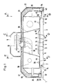
- a material web 1 made of paper is moved with the horizontal upper working surface 3 in the direction of the arrows 4.
- the material web 1 can be supported on the top of the wire section of a vacuum suction device of a paper machine or in some other way.
- An evaporation chamber 5 with a main zone 6, an entrance zone 7 and an exit zone 8 is located above the material web 1.
- the steam jets 14 and 16 are inclined towards the main zone 6. They deviate from the vertical to the work surface 3 in the input zone 7 by approximately 18 ° and in the output zone 8 by approximately 24 °.
- blow openings 11, 13 and 15 extend in two or more rows each across the entire width of the steam blow box 9.
- the blow openings 13 and 15 result on the inlet and outlet sides of vapor barriers, which prevent to a substantial extent that steam from the steaming chamber 5 at the point of introduction and in particular occurs at the point of execution of the material web.
- an extraordinarily large amount of steam can give off heat to the material web 1 by condensation.
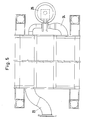
- the outlet plenum 22 is connected to the rear vapor distribution duct 21 through a number of larger-diameter holes 26 distributed across the width.
- the inlet manifold 18 is connected to the front vapor distribution duct 19 through a number of holes 27 smaller average distributed in the width direction.
- the main distribution space 20 is divided into a plurality of chambers 28 which are separated from one another by walls 29 running in the longitudinal direction, that is to say are arranged next to one another in the width direction.
- Each chamber 28 is supplied with steam from the front steam distribution channel 19 via a pipe 30 and a valve 31.
- the valve control takes place via an actuator 32, for example a pneumatic actuator.
- a wall element 33 At the beginning of the entrance zone 7 there is a wall element 33 and at the end of the exit zone 8 there is a wall element 34.
- the latter has a smaller distance from the work surface 3 than the wall element on the entrance side.
- Both wall elements are designed as a tube with a rectangular cross-section. They are connected at one end to a line 35 or 36, which leads from the front or rear steam distribution channel 19, 21. As a result, these wall elements are heated by condensation in such a way that water particles located on the outside can evaporate, ie they cannot have a detrimental effect on the material web 1.
- Drainage openings are provided wherever condensation could take place, for example openings 37 to 43, possibly with associated drainage channels.
- the housing wall 10 has a central horizontal section 44, an inclined, flat section 45 on the inlet side and an oppositely inclined, flat section 46 on the outlet side, the blow openings 11, 13 and 15 being formed by bores penetrating the housing wall perpendicularly.
- the individual housing wall sections 44, 45 and 46 can have a corresponding curvature, but should retain their inclination assignment. Instead, it is also possible to insert nozzles in the housing wall, which have the desired direction, or to provide inclined bores.
- the steam blower box can also be used - in the opposite position - for steam application from below. Then the drainage channel with the opening 40 in the main zone is omitted. And the drainage openings 37 to 43 are moved to the then lower position.
Landscapes
- Paper (AREA)
- Drying Of Solid Materials (AREA)
- Treatment Of Fiber Materials (AREA)
Priority Applications (1)
| Application Number | Priority Date | Filing Date | Title |
|---|---|---|---|
| AT88100379T ATE92556T1 (de) | 1987-01-20 | 1988-01-13 | Vorrichtung zum aufbringen von dampf auf eine materialbahn, wie papier. |
Applications Claiming Priority (2)
| Application Number | Priority Date | Filing Date | Title |
|---|---|---|---|
| DE19873701406 DE3701406A1 (de) | 1987-01-20 | 1987-01-20 | Vorrichtung zum aufbringen von dampf auf eine materialbahn, wie papier |
| DE3701406 | 1987-01-20 |
Publications (3)
| Publication Number | Publication Date |
|---|---|
| EP0275914A2 true EP0275914A2 (fr) | 1988-07-27 |
| EP0275914A3 EP0275914A3 (fr) | 1991-04-17 |
| EP0275914B1 EP0275914B1 (fr) | 1993-08-04 |
Family
ID=6319084
Family Applications (1)
| Application Number | Title | Priority Date | Filing Date |
|---|---|---|---|
| EP88100379A Expired - Lifetime EP0275914B1 (fr) | 1987-01-20 | 1988-01-13 | Dispositif pour amener la vapeur sur une bande comme le papier |
Country Status (6)
| Country | Link |
|---|---|
| US (1) | US4915788A (fr) |
| EP (1) | EP0275914B1 (fr) |
| AT (1) | ATE92556T1 (fr) |
| CA (1) | CA1296937C (fr) |
| DE (1) | DE3701406A1 (fr) |
| ES (1) | ES2042603T3 (fr) |
Cited By (4)
| Publication number | Priority date | Publication date | Assignee | Title |
|---|---|---|---|---|
| WO1991014045A1 (fr) * | 1990-03-09 | 1991-09-19 | Devron-Hercules Inc. | Douche a vapeur a egouttage reduit du condensat |
| DE4125062A1 (de) * | 1991-07-29 | 1993-02-04 | Vib Apparatebau Gmbh | Dampfblaskasten |
| EP0531739A1 (fr) * | 1991-09-12 | 1993-03-17 | Valmet Paper Machinery Inc. | Distributeur de vapeur |
| EP0609544A1 (fr) * | 1993-01-16 | 1994-08-10 | V.I.B. Apparatebau GmbH | Procédé et dispositif pour améliorer la brillance et/ou le lissé d'une bande |
Families Citing this family (35)
| Publication number | Priority date | Publication date | Assignee | Title |
|---|---|---|---|---|
| DE3701407C1 (de) * | 1987-01-20 | 1988-04-07 | V I B Appbau Gmbh | Dampfblaskasten |
| US6322667B1 (en) * | 1994-07-04 | 2001-11-27 | Mcgill University | Paper and paperboard of improved mechanical properties |
| US5470436A (en) * | 1994-11-09 | 1995-11-28 | International Paper Company | Rewetting of paper products during drying |
| FI96389C (fi) * | 1994-12-02 | 1996-06-25 | Valmet Paper Machinery Inc | Menetelmä ja laitteisto paperiradan tai vastaavan päällystysaseman ilmastoimiseksi |
| US6143135A (en) * | 1996-05-14 | 2000-11-07 | Kimberly-Clark Worldwide, Inc. | Air press for dewatering a wet web |
| US6083346A (en) * | 1996-05-14 | 2000-07-04 | Kimberly-Clark Worldwide, Inc. | Method of dewatering wet web using an integrally sealed air press |
| US6149767A (en) * | 1997-10-31 | 2000-11-21 | Kimberly-Clark Worldwide, Inc. | Method for making soft tissue |
| US6096169A (en) * | 1996-05-14 | 2000-08-01 | Kimberly-Clark Worldwide, Inc. | Method for making cellulosic web with reduced energy input |
| US6197154B1 (en) | 1997-10-31 | 2001-03-06 | Kimberly-Clark Worldwide, Inc. | Low density resilient webs and methods of making such webs |
| US6187137B1 (en) | 1997-10-31 | 2001-02-13 | Kimberly-Clark Worldwide, Inc. | Method of producing low density resilient webs |
| DE19800955A1 (de) * | 1998-01-13 | 1999-07-15 | Voith Sulzer Papiertech Patent | Vorrichtung zum Auftragen eines flüssigen oder pastösen Auftragsmediums auf eine laufende Materialbahn, insbesondere aus Papier oder Karton |
| DE19800954A1 (de) * | 1998-01-13 | 1999-07-15 | Voith Sulzer Papiertech Patent | Vorrichtung zum direkten oder indirekten Auftragen eines flüssigen oder pastösen Auftragsmediums auf eine laufende Materialbahn, insbesondere aus Papier oder Karton |
| DE19824170A1 (de) * | 1998-05-29 | 1999-12-02 | Voith Sulzer Papiertech Patent | Einrichtung zum Befeuchten einer Materialbahn |
| US6306257B1 (en) | 1998-06-17 | 2001-10-23 | Kimberly-Clark Worldwide, Inc. | Air press for dewatering a wet web |
| US6280573B1 (en) | 1998-08-12 | 2001-08-28 | Kimberly-Clark Worldwide, Inc. | Leakage control system for treatment of moving webs |
| FI4283U1 (fi) * | 1999-09-06 | 1999-12-31 | Neles Automation Oy | Höyrylaatikko |
| FI107065B (fi) | 1999-10-21 | 2001-05-31 | Metso Paper Automation Oy | Paperikoneen höyrylaatikko |
| DE19951794A1 (de) * | 1999-10-27 | 2001-05-03 | Voith Paper Patent Gmbh | Verfahren und Vorrichtung zur Entwässerung einer Faserstoffbahn |
| US6318727B1 (en) | 1999-11-05 | 2001-11-20 | Kimberly-Clark Worldwide, Inc. | Apparatus for maintaining a fluid seal with a moving substrate |
| US6484418B1 (en) | 2000-11-06 | 2002-11-26 | Kimberly-Clark Worldwide, Inc. | Yankee drying hood and method comprising angled impingement nozzles |
| JP3848168B2 (ja) | 2001-03-29 | 2006-11-22 | 三菱製紙株式会社 | カーテン塗布装置 |
| US8261465B2 (en) * | 2002-09-10 | 2012-09-11 | Voith Paper Patent Gmbh | Equipment and method for producing and/or treating a fibrous web |
| DE10242010A1 (de) * | 2002-09-11 | 2004-03-25 | Voith Paper Patent Gmbh | Vorrichtung und Verfahren zum Medienauftrag auf einen sich bewegenden Untergrund |
| DE10322524A1 (de) * | 2003-05-19 | 2004-12-23 | Voith Paper Patent Gmbh | Dichtungseinrichtung |
| DE10352980B4 (de) * | 2003-11-13 | 2006-10-12 | V.I.B. Systems Gmbh | Dampfblaskasten |
| DE102004014597B4 (de) * | 2004-03-23 | 2008-02-14 | M-Real Oyj | Vorrichtung zum Behandeln einer Papier- oder Kartonbahn |
| US7634860B2 (en) * | 2004-05-03 | 2009-12-22 | Transphase Technology, Ltd. | Steam box |
| DE102004064010B4 (de) * | 2004-06-08 | 2007-03-08 | V.I.B. Systems Gmbh | Verfahren zur Steuerung von Dampfmenge und/oder Dampfaustrittsgeschwindigkeit aus den Dampfaustrittsöffnungen eines Dampfblaskastens |
| CN104213457B (zh) * | 2014-08-26 | 2016-05-04 | 华南理工大学 | 一种三区蒸汽箱及调节纸张的横幅水份含量的方法 |
| CN104195866B (zh) * | 2014-08-26 | 2016-05-04 | 华南理工大学 | 一种二次调节蒸汽箱及调节纸张的横幅水份含量的方法 |
| CN113981730B (zh) * | 2021-10-25 | 2023-07-11 | 浙江华章科技有限公司 | 一种智能造纸机分区蒸汽加湿装置 |
| CN113969515B (zh) * | 2021-10-25 | 2023-07-11 | 浙江华章科技有限公司 | 一种智能造纸机分区蒸汽加湿系统及控制方法 |
| CN114197241B (zh) * | 2021-11-22 | 2023-07-14 | 浙江华章科技有限公司 | 一种具有防凝结水保温喷嘴的造纸机加湿器 |
| CN114197240B (zh) * | 2021-11-22 | 2023-07-14 | 浙江华章科技有限公司 | 一种避免纸张塑化爆裂的纸板蒸汽加湿装置及其使用方法 |
| CN114182567B (zh) * | 2021-11-22 | 2023-07-11 | 浙江华章科技有限公司 | 一种精确控温控压的分区蒸汽加湿设备及其使用方法 |
Family Cites Families (9)
| Publication number | Priority date | Publication date | Assignee | Title |
|---|---|---|---|---|
| US3549070A (en) * | 1969-02-27 | 1970-12-22 | Tec Systems | Floatation of sheet materials |
| US3945570A (en) * | 1974-12-10 | 1976-03-23 | Devron Engineering Ltd. | Steam supply apparatus |
| FI60261C (fi) * | 1980-03-28 | 1981-12-10 | Valmet Oy | Oevertrycksmunstycke foer behandling av banor |
| US4320583A (en) * | 1980-06-23 | 1982-03-23 | Dove Norman F | Steam distribution apparatus for flat paper sheet |
| US4351700A (en) * | 1980-06-23 | 1982-09-28 | Dove Norman F | Steam distribution apparatus for the nip of two rolls |
| US4358900A (en) * | 1980-09-24 | 1982-11-16 | Dove Norman F | Apparatus to supply steam including steam evacuation |
| US4444622A (en) * | 1980-09-29 | 1984-04-24 | Devron Engineering Ltd. | Steam distribution |
| US4414757A (en) * | 1981-10-07 | 1983-11-15 | Overly, Incorporated | Web dryer nozzle assembly |
| US4685221A (en) * | 1986-02-28 | 1987-08-11 | Thermo Electron - Web Systems, Inc. | Steam-shower apparatus and method of using same |
-
1987
- 1987-01-20 DE DE19873701406 patent/DE3701406A1/de active Granted
- 1987-08-07 CA CA000543965A patent/CA1296937C/fr not_active Expired - Lifetime
-
1988
- 1988-01-13 ES ES88100379T patent/ES2042603T3/es not_active Expired - Lifetime
- 1988-01-13 EP EP88100379A patent/EP0275914B1/fr not_active Expired - Lifetime
- 1988-01-13 AT AT88100379T patent/ATE92556T1/de not_active IP Right Cessation
-
1989
- 1989-01-24 US US07/302,075 patent/US4915788A/en not_active Expired - Lifetime
Cited By (8)
| Publication number | Priority date | Publication date | Assignee | Title |
|---|---|---|---|---|
| WO1991014045A1 (fr) * | 1990-03-09 | 1991-09-19 | Devron-Hercules Inc. | Douche a vapeur a egouttage reduit du condensat |
| US5211813A (en) * | 1990-03-09 | 1993-05-18 | Sawley David J | Steam shower with reduced condensate drip |
| DE4125062A1 (de) * | 1991-07-29 | 1993-02-04 | Vib Apparatebau Gmbh | Dampfblaskasten |
| EP0528160A1 (fr) * | 1991-07-29 | 1993-02-24 | V.I.B. Apparatebau GmbH | Diffuseur de vapeur |
| EP0531739A1 (fr) * | 1991-09-12 | 1993-03-17 | Valmet Paper Machinery Inc. | Distributeur de vapeur |
| US5355595A (en) * | 1991-09-12 | 1994-10-18 | Valmet Paper Machinery, Inc. | Steam box |
| EP0609544A1 (fr) * | 1993-01-16 | 1994-08-10 | V.I.B. Apparatebau GmbH | Procédé et dispositif pour améliorer la brillance et/ou le lissé d'une bande |
| US5914008A (en) * | 1993-01-16 | 1999-06-22 | V.I.B. Apparatebau Gmbh | Method for increasing the gloss and smoothness of a web of material |
Also Published As
| Publication number | Publication date |
|---|---|
| US4915788A (en) | 1990-04-10 |
| CA1296937C (fr) | 1992-03-10 |
| ES2042603T3 (es) | 1993-12-16 |
| DE3701406C2 (fr) | 1988-10-27 |
| DE3701406A1 (de) | 1988-07-28 |
| EP0275914A3 (fr) | 1991-04-17 |
| EP0275914B1 (fr) | 1993-08-04 |
| ATE92556T1 (de) | 1993-08-15 |
Similar Documents
| Publication | Publication Date | Title |
|---|---|---|
| EP0275914B1 (fr) | Dispositif pour amener la vapeur sur une bande comme le papier | |
| DE19534573C2 (de) | Dampfblaskasten und Verfahren zum zonenweisen Temperieren einer laufenden Papierbahn | |
| DE9320455U1 (de) | Vorrichtung zum Erhöhen von Glanz und/oder Glätte einer Materialbahn | |
| DE3818600C2 (fr) | ||
| DE69205778T2 (de) | Dampfblaskasten. | |
| DE19623471C1 (de) | Belüftungsdüse | |
| EP1678452A1 (fr) | S choir pour l ments de placage | |
| DE1710592B2 (de) | Vorrichtung zum Dampfen eines schlauch! örmigen Stoffes, insbesondere von Wirkware | |
| DE3701407C1 (de) | Dampfblaskasten | |
| EP0319681A2 (fr) | Dispositif pour le traitement thermique d'une large bande de textile en déplacement continu | |
| DE19500752C2 (de) | Dampfbefeuchtungseinrichtung | |
| EP0471162B1 (fr) | Dispositif de séchage et/ou de fixation à convection | |
| EP0298299A1 (fr) | Dispositif pour guider des bandes sans contact direct | |
| DE2121963B2 (de) | Plattenverdampfer mit fallendem fluessigkeitsfilm | |
| DE1206718B (de) | Trockenvorrichtung fuer Faserstoffbahnen | |
| DE10352980B4 (de) | Dampfblaskasten | |
| EP0802276A2 (fr) | Machine pour la fabrication d'une bande de matériau | |
| DE102005031444A1 (de) | Vorrichtung zum Befeuchten einer Materialbahn | |
| DE102004027972B4 (de) | Dampfblaskasten | |
| DE3443603A1 (de) | Geblaese fuer eine papierbahn-trocknungseinrichtung | |
| EP0960978B1 (fr) | Dispositif pour l' humidification d' une bande de matériau | |
| DE2724328C2 (de) | Trockner für Warenbahnen, insbesondere im Rollenoffset und Schwebedüse, insbesondere zur Verwendung in dem Trockner | |
| DE102009026846A1 (de) | Verfahren zur Steuerung des Trockengehaltes einer Materialbahn, insbesondere Faserstoffbahn in einer Pressenvorrichtung und Pressenvorrichtung | |
| DE60022149T2 (de) | Dampfblaskasten in einer Papiermaschine | |
| DE4311397A1 (en) | Paper making machine - has drying sections with suction and blow elements combined in a vertical structure towards the drying cylinders |
Legal Events
| Date | Code | Title | Description |
|---|---|---|---|
| PUAI | Public reference made under article 153(3) epc to a published international application that has entered the european phase |
Free format text: ORIGINAL CODE: 0009012 |
|
| AK | Designated contracting states |
Kind code of ref document: A2 Designated state(s): AT BE CH ES FR GB IT LI LU NL SE |
|
| PUAL | Search report despatched |
Free format text: ORIGINAL CODE: 0009013 |
|
| AK | Designated contracting states |
Kind code of ref document: A3 Designated state(s): AT BE CH ES FR GB IT LI LU NL SE |
|
| 17P | Request for examination filed |
Effective date: 19911001 |
|
| 17Q | First examination report despatched |
Effective date: 19921229 |
|
| GRAA | (expected) grant |
Free format text: ORIGINAL CODE: 0009210 |
|
| AK | Designated contracting states |
Kind code of ref document: B1 Designated state(s): AT BE CH ES FR GB IT LI LU NL SE |
|
| REF | Corresponds to: |
Ref document number: 92556 Country of ref document: AT Date of ref document: 19930815 Kind code of ref document: T |
|
| GBT | Gb: translation of ep patent filed (gb section 77(6)(a)/1977) |
Effective date: 19930811 |
|
| ITF | It: translation for a ep patent filed | ||
| ET | Fr: translation filed | ||
| REG | Reference to a national code |
Ref country code: ES Ref legal event code: FG2A Ref document number: 2042603 Country of ref document: ES Kind code of ref document: T3 |
|
| PG25 | Lapsed in a contracting state [announced via postgrant information from national office to epo] |
Ref country code: LU Free format text: LAPSE BECAUSE OF NON-PAYMENT OF DUE FEES Effective date: 19940131 Ref country code: LI Effective date: 19940131 Ref country code: CH Effective date: 19940131 Ref country code: BE Effective date: 19940131 |
|
| PLBE | No opposition filed within time limit |
Free format text: ORIGINAL CODE: 0009261 |
|
| STAA | Information on the status of an ep patent application or granted ep patent |
Free format text: STATUS: NO OPPOSITION FILED WITHIN TIME LIMIT |
|
| 26N | No opposition filed | ||
| BERE | Be: lapsed |
Owner name: V.I.B. APPARATEBAU G.M.B.H. Effective date: 19940131 |
|
| PG25 | Lapsed in a contracting state [announced via postgrant information from national office to epo] |
Ref country code: NL Effective date: 19940801 |
|
| NLV4 | Nl: lapsed or anulled due to non-payment of the annual fee | ||
| REG | Reference to a national code |
Ref country code: CH Ref legal event code: PL |
|
| EAL | Se: european patent in force in sweden |
Ref document number: 88100379.2 |
|
| REG | Reference to a national code |
Ref country code: GB Ref legal event code: IF02 |
|
| PGFP | Annual fee paid to national office [announced via postgrant information from national office to epo] |
Ref country code: SE Payment date: 20041203 Year of fee payment: 18 |
|
| PGFP | Annual fee paid to national office [announced via postgrant information from national office to epo] |
Ref country code: GB Payment date: 20041208 Year of fee payment: 18 |
|
| PGFP | Annual fee paid to national office [announced via postgrant information from national office to epo] |
Ref country code: ES Payment date: 20041209 Year of fee payment: 18 |
|
| PGFP | Annual fee paid to national office [announced via postgrant information from national office to epo] |
Ref country code: FR Payment date: 20041216 Year of fee payment: 18 |
|
| PGFP | Annual fee paid to national office [announced via postgrant information from national office to epo] |
Ref country code: AT Payment date: 20050131 Year of fee payment: 18 |
|
| PG25 | Lapsed in a contracting state [announced via postgrant information from national office to epo] |
Ref country code: GB Free format text: LAPSE BECAUSE OF NON-PAYMENT OF DUE FEES Effective date: 20060113 Ref country code: AT Free format text: LAPSE BECAUSE OF NON-PAYMENT OF DUE FEES Effective date: 20060113 |
|
| PG25 | Lapsed in a contracting state [announced via postgrant information from national office to epo] |
Ref country code: SE Free format text: LAPSE BECAUSE OF NON-PAYMENT OF DUE FEES Effective date: 20060114 Ref country code: ES Free format text: LAPSE BECAUSE OF NON-PAYMENT OF DUE FEES Effective date: 20060114 |
|
| PG25 | Lapsed in a contracting state [announced via postgrant information from national office to epo] |
Ref country code: FR Free format text: LAPSE BECAUSE OF NON-PAYMENT OF DUE FEES Effective date: 20060131 |
|
| PGFP | Annual fee paid to national office [announced via postgrant information from national office to epo] |
Ref country code: IT Payment date: 20060131 Year of fee payment: 19 |
|
| EUG | Se: european patent has lapsed | ||
| GBPC | Gb: european patent ceased through non-payment of renewal fee |
Effective date: 20060113 |
|
| REG | Reference to a national code |
Ref country code: FR Ref legal event code: ST Effective date: 20060929 |
|
| REG | Reference to a national code |
Ref country code: ES Ref legal event code: FD2A Effective date: 20060114 |
|
| PG25 | Lapsed in a contracting state [announced via postgrant information from national office to epo] |
Ref country code: IT Free format text: LAPSE BECAUSE OF NON-PAYMENT OF DUE FEES Effective date: 20070113 |