EP0275983A1 - Appareil de coupure en moyenne tension pour courant continu de forte intensité - Google Patents
Appareil de coupure en moyenne tension pour courant continu de forte intensité Download PDFInfo
- Publication number
- EP0275983A1 EP0275983A1 EP88100700A EP88100700A EP0275983A1 EP 0275983 A1 EP0275983 A1 EP 0275983A1 EP 88100700 A EP88100700 A EP 88100700A EP 88100700 A EP88100700 A EP 88100700A EP 0275983 A1 EP0275983 A1 EP 0275983A1
- Authority
- EP
- European Patent Office
- Prior art keywords
- contacts
- passages
- refrigerant
- condenser
- supplying
- Prior art date
- Legal status (The legal status is an assumption and is not a legal conclusion. Google has not performed a legal analysis and makes no representation as to the accuracy of the status listed.)
- Granted
Links
- 239000002826 coolant Substances 0.000 claims abstract description 12
- 239000003507 refrigerant Substances 0.000 claims description 22
- 239000007788 liquid Substances 0.000 claims description 6
- 239000004033 plastic Substances 0.000 claims description 3
- 239000012809 cooling fluid Substances 0.000 abstract 2
- 238000001816 cooling Methods 0.000 description 8
- 239000003570 air Substances 0.000 description 6
- 238000010438 heat treatment Methods 0.000 description 3
- BOSAWIQFTJIYIS-UHFFFAOYSA-N 1,1,1-trichloro-2,2,2-trifluoroethane Chemical compound FC(F)(F)C(Cl)(Cl)Cl BOSAWIQFTJIYIS-UHFFFAOYSA-N 0.000 description 1
- 230000003213 activating effect Effects 0.000 description 1
- 239000012080 ambient air Substances 0.000 description 1
- 230000000052 comparative effect Effects 0.000 description 1
- 230000005494 condensation Effects 0.000 description 1
- 238000009833 condensation Methods 0.000 description 1
- 230000002706 hydrostatic effect Effects 0.000 description 1
- 230000001939 inductive effect Effects 0.000 description 1
- 239000007791 liquid phase Substances 0.000 description 1
- 239000000463 material Substances 0.000 description 1
- -1 polytetrafluoroethylene Polymers 0.000 description 1
- 229920001343 polytetrafluoroethylene Polymers 0.000 description 1
- 239000004810 polytetrafluoroethylene Substances 0.000 description 1
- 238000005057 refrigeration Methods 0.000 description 1
- 238000009423 ventilation Methods 0.000 description 1
- XLYOFNOQVPJJNP-UHFFFAOYSA-N water Substances O XLYOFNOQVPJJNP-UHFFFAOYSA-N 0.000 description 1
Images

Classifications
-
- H—ELECTRICITY
- H01—ELECTRIC ELEMENTS
- H01H—ELECTRIC SWITCHES; RELAYS; SELECTORS; EMERGENCY PROTECTIVE DEVICES
- H01H1/00—Contacts
- H01H1/62—Heating or cooling of contacts
-
- H—ELECTRICITY
- H01—ELECTRIC ELEMENTS
- H01H—ELECTRIC SWITCHES; RELAYS; SELECTORS; EMERGENCY PROTECTIVE DEVICES
- H01H33/00—High-tension or heavy-current switches with arc-extinguishing or arc-preventing means
- H01H33/002—Very heavy-current switches
Definitions
- the present invention relates to a medium voltage switching device for high intensity direct current, comprising a fixed contact and a movable contact, each provided with an internal passage for circulation of a coolant, and current leads to these contacts. .
- Document DE-A-2 303550 describes a selector for an inductive transformer or ballast, the contacts of which are cooled by a circulation of refrigerant, traveling through a closed circuit comprising a circulation pump and a cooling exchanger.
- this refrigerant remains constantly in the liquid phase, so that its capacity for cooling the contacts is limited.
- the rapid opening of switching devices with fixed contact and movable contact does not pose any particular difficulty when the currents which cross them are of intensity less than a thousand amperes.
- the intensities are higher, the masses in movement increase with the intensity and require, for a given opening speed, to increase the opening forces correspondingly, which poses mechanical resistance problems.
- the width of the movable contact, as well as the volume of the interrupting chamber which contains it, increases. There are then great difficulties, even impossiblitiés to cut certain currents.
- the object of the present invention is to provide a medium-voltage switching device for high-intensity direct current which makes it possible to ensure good cooling of the contacts, and therefore to reduce their dimensions, without however resorting to an auxiliary source of energy.
- the breaking device is characterized in that its coolant is vaporizable, and in that it further comprises at least one free-air air condenser, conduits for supplying the partially vaporized coolant from the passages through the contacts to the condenser, and conduits for '' Recondensed refrigerant to the passages through the contacts.
- It also preferably meets at least one of the following characteristics: - It further comprises a reservoir for the recondensed refrigerant liquid in the condenser, at least one conduit for supplying the recondensed refrigerant from the condenser to the recipe reservoir, and the conduits for supplying the recondensed refrigerant to the passages through the contacts leave of the recipe tank.
- the air condensers are fitted with vertical chimneys for evacuating the heated air in indirect heat exchange with the partially vaporized refrigerant.
- the conduits for supplying the coolant to the circulation passages through the contacts to the condenser, and for supplying the recondensed coolant to the passages through the contacts are made of flexible heat-resistant plastic.
- the diameters of the passages through the contacts are large enough to avoid any phenomenon of the cooling of the liquid refrigerant.
- the cooling of the contacts is therefore ensured by the change of liquid-vapor state of the refrigerant.
- This type of device is particularly interesting when the contacts are contained in a vacuum envelope, which makes it possible to increase the performance of the contacts.
- the device consists of a fixed contact 1 and a mobile contact 2.
- the position of the mobile contact when the contacts are opened is shown in phantom in 2A.
- the current inputs and outputs are made up of connections 3 and 4 and braids 5 and 6.
- the contacts are pierced with coolant passage bores 7.8.
- the diameter of these bores is sufficient to avoid the phenomena of heat build-up of the refrigerant.
- the latter is for example trichloro-trifluoroethane.
- the cooling circuit comprises two condensers 9, 10, surmounted by chimneys 18, 19 activating the vertical flow of refrigeration air ensuring the condensation of the partially vaporized refrigerant during its circulation through the passages 7, 8 passing through the contacts.
- supply conduits 11, 12 made of polytetrafluoroethylene, a flexible and heat-resistant plastic material.
- separators 13, 14 make it possible to separate the non-vaporized refrigerant, which is returned by conduits 15, 16 to its recipe reservoir 17, from the refrigerant in the vapor state.
- the refrigerant condenses in indirect heat exchange with the ambient air, which is evacuated via the chimneys 18, 19, and returns via the conduits 20, 21 to the liquid refrigerant recipe reservoir 17. The position of this tank is low enough to avoid a significant hydrostatic overpressure.
- conduits 22, then 23, 24 bring the coolant back to the passages through the contacts.
- the same contacts provided with a cooling device according to the invention, can allow the passage of a double current, ie 6000 amperes, by evacuating a calorific power of 800 watts and by heating only 50 ° C.
Landscapes
- Cooling Or The Like Of Electrical Apparatus (AREA)
- Cooling Or The Like Of Semiconductors Or Solid State Devices (AREA)
Abstract
Description
- La présente invention concerne un appareil de coupure en moyenne tension pour courant continu de forte intensité, comprenant un contact fixe et un contact mobile, munis chacun d'un passage interne de circulation d'un liquid réfrigérant, et des amenées de courant à ces contacts.
- Le document DE-A-2 303550 décrit un sélecteur pour transformateur ou ballast inductif dont les contacts sont refroidis par une circulation de réfrigérant, parcourant un circuit fermé comportant une pompe de circulation et un échangeur de refroidissement. Mais ce réfrigérant reste constamment en phase liquide, de sorte que sa capacité de refroidissement des contacts est limitée.
- L'ouverture rapide d'appareils de coupure à contact fixe et contact mobile ne pose pas de difficulté particulière quand les courants qui les traversent sont d'intensité inférieure au millier d'ampéres. Lorsque les intensités sont supérieures, les masses en mouvement augmentent avec l'intensité et nécessitent, pour une vitesse d'ouverture donnée, d'augmenter d'autant les efforts d'ouverture, ce qui pose des problèmes de tenue mécanique. La largeur du contact mobile, ainsi que le volume de la chambre de coupure qui le contient, augmentent. On constate alors de grandes difficultés, voire des impossiblitiés à couper certains courants.
- Par ailleurs, les conditions d'exploitation imposent une fiabilité qui interdit l'emploi d'une source auxiliaire d'énergie de refroidissement, soit ventilateur d'air, soit pompe de circulation d'eau, et exclut l'emploi de systèmes de ventilation forcée qui permettraient de réduire les dimensions des contacts.
- La présente invention a pour but de procurer un appareil de coupure en moyenne tension pour courant continu de forte intensité qui permette d'assurer un bon refroidissement des contacts, et donc de réduire leurs dimensions, sans cependant recourir à une source auxiliaire d'énergie.
- L'appareil de coupure selon l'invention est caractérisé en ce que son liquide réfrigérant est vaporisable, et en ce qu'il comporte en outre au moins un condenseur à air en circulation libre, des conduits d'amenée du liquide réfrigérant partiellement vaporisé des passages à travers les contacts au condenseur, et des conduits d'amenée du réfrigérant recondensé aux passages à travers les contacts.
- Il répond en outre de préférence à au moins l'une des caractéristiques suivantes :
- Il comporte de plus un réservoir de recette du liquide réfrigérant recondensé dans le condenseur, au moins un conduit d'amenée du réfrigérant recondensé du condenseur au réservoir de recette, et les conduits d'amenée du réfrigérant recondensé aux passages à travers les contacts partent du réservoir de recette.
- Les condenseurs à air sont munis de cheminées verticales d'évacuation de l'air réchauffé en échange indirect de chaleur avec le réfrigérant partiellement vaporisé.
- Les conduits d'amenée du liquide réfrigérant des passages de circulation à travers les contacts au condenseur, et d'amenée du liquide réfrigérant recondensé aux passages à travers les contacts, sont en matière plastique souple résistante à la chaleur.
- Les diamètres des passages à travers les contacts sont suffisamment grands pour éviter tout phénomène de caléfaction du réfrigérant liquide. - Le refroidissement des contacts est donc assuré par le changement d'état liquide-vapeur du réfrigérant. Ce type d'appareil est particulièrement intéressant losque les contacts sont contenus dans une enveloppe sous vide, qui permet d'augmenter les performances des contacts.
- Il est décrit ci-après, à titre d'exemple et en référence aux figures du dessin annexée, un appareil de coupure selon l'invention, permettant de doubler le courant permanent pour un même échauffement des contacts par rapport au courant admissible s'ils étaient refroidis par convection naturelle.
- - La figure 1 représente l'appareil de coupure en élévation.
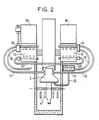
- - La figure 2 représente le même appareil en élévation vu à 90° de la figure 1.
- L'appareil se compose d'un contact fixe 1 et d'un contact mobile 2. La position du contact mobile en cas d'ouverture des contacts est représentée en trait mixte en 2A. Les entrées et sorties de courant sont constitées par les connexions 3 et 4 et les tresses 5 et 6.
- Les contacts sont percés d'alésages de passage de fluide réfrigérant 7,8. Le diamètre de ces alésages est suffisant pour éviter les phénomènes de caléfaction du réfrigérant. Ce dernier est par exemple du trichloro-trifluoréthane.
- Le circuit de refroidissement comprend deux condenseurs 9, 10, surmontés de cheminées 18, 19 activant le courant d'air vertical de réfrigération assurant la condensation du réfrigérant partiellement vaporisé lors de sa circulation par les passages 7, 8 traversant les contacts.
- Ces derniers sont reliés aux condenseurs par des conduits d'amenée 11, 12 en polytétrafluoréthylène, matière plastique souple et résistante à la chaleur.
- A l'entrée des condenseurs, des séparateurs 13, 14 permettent de séparer le réfrigérant non vaporisé, qui est renvoyé par des conduits 15, 16 à son réservoir de recette 17, du réfrigérant à l'état de vapeur. Dans les condenseurs, le réfrigérant se condense en échange indirect de chaleur avec l'air ambiant, qui s'évacue par les cheminées 18, 19, et revient par les conduits 20, 21 au réservoir de recette de réfrigérant liquide 17. La position de ce réservoir est suffisamment basse pour éviter une surpression hydrostatique notable.
- Du réservoir 17, des conduits 22, puis 23, 24 ramènent le fluide réfrigérant aux passages à travers les contacts.
- Des essais comparatifs ont montré que, pour des contacts refroidis en convection naturelle et s'échauffant à 100° C en fonctionnement, on peut admettre un courant de 3000 Ampères. Ceci correspond à une puissance calorifique à évacuer de 200 watts.
- Les mêmes contacts, munis d'un dispositif de refroidissement selon l'invention, peuvent permettre le passage d'un courant double, soit 6000 Ampères, en évacuant une puissance calorifique de 800 watts et en ne s'échauffant que de 50°C.
Claims (5)
Applications Claiming Priority (2)
| Application Number | Priority Date | Filing Date | Title |
|---|---|---|---|
| FR8700651A FR2609836A1 (fr) | 1987-01-21 | 1987-01-21 | Appareil de coupure en moyenne tension pour courant continu de forte intensite |
| FR8700651 | 1987-01-21 |
Publications (2)
| Publication Number | Publication Date |
|---|---|
| EP0275983A1 true EP0275983A1 (fr) | 1988-07-27 |
| EP0275983B1 EP0275983B1 (fr) | 1993-03-10 |
Family
ID=9347109
Family Applications (1)
| Application Number | Title | Priority Date | Filing Date |
|---|---|---|---|
| EP19880100700 Expired - Lifetime EP0275983B1 (fr) | 1987-01-21 | 1988-01-19 | Appareil de coupure en moyenne tension pour courant continu de forte intensité |
Country Status (3)
| Country | Link |
|---|---|
| EP (1) | EP0275983B1 (fr) |
| DE (1) | DE3878936T2 (fr) |
| FR (1) | FR2609836A1 (fr) |
Families Citing this family (2)
| Publication number | Priority date | Publication date | Assignee | Title |
|---|---|---|---|---|
| DE202011110166U1 (de) * | 2011-02-18 | 2013-01-18 | Schneider Electric Sachsenwerk Gmbh | Kühivorrichtung für eine elektrische Schaltanlage insbesondere derMittel- und Hochspannungstechnik |
| US9918406B2 (en) * | 2016-07-12 | 2018-03-13 | Hamilton Sundstrand Corporation | Mounting arrangements for electrical contactors |
Citations (4)
| Publication number | Priority date | Publication date | Assignee | Title |
|---|---|---|---|---|
| GB241284A (en) * | 1924-07-17 | 1925-10-19 | Budd Edward G Mfg Co | Improvements in electric switches |
| FR928556A (fr) * | 1946-05-02 | 1947-12-02 | Alsthom Cgee | Perfectionnement aux interrupteurs et connecteurs électriques à coupure non protégée contre les intempéries, notamment à ceux de ces appareils qui doivent pouvoir fonctionner rapidement |
| DE1441797A1 (de) * | 1963-12-02 | 1969-05-08 | Philips Nv | Wassergekuehlter Schleifkontakt fuer hohe Stromstaerke |
| DE2303550A1 (de) * | 1973-01-25 | 1974-08-01 | Transformatoren Union Ag | Waehler oder umsteller fuer transformatoren, drosselspulen und dgl |
-
1987
- 1987-01-21 FR FR8700651A patent/FR2609836A1/fr active Pending
-
1988
- 1988-01-19 DE DE19883878936 patent/DE3878936T2/de not_active Expired - Fee Related
- 1988-01-19 EP EP19880100700 patent/EP0275983B1/fr not_active Expired - Lifetime
Patent Citations (4)
| Publication number | Priority date | Publication date | Assignee | Title |
|---|---|---|---|---|
| GB241284A (en) * | 1924-07-17 | 1925-10-19 | Budd Edward G Mfg Co | Improvements in electric switches |
| FR928556A (fr) * | 1946-05-02 | 1947-12-02 | Alsthom Cgee | Perfectionnement aux interrupteurs et connecteurs électriques à coupure non protégée contre les intempéries, notamment à ceux de ces appareils qui doivent pouvoir fonctionner rapidement |
| DE1441797A1 (de) * | 1963-12-02 | 1969-05-08 | Philips Nv | Wassergekuehlter Schleifkontakt fuer hohe Stromstaerke |
| DE2303550A1 (de) * | 1973-01-25 | 1974-08-01 | Transformatoren Union Ag | Waehler oder umsteller fuer transformatoren, drosselspulen und dgl |
Also Published As
| Publication number | Publication date |
|---|---|
| DE3878936T2 (de) | 1993-06-17 |
| DE3878936D1 (de) | 1993-04-15 |
| EP0275983B1 (fr) | 1993-03-10 |
| FR2609836A1 (fr) | 1988-07-22 |
Similar Documents
| Publication | Publication Date | Title |
|---|---|---|
| CN100570781C (zh) | 具有大载流能力的真空开关 | |
| CN101656406B (zh) | 带冷却的高压开关 | |
| US3728585A (en) | Electric switchboard assembly with bus bar heat pipe means | |
| FR3068449B1 (fr) | Systeme de refroidissement d'un ou plusieurs serveurs informatiques par caloducs et de production de chaleur a partir de celle recuperee du (des) serveur(s) | |
| FR2951857A1 (fr) | Dispositif de refroidissement d'un appareil moyenne tension utilisant des caloducs sous tension | |
| FR2727247A1 (fr) | Dispositif de refroidissement pour une batterie constituee de plusieurs elements | |
| EP2276046B1 (fr) | Dispositif de commutation doté d'un équipement d'équilibrage thermique | |
| EP0275983B1 (fr) | Appareil de coupure en moyenne tension pour courant continu de forte intensité | |
| EP0050538B1 (fr) | Dispositif à cellules photovoltaiques pour la collecte d'énergie solaire et générateur solaire pourvu d'un tel dispositif | |
| EP0233103B1 (fr) | Dispositifs de refroidissement de semi-conducteurs | |
| EP3422834A1 (fr) | Systeme de refroidissement d'un ou plusieurs serveurs informatiques par plaques froides et de production de chaleur a partir de celle recuperee du (des) serveur(s) | |
| EP3991528B1 (fr) | Système électronique et convertisseur de tension comprenant un tel système électronique | |
| EP0320379B1 (fr) | Installation de climatisation par absorption | |
| FR2882202A1 (fr) | Dispositif pour refroidir une machine tournante electrique et machine comportant un tel dispositif | |
| FR2774520A1 (fr) | Armoire electrique de rue | |
| FR2674987A1 (fr) | Ensemble de chauffage d'une cathode thermo-electronique pour dispositifs a faisceau d'electrons. | |
| CN2773886Y (zh) | 一种高效传、散热的灭弧室 | |
| FR2579371A1 (fr) | Procede et dispositif de refroidissement pour diodes et thyristors de puissance, mettant en oeuvre le principe du thermosiphon biphase | |
| FR2864862A1 (fr) | Dispositif de refroidissement pour pile a combustible et pile a combustible utilisant un tel dispositif | |
| FR2846142A1 (fr) | Dispositif de refroidissement de sectionneur sous gaine | |
| JP2020112277A (ja) | 熱サイフォン | |
| JPH0749769Y2 (ja) | 地中変圧器の冷却構造 | |
| CH257865A (fr) | Convertisseur de courant à vapeur de mercure à refroidissement par air. | |
| HK71394A (en) | Electronic power tube cooled by means of a circulating fluid | |
| BE532243A (fr) |
Legal Events
| Date | Code | Title | Description |
|---|---|---|---|
| PUAI | Public reference made under article 153(3) epc to a published international application that has entered the european phase |
Free format text: ORIGINAL CODE: 0009012 |
|
| AK | Designated contracting states |
Kind code of ref document: A1 Designated state(s): CH DE FR GB IT LI SE |
|
| 17P | Request for examination filed |
Effective date: 19890118 |
|
| RAP1 | Party data changed (applicant data changed or rights of an application transferred) |
Owner name: GEC ALSTHOM SA |
|
| 17Q | First examination report despatched |
Effective date: 19910607 |
|
| GRAA | (expected) grant |
Free format text: ORIGINAL CODE: 0009210 |
|
| AK | Designated contracting states |
Kind code of ref document: B1 Designated state(s): CH DE FR GB IT LI SE |
|
| REF | Corresponds to: |
Ref document number: 3878936 Country of ref document: DE Date of ref document: 19930415 |
|
| GBT | Gb: translation of ep patent filed (gb section 77(6)(a)/1977) |
Effective date: 19930324 |
|
| ITF | It: translation for a ep patent filed | ||
| PLBE | No opposition filed within time limit |
Free format text: ORIGINAL CODE: 0009261 |
|
| STAA | Information on the status of an ep patent application or granted ep patent |
Free format text: STATUS: NO OPPOSITION FILED WITHIN TIME LIMIT |
|
| 26N | No opposition filed | ||
| EAL | Se: european patent in force in sweden |
Ref document number: 88100700.9 |
|
| PGFP | Annual fee paid to national office [announced via postgrant information from national office to epo] |
Ref country code: GB Payment date: 19961212 Year of fee payment: 10 |
|
| PGFP | Annual fee paid to national office [announced via postgrant information from national office to epo] |
Ref country code: SE Payment date: 19961216 Year of fee payment: 10 Ref country code: FR Payment date: 19961216 Year of fee payment: 10 |
|
| PGFP | Annual fee paid to national office [announced via postgrant information from national office to epo] |
Ref country code: DE Payment date: 19961217 Year of fee payment: 10 |
|
| PGFP | Annual fee paid to national office [announced via postgrant information from national office to epo] |
Ref country code: CH Payment date: 19970107 Year of fee payment: 10 |
|
| PG25 | Lapsed in a contracting state [announced via postgrant information from national office to epo] |
Ref country code: GB Free format text: LAPSE BECAUSE OF NON-PAYMENT OF DUE FEES Effective date: 19980119 |
|
| PG25 | Lapsed in a contracting state [announced via postgrant information from national office to epo] |
Ref country code: SE Free format text: LAPSE BECAUSE OF NON-PAYMENT OF DUE FEES Effective date: 19980120 |
|
| PG25 | Lapsed in a contracting state [announced via postgrant information from national office to epo] |
Ref country code: LI Free format text: LAPSE BECAUSE OF NON-PAYMENT OF DUE FEES Effective date: 19980131 Ref country code: FR Free format text: THE PATENT HAS BEEN ANNULLED BY A DECISION OF A NATIONAL AUTHORITY Effective date: 19980131 Ref country code: CH Free format text: LAPSE BECAUSE OF NON-PAYMENT OF DUE FEES Effective date: 19980131 |
|
| GBPC | Gb: european patent ceased through non-payment of renewal fee |
Effective date: 19980119 |
|
| REG | Reference to a national code |
Ref country code: CH Ref legal event code: PL |
|
| PG25 | Lapsed in a contracting state [announced via postgrant information from national office to epo] |
Ref country code: DE Free format text: LAPSE BECAUSE OF NON-PAYMENT OF DUE FEES Effective date: 19981001 |
|
| EUG | Se: european patent has lapsed |
Ref document number: 88100700.9 |
|
| REG | Reference to a national code |
Ref country code: FR Ref legal event code: ST |
|
| PG25 | Lapsed in a contracting state [announced via postgrant information from national office to epo] |
Ref country code: IT Free format text: LAPSE BECAUSE OF NON-PAYMENT OF DUE FEES Effective date: 20050119 |