EP0276025B1 - Machine d'emballage avec contrôle continu - Google Patents
Machine d'emballage avec contrôle continu Download PDFInfo
- Publication number
- EP0276025B1 EP0276025B1 EP19880101820 EP88101820A EP0276025B1 EP 0276025 B1 EP0276025 B1 EP 0276025B1 EP 19880101820 EP19880101820 EP 19880101820 EP 88101820 A EP88101820 A EP 88101820A EP 0276025 B1 EP0276025 B1 EP 0276025B1
- Authority
- EP
- European Patent Office
- Prior art keywords
- pipes
- stage type
- conveyor
- diameter pipe
- freely elongatable
- Prior art date
- Legal status (The legal status is an assumption and is not a legal conclusion. Google has not performed a legal analysis and makes no representation as to the accuracy of the status listed.)
- Expired
Links
- 238000012856 packing Methods 0.000 title claims description 52
- 238000007689 inspection Methods 0.000 title claims description 26
- 230000002950 deficient Effects 0.000 claims description 35
- 238000001514 detection method Methods 0.000 claims description 4
- 238000000034 method Methods 0.000 description 10
- 238000004804 winding Methods 0.000 description 9
- 238000010276 construction Methods 0.000 description 8
- 238000010438 heat treatment Methods 0.000 description 8
- 238000003466 welding Methods 0.000 description 8
- 235000013361 beverage Nutrition 0.000 description 7
- 238000007789 sealing Methods 0.000 description 7
- 238000005520 cutting process Methods 0.000 description 6
- 238000004519 manufacturing process Methods 0.000 description 6
- 239000007788 liquid Substances 0.000 description 5
- 206010042674 Swelling Diseases 0.000 description 4
- 238000010586 diagram Methods 0.000 description 4
- 230000008961 swelling Effects 0.000 description 4
- 239000002131 composite material Substances 0.000 description 3
- 230000035515 penetration Effects 0.000 description 3
- 238000007667 floating Methods 0.000 description 2
- 238000000926 separation method Methods 0.000 description 2
- 229920003002 synthetic resin Polymers 0.000 description 2
- 239000000057 synthetic resin Substances 0.000 description 2
- 230000008719 thickening Effects 0.000 description 2
- 238000013459 approach Methods 0.000 description 1
- 239000003086 colorant Substances 0.000 description 1
- 230000007547 defect Effects 0.000 description 1
- 230000000694 effects Effects 0.000 description 1
- 210000004209 hair Anatomy 0.000 description 1
- 239000000463 material Substances 0.000 description 1
- 239000000203 mixture Substances 0.000 description 1
- 238000000465 moulding Methods 0.000 description 1
- 238000005192 partition Methods 0.000 description 1
- 239000002985 plastic film Substances 0.000 description 1
- 229920006255 plastic film Polymers 0.000 description 1
- 229920005989 resin Polymers 0.000 description 1
- 239000011347 resin Substances 0.000 description 1
- 238000007493 shaping process Methods 0.000 description 1
- 238000003860 storage Methods 0.000 description 1
- 238000007666 vacuum forming Methods 0.000 description 1
Images





Classifications
-
- B—PERFORMING OPERATIONS; TRANSPORTING
- B07—SEPARATING SOLIDS FROM SOLIDS; SORTING
- B07C—POSTAL SORTING; SORTING INDIVIDUAL ARTICLES, OR BULK MATERIAL FIT TO BE SORTED PIECE-MEAL, e.g. BY PICKING
- B07C5/00—Sorting according to a characteristic or feature of the articles or material being sorted, e.g. by control effected by devices which detect or measure such characteristic or feature; Sorting by manually actuated devices, e.g. switches
- B07C5/34—Sorting according to other particular properties
- B07C5/3404—Sorting according to other particular properties according to properties of containers or receptacles, e.g. rigidity, leaks, fill-level
-
- A—HUMAN NECESSITIES
- A47—FURNITURE; DOMESTIC ARTICLES OR APPLIANCES; COFFEE MILLS; SPICE MILLS; SUCTION CLEANERS IN GENERAL
- A47G—HOUSEHOLD OR TABLE EQUIPMENT
- A47G21/00—Table-ware
- A47G21/18—Drinking straws or the like
- A47G21/189—Drinking straws or the like telescoping
-
- B—PERFORMING OPERATIONS; TRANSPORTING
- B65—CONVEYING; PACKING; STORING; HANDLING THIN OR FILAMENTARY MATERIAL
- B65B—MACHINES, APPARATUS OR DEVICES FOR, OR METHODS OF, PACKAGING ARTICLES OR MATERIALS; UNPACKING
- B65B9/00—Enclosing successive articles, or quantities of material, e.g. liquids or semiliquids, in flat, folded, or tubular webs of flexible sheet material; Subdividing filled flexible tubes to form packages
- B65B9/02—Enclosing successive articles, or quantities of material between opposed webs
-
- B—PERFORMING OPERATIONS; TRANSPORTING
- B65—CONVEYING; PACKING; STORING; HANDLING THIN OR FILAMENTARY MATERIAL
- B65D—CONTAINERS FOR STORAGE OR TRANSPORT OF ARTICLES OR MATERIALS, e.g. BAGS, BARRELS, BOTTLES, BOXES, CANS, CARTONS, CRATES, DRUMS, JARS, TANKS, HOPPERS, FORWARDING CONTAINERS; ACCESSORIES, CLOSURES, OR FITTINGS THEREFOR; PACKAGING ELEMENTS; PACKAGES
- B65D75/00—Packages comprising articles or materials partially or wholly enclosed in strips, sheets, blanks, tubes or webs of flexible sheet material, e.g. in folded wrappers
- B65D75/28—Articles or materials wholly enclosed in composite wrappers, i.e. wrappers formed by associating or interconnecting two or more sheets or blanks
- B65D75/30—Articles or materials enclosed between two opposed sheets or blanks having their margins united, e.g. by pressure-sensitive adhesive, crimping, heat-sealing, or welding
- B65D75/32—Articles or materials enclosed between two opposed sheets or blanks having their margins united, e.g. by pressure-sensitive adhesive, crimping, heat-sealing, or welding one or both sheets or blanks being recessed to accommodate contents
-
- B—PERFORMING OPERATIONS; TRANSPORTING
- B65—CONVEYING; PACKING; STORING; HANDLING THIN OR FILAMENTARY MATERIAL
- B65D—CONTAINERS FOR STORAGE OR TRANSPORT OF ARTICLES OR MATERIALS, e.g. BAGS, BARRELS, BOTTLES, BOXES, CANS, CARTONS, CRATES, DRUMS, JARS, TANKS, HOPPERS, FORWARDING CONTAINERS; ACCESSORIES, CLOSURES, OR FITTINGS THEREFOR; PACKAGING ELEMENTS; PACKAGES
- B65D75/00—Packages comprising articles or materials partially or wholly enclosed in strips, sheets, blanks, tubes or webs of flexible sheet material, e.g. in folded wrappers
- B65D75/28—Articles or materials wholly enclosed in composite wrappers, i.e. wrappers formed by associating or interconnecting two or more sheets or blanks
- B65D75/30—Articles or materials enclosed between two opposed sheets or blanks having their margins united, e.g. by pressure-sensitive adhesive, crimping, heat-sealing, or welding
- B65D75/32—Articles or materials enclosed between two opposed sheets or blanks having their margins united, e.g. by pressure-sensitive adhesive, crimping, heat-sealing, or welding one or both sheets or blanks being recessed to accommodate contents
- B65D75/325—Articles or materials enclosed between two opposed sheets or blanks having their margins united, e.g. by pressure-sensitive adhesive, crimping, heat-sealing, or welding one or both sheets or blanks being recessed to accommodate contents one sheet being recessed, and the other being a flat not- rigid sheet, e.g. puncturable or peelable foil
- B65D75/327—Articles or materials enclosed between two opposed sheets or blanks having their margins united, e.g. by pressure-sensitive adhesive, crimping, heat-sealing, or welding one or both sheets or blanks being recessed to accommodate contents one sheet being recessed, and the other being a flat not- rigid sheet, e.g. puncturable or peelable foil and forming several compartments
Definitions
- the present invention relates to a continuous inspection packing equipment for inspecting and packing freely elongatable two-stage type of pipes consisting of a larger-diameter pipe and a smaller-diameter pipe to form a package of said pipes.
- Pipes of that kind are normally used as sucking pipes for beverages.
- FIG. 1 An example of such freely elongatable two-stage type of pipes has the composition shown in Fig. 1.
- An enlarged sectional view of a portion of the freely elongatable two-Stage type of pipe is shown in Fig. 1 wherein the reference numerals 1 and 2 represent a pipe member having a larger diameter and another pipe member having a diameter slightly smaller than that of the pipe member 1 which are so combined as to form a freely elongatable pipe.
- tip of the smaller-diameter pipe member 2 on the side inserted into the larger-diameter pipe member 1 is expanded, for example, in a trumpet shape.
- the expanded tip is brought into contact under pressure with the inside surface of the larger-diameter pipe member, thereby preventing the smaller-diameter pipe member 2 from coming out of the larger-diameter pipe member 1 under the own weight of the former pipe member.
- the freely elongatable two-stage type of sucking pipe is so designed as to be shortened for convenience of storage, carriage, etc. by displacing the smaller-diameter pipe member 2 relative to the larger-diameter pipe member 1, and elongated for sucking beverage, etc. by drawing out the smaller-diameter pipe member 2 from the larger-diameter pipe member 1.
- Rod-like bodies 5 such as the freely elongatable two-stage type of pipes are generally prepared as packages wherein said rod-like bodies are arranged parallelly at certain definite intervals between upper and lower belt-like plastic films 3 and 4 having a constant width, for example, as shown in Fig. 2, cut into each package containing a rod-like body and attached to beverage vessels as shown in rig. 3.
- the rod-like bodies are shifted from the concave grooves of the first drum into the cavities of the film adhering to the second drum. Further, another film is supplied to the second drum so as to cover the film having cavities containing the rod-like bodies, and welded by a suitable means to prepare packages as shown in Fig. 2.
- the conventional packing machine for rod-like bodies uses plural drums having concave grooves and has a defect that it requires rather difficult adjustment of relative positions of the drums for shifting the rod-like bodies from the drum to the other.
- positional adjustment is not performed properly, the rod-like bodies may not be shifted successfully from the concave grooves of the drum to those of the other drum. In such a case, the machine may be troubled by rod-like bodies caught between both the drums.
- the invention provides a continuous inspection packing equipment having an automatic product inspection line comprising a first conveyor consisting of multiple holding blocks having concave grooves and carrying freely elongatable two-stage type of pipes consisting of larger-diameter pipe members and smaller-diameter pipe members in a condition set in said concave grooves, first and second compressors arranged beside said first conveyor and different in force for compressing or being compressed by the tips of one of the both pipe members, a detecting mechanism for judging normal and defective products by detecting positions of the tips of one of the both pipe members of freely elongatable two-stage type of pipes having passed beside said first and second compressors, a defective product removing mechanism operated upon detection of a defective product by said detecting mechanism and a lack part replenish device for supplying inspected freely elongatable two-stage type of pipes into holding blocks not containing freely elongatable two-stage type of pipes, and an automatic packing line comprising a second conveyor consisting of holding blocks connected to one another, first and second film feeding means for a
- the invention allows packing freely elongatable two-stage type of pipes while assuring close contact of the package with said pipe by swelling both of upper and lower films for packing said pipe.
- the invention allows welding the lower film to the upper film in an area surrounding a cavity formed by the holding blocks in said lower film for accommodating said pipe.
- the invention allows successively inspecting and packing said pipes while they are carried on a conveyor consisting of holding blocks connected to one another and each having a concave groove capable of accommodating a single pipe.
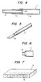
- Fig. 4 shows Embodiment 1 of the freely elongatable two-stage type of pipe.
- the larger-diameter pipe member 11 has a diameter a little smaller at one end portion 11a thereof than that of the other portion 11b.
- the freely elongatable two-stage type of sucking pipe shown in Fig. 1 or Fig. 2 consists of a larger-diameter pipe member and a smaller-diameter pipe member which are different slightly in their diameters only, and is apt to be judged as if it were composed of a single pipe member.
- Different colors are selected for the larger-diameter pipe member and smaller-diameter pipe member.
- the larger-diameter pipe member 11 and smaller-diameter pipe member 12 shown in Fig. 5 are colored, for example, red and white respectively.
- Fig. 6 shows the portion to be formed (socket portion) 11a of the larger-diameter pipe member selected here as an object to be formed.
- Fig. 7 shows an assembly 15 of metallic molds 16 to be used for forming the socket portion 11a of the larger-diameter pipe member 11.
- Each metallic mold 16 has a vacant space for containing the larger-diameter pipe member 11 and is so constructed as to form the socket portion 11a.
- the assembly 15 of the metallic molds may be used in a plural number as occasion demands.
- Fig. 8 shows a plan view illustrating the continuous forming process wherein larger-diameter pipe members 11 as objects to be formed are arranged at definite intervals on a conveyor 17.
- Reference numeral 15 denotes the assembly of the metallic molds shown in Fig. 7 which is arranged along the conveyor 17 on the side for shaping the larger-diameter pipe members 11.
- This assembly 15 of the metallic molds is shifted in the direction indicate by the arrow B which is the same as the travelling direction A of the conveyor 17 and at the same speed as the travelling speed of the conveyor 17 and, at the same time, in the direction indicated by the arrow C. That is to say, the assembly 15 of metallic molds is shifted in the direction determined as a composite of the shifting at the same speed as that of the conveyor 17 in the direction indicated by arrow B and shifting at an optional speed in the direction indicated by the arrow C.
- the assembly 15 of metallic molds advances in the direction indicated by the arrow C, i.e., approaches toward the larger-diameter pipe members 11, for example, represented by the reference numeral 18 in Fig.
- each of the larger-diameter pipe member within the range indicated by the reference numeral 18 is brought into close contact with each metallic mold 16 of the assembly 15.
- stopper members on the conveyor it is preferable to provide stopper members on the conveyor to prevent the larger-diameter pipe members from being deviated. While each of the larger-diameter pipe member is shifted for a definite time (definite distance) in the condition kept in close contact with each metallic mold 16, one end of each pipe member 11 is formed into a socket-like shape as shown in Fig. 6.
- the assembly 15 of metallic molds is shifted in the direction indicated by the arrow B at the same speed (as the shifting speed of the conveyor 17) and, at the same time, in the direction opposite to that indicated by the arrow C. That is to say, the assembly 15 performs shifting determined as a composite of the shifting in the direction indicated by the arrow B and shifting in the direction opposite to that indicated by the arrow C. By this shifting, the assembly 15 of metallic molds separates from the larger-diameter pipe members 11.
- clamp members which serve for fixing the larger-diameter pipe members 11 to the conveyor 17 in order to prevent the larger-diameter pipe members from adhering to the metallic molds 16 and shifting in directions deviating from the conveyor 17.
- the assembly 15 of metallic molds When the assembly 15 of metallic molds separates for a certain distance from the conveyor 17 or larger-diameter pipe members 11, it is shifted in the direction opposite to that indicated by the arrow B for circulation along a track. At this stage, the assembly 15 of metallic molds may be shifted not in the direction opposite to that indicated by the arrow C but straight in the direction opposite to that indicated by the arrow B. Alternately, the assembly 15 of metallic molds may be shifted in the direction determined as a composite of shifting in the direction opposite to that indicated by the arrow B and shifting in the direction opposite to that indicated by the arrow C.
- One cycle of the assembly 15 of metallic molds completes as described above. Then the assembly repeats the same cycle.
- a single or plural number of the assembly 15 of metallic molds may be circulated to bring each of the plural number of the larger-diameter pipe members within the range indicated by the reference numeral 19 into close contact with each metallic mold 16 for forming the socket-like shape on said larger-diameter pipe member.
- the larger-diameter pipe members are shaped consecutively in a unit of plural numbers (within the ranges indicated by the reference numerals 18 and 19 in Fig. 8) without stopping their shifting.
- independent metallic molds may be adopted in place of the above-mentioned assembly 15 of metallic molds.
- the Embodiment is applicable to other processes, for example, to form the expanded portions on the larger-diameter pipe members shown in Fig. 1 or Fig. 4, to cut off pipe members and form slits in pipe members.
- Fig. 9 and Fig. 10 show diagrams illustrating a package containing the freely elongatable two-stage type of sucking pipe.
- Fig. 9 shows a longitudinal sectional view of the package
- Fig. 10 shows a sectional view taken along the X-X line of Fig. 9.
- the reference numeral 10 represents the freely elongatable two-stage type of sucking pipe having the form shown in Fig. 1
- the reference numeral 21 designates a film A made of synthetic resin (or paper, etc.) having a step 21a which corresponds to the step between the larger-diameter pipe member 11 and smaller-diameter pipe member 12 of said freely elongatable two-stage type of sucking pipe 10.
- the reference numeral 22 denotes a film B made of a symthetic resin (or paper, etc.) having a slight downward swelling.
- the reference numeral 23 represents a horizontal seal portion formed by sealing the film A 21 and film B 22 at their edges by a means such as thermo-welding, and the reference numeral 24 designates a vertical seal portion obtained by the similar means.
- Fig. 9 and Fig. 10 are shown upside down, illustrating the film A 21 at the upper position and the film B 22 at the lower position.
- either of the film A 21 or film B 22 may be welded or bonded to beverage vessels for attaching the sucking pipe. Further, it is desirable to select a form having the step 21a as shown in Fig. 9 in packing the freely elongatable two-stage type of sucking pipe since such a form allows close contact between the films and freely elongatable two-stage type of sucking pipe on almost all the outer circumference of said pipe.
- the step 21a may not be tapered as shown in Fig. 9 but may be bent downward perpendicularly to the top surface.
- the film B 22 may also have a step corresponding to that of the freely elongatable two-stage type of sucking pipe.
- Fig. 11 and Fig. 12 show a holding block to be used for manufactureing the package.
- Fig. 11 shows a longitudinal sectional view of the holding block
- Fig. 12 shows a sectional view taken along the XII-XII line in Fig. 11.
- the holding block 25 has a concave groove 26 on the bottom surface of which a step is formed by providing a tapered surface 26c between a surface 26a and another surface 26b.
- Fig. 13 shows the freely elongatable two-stage type of sucking pipe inserted and packed in the concave groove 26 of the holding block 25.
- the film A 21 is arranged along the inside surface of the concave groove 26 of the holding block 25.
- the freely elongatable two-stage type of sucking pipe is placed in such a position that the smaller-diameter pipe member 12 is located on the side of the bottom surface 26a of the concave groove 26.
- the film B 22 is set over the sucking pipe, and finally the films A and B are welded to each other by thermo-welding around the concave groove 26 of the holding block 25.
- the package of the freely elongatable two-stage type of sucking pipe is prepared as described above.
- Inclination angle ⁇ of the tapered surface 26c formed in the concave groove of the holding block may have an optional value.
- Form of the step 21a of the film A 21 of the package is determined in accordance with value of the angle ⁇ .
- value of step d between the bottom surfaces 26a and 26b should desirably be set at a suitable level on the basis of difference between diameters of the larger-diameter pipe member and smaller-diameter pipe member.
- the package shown in Fig. 9 or Fig. 10 has swellings on the upper and lower sides, either of these sides may be bonded with high workability to beverage vessels, etc. for attaching the sucking pipe. Further, the package is advantageous in that it assures close contact between the films and freely elongatable two-stage type of sucking pipe at the packing stage.
- Fig. 14 shows a perspective view illustrating another embodiment of the package (upside down as compared with the example in Fig. 2).
- the reference numerals 31 and 32 represent lower film and upper film (described also later respectively) respectively made of synthetic resin materials
- the reference numeral 33 designates a cavity formed in the lower film by the process described later for enclosing a sucking pipe
- the reference numeral 34 denotes sealed portion (slashed portion) formed by welding the upper and lower films by the thermo-welding or the similar means
- the reference numeral 35 represents another welded spot.
- the package 30 accommodating thus formed pipe in each cavity is arranged successively to form a continuous belt.
- This continuous belt of the packages are cut off along the line 36 for separation into individual packages to be practically used in the condition, for example, shown in Fig. 3 to be attached to beverage vessels. Since each package 30 contains a rod-like body in the cavity 33 as described above and completely sealed at its periphery, the pipe is kept in sealed condition and free from fear of liquid penetration.
- Fig. 15 shows a perspective view illustrating a third embodiment of the package.
- welded spots 34 are formed within the areas (slashed areas) around the cavities 33 for accommodating the pipes and very close thereto, and welded spots are arranged further around said welded spots.
- the continuous belt is cut off along the intermediate line 37 between the cavities 33 for separation into the individual packages.
- the pipes are sealed with the welded spots 34 formed in the areas close to the cavities 33 and free from fear of liquid penetration.
- the Embodiment 2 allows users to easily take out the rod-like bodies from the packages by pushing one end of said rod-like bodies since no welded spots are formed in areas very close to said pipes.
- sealing may be incomplete depending on deviation of cutting lines in separating the continuous film into the individual packages by cutting said continuous belt.
- sealing of the pipes cannot be incomplete even when cutting lines are deviated a little in cutting the continuous belt into the individual packages.
- Fig. 16 and Fig. 17 show diagrams illustrating a part of a machine for carrying out the above-described manufacturing method of the continuous belt.
- Fig. 16 show a perspective view
- Fig. 17 shows a sectional view taken along the shifting direction of the metallic molds.
- the reference numeral 41 represents the metallic molds shifting successively
- the reference numeral 42 designates the cavities formed at the centers of the individual metallic molds
- the reference numeral 43 denotes convexities formed around the top surfaces of the individual metallic molds
- the reference numeral 44 represents spot-like convexities formed in multiple numbers between the cavity 42 and convexity 43 on top surface of each metallic mold
- the reference numeral 45 designates a heating roller having a smooth surface.
- the metallic molds 41 are shifted leftward as indicated by arrows in the drawings.
- the lower film 31 is first fed to the top surfaces of the metallic molds and shifted together with the metallic molds 41 in the direction indicated by the arrow.
- the film is attracted in heated condition to the cavity 42 with an attracting device (not shown), whereby the lower film adheres to the cavity 42. That is to say, the cavity 33 is formed as shown in Fig 14.
- the pipe 10 is supplied into cavity 42 of the metallic mold (cavity 33 of the film), and at the point C, the upper film 32 is supplied so as to cover the lower film 31.
- a pipe is completely sealed and is free from the fear of liqued penetration since the welded spots are formed in the area surrounding the cavity accommodating said pipe.
- the packing method carried out by the equipment according to the present invention easily permits forming the continuous belt of the packages with the packing machine described below since the cavities and the convexities around said cavities are formed on the metallic molds, and welded spots are formed by welding the films with the metallic molds and the heating roller.
- Fig. 18 shows a side view illustrating the overall construction of the continuous inspection-packing equipment according to the present invention.
- the reference numeral 50 represents a combining machine for automatically preparing the freely elongatable two-stage type of pipe shown in Fig. 4 by combining the larger-diameter pipe member with the smaller-diameter pipe member.
- the socket-like portion 11a is formed at the forming process shown in Fig. 8 on the larger-diameter pipe member 11 and the expanded portion 12a is formed on the smaller-diameter pipe member 12 in the process to push the end of the smaller-diameter pipe member 12 against a heated plate.
- the reference numeral 60 designates an automatic product inspection line
- the reference numeral 80 denotes a lack part replenish line
- the reference numeral 90 represents an automatic packing line
- the reference numeral 110 designates a winding line.
- the freely elongatable two-stage type of pipe prepared with the combining machine 50 is shifted in a condition mounted on a conveyor of the automatic product inspection line 60.
- said pipe is inspected for fitted condition of the smaller-diameter pipe member in the larger-diameter pipe member and defective pipe members are removed from the line.
- a freely elongatable two-stage type of pipe is replenished from the lack part replenish line.
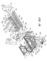
- Fig. 19 shows a perspective view of the automatic product inspection line.
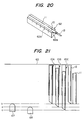
- the reference numeral 61 represents a first conveyor of multiple holding blocks 62 (see Fig. 20) having concave grooves 62a into which the freely elongatable two-stage type of pipes 10 are to be set and held
- the reference numeral 63 designates a brush roller consisting of a roller drum planted with brush hairs and arranged in the vicinity of start point of the conveyor 61.
- This brush roller 63 is provided for dropping off or removing, from the automatic product inspection line, pipes which are not inserted into the concave grooves 62a for some cause including those which were not inserted into the concave grooves 62a of the holding blocks 62 because the smaller-diameter pipe members were not inserted into the larger-diameter pipe members by the combining machine 50.
- the reference numeral 64 denotes a guide plate and the reference numeral 65 represents a gauge plate. These plates serve for aligning all the freely elongatable two-stage type of pipes reaching the location of the gauge plate 65 in such positions that their ends are kept in contact with the gauge plate 65 during shifting.
- the reference numeral 66 represents a pipe clamp belt having a construction in which a spring or round rope 66a passes around rollers 66b and 66c
- the reference numeral 67 designates a first compressor for pushing the smaller-diameter pipe member 12 into the larger-diameter pipe member 11 with weak force
- the reference numeral 68 denotes a second compressor for pushing the smaller-diameter pipe member 12 into the larger-diameter pipe member under strong force
- the reference numeral 70 represents a defective product detector
- the reference numeral 71 designates a defective product detector circuit
- the reference numeral 72 denotes a solenoid valve arranged in the course of a tube 73 for supplying high-pressure air
- the reference numeral 74 represents a shute for removing defective products.
- the first compressor 67 has a compressing piece 67a which is urged by a built-in spring in the direction perpendicular to the shifting direction of the conveyor 61.
- the compressing piece 67a is restricted by a limiter 67b so that it will not project beyond a certain positon.
- Force of the spring urging the compressing piece 67a is adjusted to a suitable level by a spring pressure adjuster 67c.
- the second compressor 68 has the same construction as that of the first compressor 67, but force of the spring of the second compressor is adjusted by a spring pressure adjuster 68c to a level higher than that of the spring of the first compressor 67. Therefore, when the smaller-diameter pipe member 12 is fitted too tightly to move by the ordinary finger power relative to the larger-diameter pipe member 11, the compressing piece 68a is pushed back by the smaller-diameter pipe member 12. Further, the compressing piece 68a is restricted by a limiter 68b so that it will be project beyond a standard position.
- tips of the smaller-diameter pipe members are located at the standard position when the freely elongatable two-stage type of pipes are normal, inside the standard position when products have too loose fitting between the pipe members or outside the standard position when products have too tight fitting between the pipe members.
- the tips of the smaller-diameter pipe members are located at the standard position when the freely elongatable two-stage type of pipes are normal, whereas the tips of the smaller-diameter pipe members are not located at the standard position when the freely elongatable two-stage type of pipes are defective.
- Fig. 21 shows a diagram descriptive of a means for inspecting defective freely elongatable two-stage type of pipes described above.
- the reference numeral 10A represents a freely elongatable two-stage type of pipe in which the smaller-diameter pipe member is fitted too loose in the larger-diameter pipe member
- the reference numeral 10B designates a normal freely elongatable two-stage type of pipe
- the reference numeral 10c denotes a freely elongatable two-stage type of pipe having too tight fitting between the pipe members
- the reference numeral 11 represents a larger-diameter pipe member
- the reference numeral 12 designates a smaller-diameter pipe member. Shown in Fig.
- the smaller-diameter pipe member is pushed into the larger-diameter pipe member by the second compressor 68 and the tip of the smaller-diameter pipe member is located at the same position as that of the tip of the second compressor 68, or the standard position (indicated by the chain line a).
- the freely elongatable two-stage type of pipe 10C of too tight fitting has passed while pushing back both the first compressor 67 and second compressor 68. Accordingly, the tip of the smaller-diameter pipe member remains at the position before passing by the compressors, for example, that indicated by the chain line c. If the smaller-diameter pipe member 12 is not inserted into the larger-diameter pipe member 11, tip of the pipe is located at the position indicated by the chain line b or on the side of the gauge plate 65 from the chain line b.
- the defective product detector 70 is composed of a detecting piece 70a whose tip is lightly urged toward the conveyor 61 under force of a spring as shown in Fig. 19, a light shield plate 70c which has a slit and rotates together with said detecting piece 70a when it rotates around a shaft 70b, a photosensor composed of a light source 70d and a photosensor element 70e which are arranged on both sides of said light shield plate 70c.
- the freely elongatable two-stage type of pipe having passed by the first compressor 67 and second compressor 68 reaches the defective product detector 70, said pipe 10 pushes and rotates the detecting piece 70a, thereby allowing the photosensor to detect the shift of the light shield plate 70c rotating together with the detecting piece 70a.
- a signal is inputted to a defective product detector circuit 71 to inform whether or not the product is normal.
- shifting conditions of the holding blocks are detected (for example, the individual holding blocks are counted) and detection signals are inputted as standard signals into the defective product detector circuit 71 from a holding block shift detector which consists of a magnet embedded into each holding block 62 of the conveyor 61 and a magnetic sensor arranged in the vicinity of the conveyor 61, or a photo-sensor consisting of a light source and photosensor element arranged in the vicinity of the conveyor, said components of the detector being not shown.
- an operation pulse signal is generated from the defective product detector circuit 71, a highspeed solenoid valve 72 is opened to supply high-pressure air to the conveyor 61 and the air is supplied through a vent hole 62b of the holding block 62 containing the defective product to remove the defective freely elongatable two-stage type of pipe from the automatic product inspection line 60 through a discharge chute 74.
- the defective product is detected and removed from the line as described above.
- a pipe end thickening device (not shown) may be arranged before the lack part replenish device 80, i.e., at the location represented by the reference numeral 75 in Fig. 18 and Fig. 19.
- This pipe end thickening device is used for preventing the smaller-diameter pipe member from getting out of the larger-diameter pipe member by reducing the inside diameter at the end of the larger-diameter pipe member while heating the freely elongatable two-stage type of pipe at the end on the side of the gauge plate 65.
- the lack part replenishment device 80 consists of a hopper 81, a drum 82 having multiple grooves 82a, a conveyor 83 consisting of multiple holding blocks 84, and so on.
- the hopper is filled with freely elongatable two-stage type of pipes which are consecutively supplied into the grooves 82a of the drum 82 which rotates in the direction indicated by the arrow.
- the freely elongatable two-stage type of pipe set in the groove 82a is located at the lowermost position, it is forcibly dropped into the groove 84a of the holding block 84 of the conveyor 83 kept into contact with the drum 82 under the guide by the guide plates 82b and 82c.
- a freely elongatable two-stage type of pipe drops from the holding block 84 into the holding block 62 for replenishment.
- the holding block 84 containing no freely elongatable two-stage type of pipe any longer due to the replenishment is further shifted and located at the position brought into contact with the drum 82, said holding block 84 is replenished with the freely elongatable two-stage type of pipe from the groove 82a of the drum 82.
- the groove 82a containing no freely elongatable two-stage type of pipe any longer is replenished with a freely elongatable two-stage type of pipe from the hopper 81.
- the lack part replenish device supplies freely elongatable two-stage type of pipes without fail. Accordingly, any holding block reaching the automatic packing line 90 at the next stage does not contain a defective freely elongatable two-stage type of pipe or is kept empty.
- Freely elongatable two-stage type of pipes in the hopper 81 of the lack part replenish device are prepared as described below.
- the reference numeral 85 represents a guide plate for preventing the freely elongatable two-stage type of pipe from springing out of the groove 82a during rotation of the drum 82
- the reference numerals 86 and 87 designate also guide plates for the conveyor 83 and conveyor 61 respectively
- the reference numeral 88 denotes a blow air hopper for forcibly dropping freely elongatable two-stage type of pipes.
- the reference numeral 91 represents a conveyor consisting of multiple holding blocks 92 connected to one another.
- a lower film 93 is supplied onto the conveyor 91 by a first film feeding means by way of roller 94 arranged at a certain angle relative to the shifting direction of the conveyor 91 (for example 45°).
- the reference numeral 95 denoted a film attracting device which is communicated with a vacuum pump through a duct tube 96 and functions to attract the lower film 93 through an air vent formed in the holding block 92 of the conveyor 91 so that the lower film 93 adheres to the surface of the holding block 92 along the concave grooves 92a.
- the film may be heated with a heating means (not shown) before or during the attraction.
- the reference numeral 97 denotes a drum which is located under the end of the conveyor 61 as shown in Fig. 19 and serves for shifting the freely elongatable two-stage type of pipe carried by the conveyor 61 to the conveyor 91 of the automatic packing line 90.
- the freely elongatable two-stage type of pipe which has been carried in the groove 97a of the drum 97 is shifted to the groove 92a of the holding block 92.
- the lower film 93 has already been supplied to the conveyor 91 and adheres to the surface of the holding block 92 along the grooves 92a.
- the freely elongatable two-stage type of pipe is shifted from the drum 97 into the cavity of the lower film 93 formed along the groove 92a.
- an upper film is supplied onto the conveyor 91 by a second film feeding means via a roller arranged at a certain definite angle relative to the shifting direction of the conveyor.
- the reference numeral 100 represents a chain guide plate
- the reference numeral 101 designates a first sealer for welding the lower and upper films 93 and 98 to each other by heating at the sections between the freely elongatable two-stage type of pipes
- the reference numeral 102 denotes a second sealer for thermally welding the lower and upper films 93 and 98 to each other at their edges (outside the freely elongatable two-stage types of pipes)
- the reference numerals 103 represents a roller cutter for cutting off both the edged of the lower and upper films 93 and 98
- the reference numeral 104 designates a cover for protecting the entire packing line described above.
- the first and second sealers may be made integral so as to seal the films simultaneously in both the longitudinal and lateral directions.
- the individual freely elongatable two-stage type of pipes are packed between the upper and lower films so as to form a continuous belt by the automatic packing line described above, and shifted to the next winding line 110.
- the continuous belt of the packages passes under a roller 111 and over a roller 112, over an air floating conveyor 113, and attracted to a drum 114 to be described later, thereafter being sent by rotation of said drum 114.
- the reference numeral 118 represents a chute revolving around the rotating shaft of the drum 114
- the reference numeral 121 designates a reel
- the reference numeral 122 denotes a bobbin hopper
- the reference numeral 123 represents a bobbin chute
- the reference numeral 124 designates a bobbin piston
- the reference numeral 125 denotes a bobbin insert piston
- the reference numeral 126 denotes a driving motor
- the reference numeral 127 represents a torque converter for rotating said bobbin by means of pulleys and a belt.
- the reference numeral 128 represents a piston for pushing out products and the reference numeral 129 designates a chute for sending the products wound around the bobbin.
- the continuous belt of the packages passes under the roller 111, over the roller 112, and then is floated up and shifted forward over the air floating conveyor 113. Then, the continuous belt of the packages is attracted to a package shifting drum 114 and carried.
- the drum 114 has a construction illustrated in Fig. 24A and Fig. 24B.
- the drum 114 has a double construction consisting of an inner drum 116 fixed to a hollow shaft 115 having a partition 115a at the center, and an outer drum 117 rotatably held around said inner drum 116 and having an air vent 117a.
- Air is aspirated from one end of the shaft 115 through the air vent 116a of the inner drum 116 and the air vent 117a of the outer drum 117. Further, air is supplied into the other end of the shaft 115, and exhausted through the air vents 116b and 117a.
- the continuous belt 105 of the packages is sent to the drum 114 as shown in Fig. 24B illustrating a sectional view taken along the B-B line of Fig. 24A, air above the drum 114 is aspirated through the air vent 117a to attract the continuous belt to the drum 114.
- the continuous belt 105 is sent when the outer drum 117 is rotated by a suitable means.
- the continuous belt 105 When the continuous belt 105 reaches the bottom of the drum 114, it is separated from the drum 114 by flow of the air exhausted through the air vents 116b and 117a.
- the continuous belt 105 is sent consecutively by rotation of the drum 114 while being attracted and separated, and then wound around the bobbin.
- the continuous belt When the continuous belt is wound fully around the bobbin, said continuous belt is cut off with a cutter 119.
- the product pushing piston 128 operates to push out the continuous belt from the reel 121 and send it to the belt conveyor 121.
- the tip of the chute 118 is always located on the outer circumference of the wound continuous belt at a position corresponding to the quantity of the wound continuous belt, and rotating speed and torque of the bobbin are controlled with the torque converter 117. Accordingly, the continuous belt is wound correctly.
- the next bobbin is supplied to the winding position by a bobbin insert piston 125. Since the bobbin located at the lowermost position is removed from the bobbin chute 123, all the other bobbins are dropped to set the bobbin chute ready for supplying a new bobbin once again. On the other hand, the tip of the subsequent continuous belt of packages reaches, after cutting, the bobbin located at the center of the reel 121 and the winding operation starts once again.
- the continuous belt of packages of the freely elongatable two-stage type of pipes is wound around a bobbin at a constant rate during continuous manufacturing, and carried by the belt conveyor 131.
- the equipment is placed in operating condition to supply freely elongatable two-stage type of pipes from the combining machine 50 to the first conveyor 61 of the automatic product inspection line 60.
- freely elongatable two-stage type of pipes which were not inserted into the concave grooves 62a of the holding blocks 62 are removed from the line by the brush roller 63 as already described above.
- the packing work is not carried out in the automatic packing line 90.
- the freely elongatable two-stage type of pipes only are shifted by the second conveyor 91 without feeding the lower film 93 or upper film 98. Since the freely elongatable two-stage type of pipes carried to the end point of the second conveyor 91 are dropped without being packed at the end point of the second conveyor 91. A container is placed at this point to accumulate the normal freely elongatable two-stage type of pipes.
- the equipment is stopped and the hopper 81 of the lack part replenish device is filled with the pipes.
- the freely elongatable two-stage type of pipes are shifted to the automatic packing line 90 and carried by the second conveyor 91.
- the lower film 93 and upper film 98 are supplied, and sealed by the first and second sealers 101 and 102.
- the continuous belt 105 of packages containing the freely elongatable two-stage type of pipes prepared by sealing the films is wound around a bobbin at a constant rate by the winding device arranged at the next stage, and carried by the belt conveyor.
- the holding block of the conveyor 91 in the automatic packing line 90 has the construction shown in Fig. 20, but is longer than the freely elongatable two-stage type of pipe in its condition shown in this drawing.
- the holding block 25 shown in Fig. 12 it is possible to prepare the continuous belt of packages shown in Fig. 9 or Fig. 10.
- the sealing roller 101 a roller having multiple concave grooves parallel to its shaft and preferably a attracting function.
- it is possible to taper the grooves of this roller so as to have a shape along the end portion 11a of the larger-diameter pipe member.
- the holding block 41 shown in Fig. 16 and Fig. 17 can be used as the holding block of the conveyor 91.
- the roller 45 having the smooth surface should be used as the sealing roller.
- the holding block and sealing roller shown in Fig. 16 and Fig. 17 are employed, it is possible to automatically prepare a continuous belt of packages shown in Fig. 14 or Fig. 15.
- the continuous inspection-packing equipment according to the present invention described above uses no hopper for the component units other than the lack part replenish device, and supplies pipes without fail since it inspects and packs freely elongatable two-stage type of pipes fed into the line immediately from a molding-combining machine. Further, the continuous inspection-packing equipment according to the present invention does not set defective or no products in packages since it inspects freely elongatable two-stage type of pipes during carriage. Moreover, said continuous inspection-packing equipment is rarely troubled and easily adjustable since it adopts the rollers and drums in the smallest possibe numbers.
Landscapes
- Engineering & Computer Science (AREA)
- Mechanical Engineering (AREA)
- Chemical & Material Sciences (AREA)
- Composite Materials (AREA)
- Containers And Plastic Fillers For Packaging (AREA)
- Rigid Pipes And Flexible Pipes (AREA)
Claims (1)
- Machine d'emballage avec contrôle continu présentant une chaîne de contrôle automatisé des produits (60) comprenant un premier convoyeur (61) consistant en une pluralité de blocs de maintien (62) présentant des rainures concaves (62a) et portant des tubes à deux étages librement téléscopiques (10) formés de tubes de grand diamètre (11) et de tubes de petit diamètre (12) placés dans lesdites rainures concaves (62a), un premier et un deuxième compresseurs (67, 68) disposés à côté du premier convoyeur (61) et de puissances différentes pour compresser, ou être compressés par, l'extrémité de l'un des deux tubes (11, 12), un mécanisme de détection (70) permettant de juger si un produit est normal ou défectueux en détectant les positions des extrémités de l'un des deux tubes (11, 12) formant le tube à deux étages librement téléscopique (10) lorsqu'ils ont passé à côté desdits premier et deuxième compresseurs (67, 68), un mécanisme de mise à l'écart des produits défectueux fonctionnant lorsqu'il y a détection d'un produit défectueux par ledit mécanisme de détection (70), et un dispositif de recharge en pièces manquantes (80) permettant de placer des tubes à deux étages librement téléscopiques (10) inspectés dans des blocs de maintien (62) ne contenant pas de tubes à deux étages librement téléscopiques (10), et une chaîne d'emballage automatisée (90) comprenant un deuxième convoyeur (91) composé de blocs de maintien (92) connectés les uns aux autres, des premiers et deuxièmes moyens d'alimentation en pellicule pour la fourniture de pellicules inférieure et supérieure (93, 98) audit deuxième convoyeur, et un dispositif à sceller (101, 102), et fonctionnant pour alimenter en tubes à deux étages librement téléscopiques (10) les blocs de maintien (92) dudit deuxième convoyeur (91) à partir de ladite chaîne de contrôle automatisé des produits (60) à un endroit situé entre lesdits premiers moyens d'alimentation en pellicule et lesdits deuxièmes moyens d'alimentation en pellicule, pour recouvrir lesdits tubes (10) avec ladite pellicule (98) et souder ensuite lesdites pellicules (93, 98) l'une à l'autre avec ledit dispositif à sceller (101, 102).
Applications Claiming Priority (6)
| Application Number | Priority Date | Filing Date | Title |
|---|---|---|---|
| JP81310/83U | 1983-05-31 | ||
| JP8131083U JPS59186282U (ja) | 1983-05-31 | 1983-05-31 | 飲料容器への接着用ストロー包装体 |
| JP11716283A JPS6013614A (ja) | 1983-06-30 | 1983-06-30 | 棒状体の包装装置 |
| JP117162/83 | 1983-06-30 | ||
| JP199472/83U | 1983-12-28 | ||
| JP19947283U JPS60108881U (ja) | 1983-12-28 | 1983-12-28 | 二段式伸縮自在な吸引用パイプ |
Related Parent Applications (1)
| Application Number | Title | Priority Date | Filing Date |
|---|---|---|---|
| EP84106133.6 Division | 1984-05-29 |
Publications (3)
| Publication Number | Publication Date |
|---|---|
| EP0276025A2 EP0276025A2 (fr) | 1988-07-27 |
| EP0276025A3 EP0276025A3 (en) | 1988-09-28 |
| EP0276025B1 true EP0276025B1 (fr) | 1992-01-29 |
Family
ID=27303554
Family Applications (2)
| Application Number | Title | Priority Date | Filing Date |
|---|---|---|---|
| EP19880101820 Expired EP0276025B1 (fr) | 1983-05-31 | 1984-05-29 | Machine d'emballage avec contrôle continu |
| EP84106133A Expired EP0127178B1 (fr) | 1983-05-31 | 1984-05-29 | Corps en forme de barre |
Family Applications After (1)
| Application Number | Title | Priority Date | Filing Date |
|---|---|---|---|
| EP84106133A Expired EP0127178B1 (fr) | 1983-05-31 | 1984-05-29 | Corps en forme de barre |
Country Status (2)
| Country | Link |
|---|---|
| EP (2) | EP0276025B1 (fr) |
| DE (3) | DE3485496D1 (fr) |
Families Citing this family (7)
| Publication number | Priority date | Publication date | Assignee | Title |
|---|---|---|---|---|
| SE463970B (sv) * | 1987-03-24 | 1991-02-18 | Roby Teknik Ab | Sugroersfoerpackning |
| US5776860A (en) * | 1993-02-26 | 1998-07-07 | Nippon Zeon Co., Ltd. | Plant growth promoter |
| CN105231769A (zh) * | 2015-10-19 | 2016-01-13 | 常州市武进亚太机电配件有限公司 | 复合型食用吸管 |
| DE102019104588A1 (de) * | 2019-02-22 | 2020-08-27 | 5G Investment GmbH & Co. KG | Längenveränderlicher Trinkhalm |
| EP3903649A1 (fr) | 2020-04-28 | 2021-11-03 | International Tobacco Machinery Poland SP. Z O.O. | Appareil d'assemblage de pailles télescopiques et procédé d'assemblage de pailles télescopiques |
| EP3904242A1 (fr) | 2020-04-28 | 2021-11-03 | International Tobacco Machinery Poland SP. Z O.O. | Appareil de déplacement longitudinale d'articles en forme de tige |
| PL244693B1 (pl) * | 2021-03-24 | 2024-02-26 | Int Tobacco Machinery Poland Spolka Z Ograniczona Odpowiedzialnoscia | Urządzenie oraz sposób korygowania kształtu krawędzi rurek |
Family Cites Families (10)
| Publication number | Priority date | Publication date | Assignee | Title |
|---|---|---|---|---|
| DE1179499B (de) * | 1960-01-29 | 1964-10-08 | Schmermund Maschf Alfred | Einrichtung zum Austauschen mangelhaft gefuellter gegen einwandfrei gefuellte Packungen, insbesondere an einer Zigarettenpackmaschine |
| GB904010A (en) * | 1960-12-07 | 1962-08-22 | Yat Chuen Yuen | Improvements in or relating to drinking straws and drinking appliances |
| DE1912368A1 (de) * | 1968-04-30 | 1969-11-20 | Magyar Vagon Es Gepgyar | Schmieranordnung fuer Fahrzeuglaufwerke |
| IT1161654B (it) * | 1978-04-18 | 1987-03-18 | Cir Spa Divisione Sasib | Dispositivo per il rimpiazzo automatico dei pacchetti scartati da una linea di alimentazione regolare |
| JPS601206B2 (ja) * | 1979-07-11 | 1985-01-12 | テトラ パツク インタ−ナシヨナル アクチボラグ | フィルムによる棒状物の包装装置 |
| IT8000606A0 (it) * | 1980-01-30 | 1980-01-30 | Claudio Concetti | Nastro di cannucce da bibite |
| IT1133263B (it) * | 1980-04-01 | 1986-07-09 | Gd Spa | Dispositivo di controllo dell'integrita' delle sigarette in una macchina impacchettatrice |
| US4340175A (en) * | 1980-04-17 | 1982-07-20 | Ladislav Danek | Mechanical straw pencil |
| FR2488213A1 (fr) * | 1980-08-06 | 1982-02-12 | Soyez Freres Sa | Dispositif pour fabriquer une nappe constituee de deux bandes enfermant entre elles une serie de tubes transversaux |
| EP0139074A3 (fr) * | 1983-04-11 | 1985-06-05 | Sanyo Shiki Kabushiki Kaisha | Chalumeau pour boire, télescopique |
-
1984
- 1984-05-29 EP EP19880101820 patent/EP0276025B1/fr not_active Expired
- 1984-05-29 DE DE8888101820T patent/DE3485496D1/de not_active Expired - Lifetime
- 1984-05-29 EP EP84106133A patent/EP0127178B1/fr not_active Expired
- 1984-05-29 DE DE8484106133T patent/DE3477728D1/de not_active Expired
- 1984-05-29 DE DE1988101820 patent/DE276025T1/de active Pending
Also Published As
| Publication number | Publication date |
|---|---|
| DE3477728D1 (en) | 1989-05-24 |
| EP0127178A3 (en) | 1985-07-24 |
| EP0276025A2 (fr) | 1988-07-27 |
| EP0127178A2 (fr) | 1984-12-05 |
| DE3485496D1 (de) | 1992-03-12 |
| DE276025T1 (de) | 1989-01-05 |
| EP0127178B1 (fr) | 1989-04-19 |
| EP0276025A3 (en) | 1988-09-28 |
Similar Documents
| Publication | Publication Date | Title |
|---|---|---|
| CN101541262B (zh) | 用精液填充人工受精吸管的机器 | |
| US7891395B2 (en) | Procedure and device for sticking objects | |
| US4643027A (en) | Apparatus for testing cigarette packs and the like | |
| EP0276025B1 (fr) | Machine d'emballage avec contrôle continu | |
| JPS6013629A (ja) | 容器にバンド様物体をはりつけるための装置 | |
| JP2006219203A (ja) | 製品取りまとめ自動装置 | |
| GB2031263A (en) | Method and apparatus for pinpointing the causes of malfunction of machines for the manufacture and/or processing of cigarettes or the like | |
| JP4105167B2 (ja) | 紙巻きタバコパック開封および紙巻きタバコ検査用の装置 | |
| KR20100087282A (ko) | 권취 장치 및 권취 장치를 구비하는 조립체 | |
| CZ329498A3 (cs) | Připevňovací zařízení pro připevňování brček a způsob připevňování | |
| US5155967A (en) | Automated bag manufacturing and packaging system | |
| US5473862A (en) | Method and a device for joining the component wrappers of divisible packs containing several single packets of cigarettes | |
| DK3110696T3 (en) | DEVICE AND PROCEDURE FOR MANUFACTURING PORTION PACKAGES OF A SMOKED TOBACCO OR TOBACCO NOFT | |
| US5476354A (en) | Method and apparatus for opening soft-cup cigarette packs | |
| EP1170213A1 (fr) | Dispositif d' alimentation d' articles à une bande alvéolaire | |
| EP1176106B1 (fr) | Procédé et système pour la préparation automatisée de prises de médicaments à partir d'ordonnances informatisées | |
| JP7542022B2 (ja) | ブリスタ包装機 | |
| JPH07329916A (ja) | 割り箸包装装置 | |
| JPS6013614A (ja) | 棒状体の包装装置 | |
| US4245934A (en) | Conveying rod-like articles | |
| US4911028A (en) | Apparatus and method for carrying out measurements on a bobbin of sheet material | |
| JP2002211508A (ja) | 卵包装装置及び卵自動選別システム | |
| US5974769A (en) | Automated container insert device | |
| US4334487A (en) | Method of manufacturing composite containers | |
| JPH08334477A (ja) | 写真フイルムパトローネのフレキシブルディスクの検査方法及び装置 |
Legal Events
| Date | Code | Title | Description |
|---|---|---|---|
| PUAI | Public reference made under article 153(3) epc to a published international application that has entered the european phase |
Free format text: ORIGINAL CODE: 0009012 |
|
| 17P | Request for examination filed |
Effective date: 19880208 |
|
| AC | Divisional application: reference to earlier application |
Ref document number: 127178 Country of ref document: EP |
|
| AK | Designated contracting states |
Kind code of ref document: A2 Designated state(s): DE FR GB IT LU |
|
| PUAL | Search report despatched |
Free format text: ORIGINAL CODE: 0009013 |
|
| AK | Designated contracting states |
Kind code of ref document: A3 Designated state(s): DE FR GB IT LU |
|
| RIN1 | Information on inventor provided before grant (corrected) |
Inventor name: MIZUSHIMA, KYOHEI Inventor name: HOSHI, KATSUMASA |
|
| DET | De: translation of patent claims | ||
| 17Q | First examination report despatched |
Effective date: 19901001 |
|
| GRAA | (expected) grant |
Free format text: ORIGINAL CODE: 0009210 |
|
| AC | Divisional application: reference to earlier application |
Ref document number: 127178 Country of ref document: EP |
|
| AK | Designated contracting states |
Kind code of ref document: B1 Designated state(s): DE FR GB IT LU |
|
| ITF | It: translation for a ep patent filed | ||
| REF | Corresponds to: |
Ref document number: 3485496 Country of ref document: DE Date of ref document: 19920312 |
|
| ET | Fr: translation filed | ||
| PGFP | Annual fee paid to national office [announced via postgrant information from national office to epo] |
Ref country code: FR Payment date: 19920430 Year of fee payment: 9 |
|
| PGFP | Annual fee paid to national office [announced via postgrant information from national office to epo] |
Ref country code: LU Payment date: 19920506 Year of fee payment: 9 |
|
| EPTA | Lu: last paid annual fee | ||
| PLBE | No opposition filed within time limit |
Free format text: ORIGINAL CODE: 0009261 |
|
| STAA | Information on the status of an ep patent application or granted ep patent |
Free format text: STATUS: NO OPPOSITION FILED WITHIN TIME LIMIT |
|
| 26N | No opposition filed | ||
| PG25 | Lapsed in a contracting state [announced via postgrant information from national office to epo] |
Ref country code: LU Free format text: LAPSE BECAUSE OF NON-PAYMENT OF DUE FEES Effective date: 19930529 |
|
| PGFP | Annual fee paid to national office [announced via postgrant information from national office to epo] |
Ref country code: DE Payment date: 19930602 Year of fee payment: 10 |
|
| PG25 | Lapsed in a contracting state [announced via postgrant information from national office to epo] |
Ref country code: FR Effective date: 19940131 |
|
| REG | Reference to a national code |
Ref country code: FR Ref legal event code: ST |
|
| PG25 | Lapsed in a contracting state [announced via postgrant information from national office to epo] |
Ref country code: DE Effective date: 19950201 |
|
| PGFP | Annual fee paid to national office [announced via postgrant information from national office to epo] |
Ref country code: GB Payment date: 19960520 Year of fee payment: 13 |
|
| PG25 | Lapsed in a contracting state [announced via postgrant information from national office to epo] |
Ref country code: GB Effective date: 19970529 |
|
| GBPC | Gb: european patent ceased through non-payment of renewal fee |
Effective date: 19970529 |