EP0276056A2 - Agencement de vanne pour système de commande de débit de fluide - Google Patents
Agencement de vanne pour système de commande de débit de fluide Download PDFInfo
- Publication number
- EP0276056A2 EP0276056A2 EP88300104A EP88300104A EP0276056A2 EP 0276056 A2 EP0276056 A2 EP 0276056A2 EP 88300104 A EP88300104 A EP 88300104A EP 88300104 A EP88300104 A EP 88300104A EP 0276056 A2 EP0276056 A2 EP 0276056A2
- Authority
- EP
- European Patent Office
- Prior art keywords
- fluid
- valve
- spool
- pressure
- flow
- Prior art date
- Legal status (The legal status is an assumption and is not a legal conclusion. Google has not performed a legal analysis and makes no representation as to the accuracy of the status listed.)
- Withdrawn
Links
Images
Classifications
-
- G—PHYSICS
- G05—CONTROLLING; REGULATING
- G05D—SYSTEMS FOR CONTROLLING OR REGULATING NON-ELECTRIC VARIABLES
- G05D16/00—Control of fluid pressure
- G05D16/20—Control of fluid pressure characterised by the use of electric means
- G05D16/2093—Control of fluid pressure characterised by the use of electric means with combination of electric and non-electric auxiliary power
- G05D16/2097—Control of fluid pressure characterised by the use of electric means with combination of electric and non-electric auxiliary power using pistons within the main valve
Definitions
- valve arrangements have been used to control fluid flow to a fluid responsive actuator, such as a clutch or brake mechanism in a vehicle transmission.
- a fluid responsive actuator such as a clutch or brake mechanism in a vehicle transmission.
- One known approach includes the use of a two stage valve assembly including a servo valve wherein an electrical input signal causes a displacement of a valve component in a precise manner.
- a two stage valve assembly using an on-off solenoid valve in one stage and a freely mounted spool in its second stage was disclosed in U.S. patent 4,116,321, granted September 26, 1978. Rather than controlling flow, this patented apparatus was concerned with pressure regulation. With the patented apparatus, the valve output flow was not proportional to the control signal but to the integral of the control signal. Accordingly, it could not be operated open loop. Instead, the patented apparatus must be used in a closed loop system.
- valve disclosed in the '321 patent is functionally equivalent to an integrator it always has a 90° phase lag. When used in an application when the system to be controlled has a substantial amount of time lag, it may be difficult to stabilize the control with a single feed back loop.
- a control system for regulating fluid flow to a fluid responsive actuator.
- the system includes a two stage valve assembly wherein one stage includes a pressure responsive spool with resilient feedback means for regulating fluid flow between a fluid source or supply and the fluid responsive actuator as a function of the spool's linear position.
- the linear position of the spool being determined by oppositely directed pressure based position determining forces one of which may predominate over the other.
- the other stage of the valve assembly includes an on-off solenoid valve for controlling one position determining force. The use of an on-off solenoid valve enables the valve assembly to produce a linear proportional fluid flow output.
- a pulse width modulated (PWM) circuit has its output coupled to the solenoid valve winding.
- the PWM circuit is capable of providing an alternating output signal of which the duty cycle may be varied to effect the position of the spool and thereby the flow to the actuator.
- the valve assembly of the present invention is a time lag element instead of an integrator. As such, the valve assembly offers to the control system less phase lag than an integrator at lower frequency. The time lag or bandwidth depends on the valve design which can be modified to suit particular applications.
- a primary object of this invention is the provision of an improved control system for regulating fluid flow between a fluid supply source and a fluidically responsive actuator such as that used in vehicle transmission systems.
- Another object of this invention is the provision of a control system which provides the advantages of a servo type valve but at considerably less cost.
- Still another object of this invention is the provision of a control system having a two stage valve assembly which uses an on-off solenoid to produce linear proportional output from the valve assembly which is obtainable only so far with servo valves.
- the invention comprises the devices, combination and arrangement of parts as illustrated in the presently preferred form of the invention which are hereinafter set forth in detail to enable those skilled in the art to readily understand the function, operation, construction and advantages of same when read in conjunction with the accompanying drawing in which:
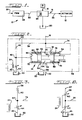
- FIG. 1 schematically illustrates a control system 10 for regulating the operation of a hydraulic device 12.
- the device 12 can be a movable sheave in a CVT transmission, or any unit which responds as a function of the amount of fluid flow thereto.
- a salient feature or component of the control system is the provision of a control valve assembly 14 for modulating fluid flow between a fluid source 16 and the hydraulic actuator 12.
- the fluid source may be in the form of a pump or other fluid supply unit.
- the valve assembly is adapted to receive fluid under pressure from the fluid source 16 over line 18.
- the valve assembly has a plurality of outlets. One or more of these outlets drain fluid to a sump or reservoir 20. Another outlet is connected over line 22 to the actuator 12.
- the valve assembly 14 also includes a winding 24 which is effective to vary effective fluid flow through an orifice.
- the control system 10 of the present invention is open loop.
- a preselected control signal is applied over line 26 to a Pulse Width Modulation (PWM) stage 28 of the control system.
- PWM Pulse Width Modulation
- This can be a free running multivibrator or voltage controlled oscillator of the type in which the period is constant but the duty cycle is regulated by a potentiometer or other modulatable controller (not shown).
- PWM stage 28 Such stages as PWM stage 28 are well known and understood in this art.
- the output square - wave signal with a controlled or predetermined duty cycle is applied over line 30 to winding 24 of valve 14.
- FIG. 2 is a schematic representation of the two stage valve assembly 14.
- a fluid under pressure is received at intake port 32 of the valve assembly over line 18 and fluid may be discharged from the valve assembly to the sump through output ports 34 and 36.
- the supply line pressure is passed through lines 18 and 38, through a first orifice 40 in a pilot or first stage 42 of the valve assembly, and thence through a second orifice 44.
- the fluid passing through the orifice 44 is drained to the sump 20 over line 45.
- the flow rate through orifice 44 is regulated by the signal received on winding 24.
- Orifices 40 and 44 are coupled together at a common point or junction 46 and this point represents a constant pressure point in the valve assembly 14.
- Stage 48 of the valve assembly is a flow control stage because it controls the flow over line 22 to the actuator 12 as a function of spool postion, to operate a unit such as a movable sheave in a CVT transmission.
- Stage 48 of the valve assembly 14 includes a closed center spool or closure member 50 which is slidably arranged or accomodated in an elongated slideway 52 provided in a body portion 54 of the valve assembly.
- the spool or valve means regulates the fluid flow between intake port 32 and, in the illustrated embodiment, either of two axially spaced output orifices 34 and 36.
- stage 48 is a three-way arrangement although additional ports could easily be added without distracting from the spirit and scope of the invention.
- the return orifice 34 leads or is connected to line 56 which delivers fluid to sump 20 while output orifice 36 leads or is connected to line 22 leading to the actuator 12.
- the valve spool is shown as having lands 58 and 60 which are connected by a stem 62 of comparatively smaller diameter.
- an annular space 64 surrounds the stem so as to permit communication of orifice 36 with either the input port 32 or the return port 34 depending on the relative position of lands 58 and 60.
- the opposing end faces of lands 58 and 60 preferably have square outer annular corners and substantially flat sides.
- the end faces of the lands 58 and 60 have the same axial spacing as that between return port 34 and outlet port 36.
- a hydraulic pressure system is included within the valve assembly for controlling the position of the valve means 50 and thereby the flow at the control fluid port 36.
- This hydraulic system includes fluidic means which communicate with the fluid supply source and act to apply oppositely directed position determining forces against the opposite ends of the spool or valve means 50.
- fluidic means includes end chambers 66 and 68 which, in the illustrated embodiment are lateral extensions of the slideway 52 arranged in the valve body 54.
- Stage 48 of valve assembly 14 further includes mechanical resilient means 70 and 72 defining resilient feedback means for the valve assembly.
- the mechanical resilient means 70 and 72 comprise compression springs disposed in each end chamber, with the ends of each spring impinging against an end wall of the end chamber and a spool end. Each end chamber is adapted to receive input fluid under pressure.
- fluid under supply pressure is passed over line 74 to end chamber 68 wherein it establishes a fluid pressure against end surface 76 of spool 50.
- the fluid at common point 42 is passed over line 78 to the other end chamber 66 wherein it establishes a fluid pressure against end surface 80 of spool 50.
- the operable surface area of spool end 80 is approximately 1/3 larger than the area of the opposite spool end.
- the position of spool 50 in the passageway controls flow rather than pressure.
- the valve means or spool 50 is disposed in the slideway 52 and defines a neutral position and at least one operating position.
- the neutral position for spool 50 is shown in Fig. 2. Movement of spool 50 to the left or right of the position shown in Fig. 2 defines one or more operating position.
- the land areas 58 and 60 on spool 50 move to the left or to the right in unison as a function of the pressure differential between end chambers 66 and 68 to define flow paths for the fluid.
- a first fluid flow path is established or defined between inlet port 32, annular space 64 and control line 22 while exhaust port 34 is blocked.
- a fluid flow path is established between control line 22, annular recess area 64, and exhaust or return port 34 while inlet port 32 is blocked.
- the resilient feedback means of the present invention impart a follow-up movement to return the spool 50 to its neutral position.
- the pilot stage 42 In contrast to the closed center arrangement of stage 48, the pilot stage 42, schematically represented at Figure 3, is an open center arrangement, at common point 46. Stage 42 functions as a three way arrangement. Instead of a spool, the pilot stage 42 of the valve assembly uses a combination of the two orifices 40 and 44, the flow through one of which is controlled by a pulse width modulated signal to effect the desired fluid flow control.
- the flow rate through orifice 40 is substantially fixed or constant.
- the common point 46 "sees" or is subject to a pressure substantially equal to that in supply lines 18 and 38, neglecting friction drops and other minor losses. Understandably, the flow rate through orifice 44 changes the flow through the orifice 40. As such an average flow rate will be applied over line 78 to end chamber 66.
- end chamber 66 is a variable pressure chamber, while end chamber 68 may be considered a substantially constant pressure chamber.
- the duty cycle of PWM signal is independently adjustable as desired by the operator of the vehicle.
- the valve assembly responds to the duty cycle of the alternating signal provided by that PWM circuit 28 and applied to the solenoid winding 24.
- the PWM signal has a constant time period (or frequency) and a variable duty cycle. That portion of the wave form above the broken line 86 represents energization time of the solenoid winding 24.
- the flow rate through orifice 44 will be increased or decreased as a function of the duty cycle of the PWM signal. In one preferred form, reducing the duty cycle effectively increases the flow rate through orifice 44.
- a flow control valve assembly can be implemented with a simple and economical solenoid valve controlled by a pulse width modulated signal in one stage of a two stage control valve rather than the much more expensive servo-type valves which are generally used for such a purpose.
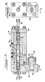
- valve assembly 14 Details of the valve assembly 14 shown schematically in Figures 2 and 3 are set out in Figures 4 and 5.
- Two valve body covers 84 and 86 are secured at opposite ends of the valve body 54.
- a solenoid valve 88 is shown with an electrical conduit 30 for carrying the output signal from the pulse width modulation circuit 28 for application to the solenoid winding 24 of the solenoid valve 88.
- the PWM signal applied to winding 24 determines or regulates the effective fluid flow to chamber 66 and the pressure differential between end chambers 66 and 68 to position the closure member or spool 50 and thereby determine the flow rate through the control line 22.
- the closure member or spool 50 is slidably accomodated within the cylindrical recess or slideway 52 provided in the body portion 54 of the valve assembly such that end chambers 66 and 68 are defined at opposite ends thereof.
- an adjustor 90 Coaxially arranged in each end chamber is an adjustor 90 the axial or linear position of which can be determined by a screw 92 extending through a central internally threaded aperature provided in each end cover.
- the adjustor 90 defines the wall of the end chamber engaged by one end of each compression spring.
- Fluid under pressure is admitted to the control valve assembly through port 32 from whence it flows into end chamber 68. This establishes a certain pressure at this end of the spool.
- the fluid also flows through orifice 40. After passing through orifice 40, the majority of fluid flows to orifice 44.
- the fluid passing through orifice 44 is returned through line 45 to the sump 20.
- After passing through orifice 40 some of the fluid passes to the common point 46 and from thence into end chamber 66.
- the fluid flowing into end chamber 66 establishes a pressure therein which acts against the end of spool 50 in a direction opposed to that pressure applied at the opposite end of the spool.
- the differential pressure established between end chambers 66 and 68 controls the disposition of spool 50 and thereby the fluid flow to the actuator.
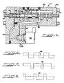
- FIG. 9 An alternative valve spool embodiment is illustrated in Figures 9 and 10.
- the alternative embodiment is similar to that embodiment described above and, therefore, like reference numerals indicate like parts between the illustrations.
- a true three way pilot stage for the valve assembly is provided.
- end chamber 68 remains supplied with a relatively constant flow of fluid such that a relatively constant pressure is established therein.
- the other end chamber 66 is supplied with a fluid flow which establishes an average, controlled pressure therein.
- this average, controlled pressure is established as a function of the duty cycle of solenoid valve 94 which is controlled by a PWM signal employed in the pilot stage of the valve assembly.
- FIG. 10 A schematic representation of the pilot stage of the second embodiment is provided in Figure 10 with details of the entire valve assembly being provided or illustrated in Figure 9.
- fluid under supply pressure may be admitted to the control valve assembly at port 32 from whence the admitted fluid flows into end chamber 68. This establishes a pressure on spool end 76 tending to urge the spool 50 to the left, as seen in Fig. 9.
- Fluid also flows through passageways 96 and 97 to solenoid valve 94 having an electrical winding.
- the operation of the solenoid valve 94 is depicted in a hydraulic format in Figure 10.
- the solenoid valve 94 controls the fluid flow to end chamber 66 over line 99 and to the reservoir 20 over line 45 as a function of the enerization of the solenoid winding 24.
- a normally open orifice 98 which leads to end chamber 66
- a normally closed orifice 100 which leads to the reservoir or sump 20.
- the fluid flow through the orifices 98 and 100 will be proportionately increased or decreased as a function of the duty cycle of the PWM signal.
- the spool end areas 80 and 76 which are exposed to pressure are preferably designed with a 2:1 area ratio, respectively.
Landscapes
- Physics & Mathematics (AREA)
- Fluid Mechanics (AREA)
- General Physics & Mathematics (AREA)
- Engineering & Computer Science (AREA)
- Automation & Control Theory (AREA)
- Magnetically Actuated Valves (AREA)
- Servomotors (AREA)
Applications Claiming Priority (2)
| Application Number | Priority Date | Filing Date | Title |
|---|---|---|---|
| US620887A | 1987-01-23 | 1987-01-23 | |
| US6208 | 1987-01-23 |
Publications (2)
| Publication Number | Publication Date |
|---|---|
| EP0276056A2 true EP0276056A2 (fr) | 1988-07-27 |
| EP0276056A3 EP0276056A3 (fr) | 1989-11-29 |
Family
ID=21719802
Family Applications (1)
| Application Number | Title | Priority Date | Filing Date |
|---|---|---|---|
| EP88300104A Withdrawn EP0276056A3 (fr) | 1987-01-23 | 1988-01-07 | Agencement de vanne pour système de commande de débit de fluide |
Country Status (2)
| Country | Link |
|---|---|
| EP (1) | EP0276056A3 (fr) |
| JP (1) | JPS63186013A (fr) |
Cited By (3)
| Publication number | Priority date | Publication date | Assignee | Title |
|---|---|---|---|---|
| US4883091A (en) * | 1988-12-27 | 1989-11-28 | Ross Operating Valve Company | Multi-port self-regulating proportional pressure control valve |
| EP0460815A3 (en) * | 1990-06-08 | 1992-05-06 | Borg-Warner Automotive, Inc. | Pulse width modulated pressure control valve configuration |
| EP0943811A3 (fr) * | 1998-03-17 | 2002-03-20 | Bürkert Werke GmbH & Co. | Amplificateur fluidique binaire à réglage électrique |
Family Cites Families (2)
| Publication number | Priority date | Publication date | Assignee | Title |
|---|---|---|---|---|
| US4116321A (en) * | 1976-12-27 | 1978-09-26 | Borg-Warner Corporation | Valve arrangement for closed-loop control system |
| DE3225003A1 (de) * | 1982-07-03 | 1984-01-05 | Robert Bosch Gmbh, 7000 Stuttgart | Elektromagnetisch betaetigtes, proportional arbeitendes wegeventil |
-
1988
- 1988-01-07 EP EP88300104A patent/EP0276056A3/fr not_active Withdrawn
- 1988-01-22 JP JP63012455A patent/JPS63186013A/ja active Pending
Cited By (3)
| Publication number | Priority date | Publication date | Assignee | Title |
|---|---|---|---|---|
| US4883091A (en) * | 1988-12-27 | 1989-11-28 | Ross Operating Valve Company | Multi-port self-regulating proportional pressure control valve |
| EP0460815A3 (en) * | 1990-06-08 | 1992-05-06 | Borg-Warner Automotive, Inc. | Pulse width modulated pressure control valve configuration |
| EP0943811A3 (fr) * | 1998-03-17 | 2002-03-20 | Bürkert Werke GmbH & Co. | Amplificateur fluidique binaire à réglage électrique |
Also Published As
| Publication number | Publication date |
|---|---|
| JPS63186013A (ja) | 1988-08-01 |
| EP0276056A3 (fr) | 1989-11-29 |
Similar Documents
| Publication | Publication Date | Title |
|---|---|---|
| US4116321A (en) | Valve arrangement for closed-loop control system | |
| EP0087773B1 (fr) | Système de régulation d'une pompe à déplacement variable et soupape pour ce système | |
| US4572234A (en) | Hydraulic flow control valve | |
| CA1270723A (fr) | Distributeur a tiroir reducteur de pression hydraulique | |
| US4593715A (en) | Hydraulic controllable two-port valve for a liquid stream | |
| US4066006A (en) | Flow regulating system | |
| CA2142659A1 (fr) | Regulateur de pression a commande electronique comportant un solenoide a force variable | |
| EP0015919B1 (fr) | Soupape selectrice a modulation de pression | |
| EP0781381A1 (fr) | Appareil de positionnement et methode d'utilisation de la commande de modulation de largeur d'impulsion d'un cylindre hydraulique a double action | |
| EP0164826B1 (fr) | Régulateur hydraulique proportionel avec solénoide | |
| US3958466A (en) | Electro-hydraulic gear shifting control for vehicle gears | |
| US4437388A (en) | Dual input pressure compensated fluid control valve | |
| US3702621A (en) | Hydraulic servo valve | |
| US4408453A (en) | Hydraulic control system | |
| EP0276056A2 (fr) | Agencement de vanne pour système de commande de débit de fluide | |
| US4566477A (en) | Fluid flow control apparatus | |
| CA2082039A1 (fr) | Systeme de commande hydraulique | |
| US4444297A (en) | Control system for a fluid pressure engaged clutch | |
| JPS57200703A (en) | Liquid pressure apparatus | |
| US4794846A (en) | Proportional action valve with a biased spring unproportionately variable to the load pressure | |
| US4330991A (en) | Load responsive system controls | |
| US6796330B1 (en) | Pressure control apparatus for a torque-transmitting mechanism | |
| US3587617A (en) | Fluid control apparatus | |
| EP0055794B1 (fr) | Transmission hydraulique | |
| US4487304A (en) | Control system for a fluid pressure engaged clutch |
Legal Events
| Date | Code | Title | Description |
|---|---|---|---|
| PUAI | Public reference made under article 153(3) epc to a published international application that has entered the european phase |
Free format text: ORIGINAL CODE: 0009012 |
|
| AK | Designated contracting states |
Kind code of ref document: A2 Designated state(s): DE FR GB IT NL SE |
|
| PUAL | Search report despatched |
Free format text: ORIGINAL CODE: 0009013 |
|
| AK | Designated contracting states |
Kind code of ref document: A3 Designated state(s): DE FR GB IT NL SE |
|
| 17P | Request for examination filed |
Effective date: 19891227 |
|
| STAA | Information on the status of an ep patent application or granted ep patent |
Free format text: STATUS: THE APPLICATION HAS BEEN WITHDRAWN |
|
| 18W | Application withdrawn |
Withdrawal date: 19900502 |
|
| R18W | Application withdrawn (corrected) |
Effective date: 19900502 |