EP0276086A2 - Brûleurs de post-combustion - Google Patents
Brûleurs de post-combustion Download PDFInfo
- Publication number
- EP0276086A2 EP0276086A2 EP88300288A EP88300288A EP0276086A2 EP 0276086 A2 EP0276086 A2 EP 0276086A2 EP 88300288 A EP88300288 A EP 88300288A EP 88300288 A EP88300288 A EP 88300288A EP 0276086 A2 EP0276086 A2 EP 0276086A2
- Authority
- EP
- European Patent Office
- Prior art keywords
- afterburner
- chamber
- exhaust gases
- furnace
- exhaust
- Prior art date
- Legal status (The legal status is an assumption and is not a legal conclusion. Google has not performed a legal analysis and makes no representation as to the accuracy of the status listed.)
- Withdrawn
Links
Images


Classifications
-
- F—MECHANICAL ENGINEERING; LIGHTING; HEATING; WEAPONS; BLASTING
- F23—COMBUSTION APPARATUS; COMBUSTION PROCESSES
- F23G—CREMATION FURNACES; CONSUMING WASTE PRODUCTS BY COMBUSTION
- F23G5/00—Incineration of waste; Incinerator constructions; Details, accessories or control therefor
- F23G5/08—Incineration of waste; Incinerator constructions; Details, accessories or control therefor having supplementary heating
- F23G5/14—Incineration of waste; Incinerator constructions; Details, accessories or control therefor having supplementary heating including secondary combustion
- F23G5/18—Incineration of waste; Incinerator constructions; Details, accessories or control therefor having supplementary heating including secondary combustion in a stack
Definitions
- the present invention relates to afterburners and more particularly to afterburners for burning the exhaust gases from industrial processes or incinerators.
- a number of solutions have been adopted and a known solution is to pass the exhaust gases through a grid of firebricks the exhaust gases tending to heat the firebrick grid and to cause it to glow to an orange heat thereby igniting the exhaust gases which pass through and burning the smoke particles thereby producing a cleaner chimney emission.
- a disadvantage of this system is that although the centre part of the "grid" is well heated the outer edges do not necessarily heat up to a sufficient temperature to burn off the smoke particles and thereby the chimney emission is not clean.
- an afterburner for exhaust gases including means for causing the exhaust gases to move in a spiral manner within a chamber the chamber having an exhaust outlet for a chimney at a selected end thereof said end being predetermined by the desired movement of the exhaust gases.
- the exhaust outlet is situated at an end of the afterburner such that the exhaust gases rotate in an anti-clockwise direction when viewed from the top of the chimney. That is to say the exhaust gases spiral in a clockwise direction up the chimney when viewed from the exhaust outlet of the afterburner.
- the afterburner preferably includes a precombustion chamber within which polluted exhaust gases from a furnace are mixed with air prior to entry into the afterburner chamber.
- the precombustion chamber is preferably generally triangular shaped in cross-section the air inlet being situtated near to a first corner, the exhaust gas inlet near to a second corner and the exhaust into the main afterburner chamber near to the third corner.
- the afterburner is situated on top of a furnace the exhaust gases from the furnace being fed into the precombustion chamber of the afterburner, the afterburner being situated adjacent to the input entry point for scrap material fed into the furnace, the air inlet for the precombustion chamber being situated in a position whereby on opening of the furnace to receive further scrap material the air flow is substantially reduced.
- the reduction is to virtually zero air flow.
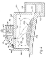
- the afterburner 10 comprises a main combustion chamber 20 and a precombustion chamber 30.
- Exhaust gases E from, for example, a furnace (see Figure 4) enter chamber 30 via openings 32 in the firebrick floor 34 and are mixed with air A from the atmosphere which enters chamber 30 via openings 36 in the firebrick front wall 38.
- the air and exhaust gas mixture (A + E) tends to ignite in the chamber 30 which will be at a very high temperature (once the furnace has been running for some period of time).
- the ignited mixture (A + E) is then constrained to enter the main combustion chamber 20 via openings 22 in the dividing firebrick wall 24.
- the mixture (A + E) enters at the top of chamber 20 and flows as shown by the arrowed path 26 in a general helical manner finally being exhausted through chimney 40 connected to the end wall 28 of chamber 20.
- the chimney 40 is situated at a selected end of chamber 20 such that the exhaust moves up the chimney 40 in a cyclomic manner and rotates in an anticlockwise direction when viewed in plan view as shown in Figure 3. This is important in efficient operation since the cyclonic path imitates the natural movement of, for example, both water draining through a plug hole and is assisted by the natural cyclonic phenomenon.
- the exhaust gases E which normally contain both solid and gaseous contaminants are therefore ignited and precombusted in chamber 30 and then subjected to a further combustion process in chamber 20 in which the cyclonic movement causes any particles to strike the walls of chamber 20 which become extremely hot (normally to white heat) thereby completely burning such particles.
- the gas mixture (A + E) entering chamber 20 is already preheated, firstly in the furnace and then in chamber 30 and therefore chamber 20 is at an extreme temperature causing combustion of virtually all contaminant material whether gaseous or solid.
- an inlet 42 is preferably provided for introduction of an air/fuel mixture into chamber 20 at an end opposite to chimney 40. This is to assist in the start up of the afterburner and the air/fuel mixture may be modified to an air supply only once the afterburner has reached full operating temperature. Alternatively it may be shut off completely.
- a furnace 100 is indicated by wall member 102 and indicates that afterburner 10 may be placed at any convenient position to receive contaminated exhaust gases.
- the furnace 100 is of the sloping hearth type wherein contaminated scrap material 200 is fed onto the hearth 104 through a door 106.
- Door 106 is opened by sliding vertically in the direction indicated by arrow 108.
- Furnace 100 is provided with an outlet 110 for example for molten aluminium 112 which is collected in a bath 114 at the end of the furnace remote from the door 106.
- the aluminium may be tapped from bath 114 in known manner.
- Furnace 100 may be provided with a "start up" burner 116 in known manner to commence the combustion within a main chamber 120. Once combustion has commenced burner 116 may be shut off or continued to operate at a predetermined level dependent on the type of scrap introduced.
- exhaust gases E normally heavily contaminated pass through the opening 32 which in firebrick wall 34 is now an integral part of the roof of furnace 100.
- afterburner 10 may be placed on top of a complete roof 102 of furnace 100 and corresponding matching holes provided to allow exhaust gases E to enter chamber 30.
- the afterburner operates as described hereinbefore until further scrap material is introduced into chamber 120. Lifting of door 106 effectively blocks off inlet holes 36 and thereby reduces the chimney draught. Thus, new scrap material is allowed to burn initially more slowly until door 106 is again closed and thereby the excess contaminant which is present on new scrap will not be drawn up the chimney 40 at so high a rate that it cannot be burnt. The gases given off will be contained within chamber 120 and when door 106 closes they will then be gradually drawn off to be consumed in afterburner 10.
Landscapes
- Engineering & Computer Science (AREA)
- Mechanical Engineering (AREA)
- General Engineering & Computer Science (AREA)
- Incineration Of Waste (AREA)
Applications Claiming Priority (2)
| Application Number | Priority Date | Filing Date | Title |
|---|---|---|---|
| GB8701000A GB2199929B (en) | 1987-01-17 | 1987-01-17 | Afterburners |
| GB8701000 | 1987-01-17 |
Publications (2)
| Publication Number | Publication Date |
|---|---|
| EP0276086A2 true EP0276086A2 (fr) | 1988-07-27 |
| EP0276086A3 EP0276086A3 (fr) | 1989-04-12 |
Family
ID=10610822
Family Applications (1)
| Application Number | Title | Priority Date | Filing Date |
|---|---|---|---|
| EP88300288A Withdrawn EP0276086A3 (fr) | 1987-01-17 | 1988-01-14 | Brûleurs de post-combustion |
Country Status (2)
| Country | Link |
|---|---|
| EP (1) | EP0276086A3 (fr) |
| GB (1) | GB2199929B (fr) |
Cited By (2)
| Publication number | Priority date | Publication date | Assignee | Title |
|---|---|---|---|---|
| KR100659299B1 (ko) * | 2005-11-21 | 2006-12-19 | 권혁대 | 특수 폐기물 소각로 |
| GB2495274A (en) * | 2011-09-27 | 2013-04-10 | Anthony Noel Redman | Combustion hot gases with helical flow |
Families Citing this family (3)
| Publication number | Priority date | Publication date | Assignee | Title |
|---|---|---|---|---|
| GB2253687A (en) * | 1991-03-12 | 1992-09-16 | Richard Ernest Sherratt | An incinerator |
| GB9121648D0 (en) * | 1991-10-11 | 1991-11-27 | D & C Eng Bv | A combustor apparatus |
| DE102011116723A1 (de) * | 2011-10-24 | 2013-04-25 | Robert Bosch Gmbh | Sekundärbrennkammer mit Sekundärlufteindüsung |
Family Cites Families (16)
| Publication number | Priority date | Publication date | Assignee | Title |
|---|---|---|---|---|
| GB1054610A (fr) * | ||||
| GB1004785A (en) * | 1962-08-17 | 1965-09-15 | Prat Daniels Stroud Ltd | Improvements in or relating to smoke-consuming apparatus |
| US3567399A (en) * | 1968-06-03 | 1971-03-02 | Kaiser Aluminium Chem Corp | Waste combustion afterburner |
| US3610179A (en) * | 1970-02-27 | 1971-10-05 | Alexander Shaw Jr | Incinerator |
| US3960504A (en) * | 1973-09-17 | 1976-06-01 | Griffin Research & Development, Inc. | Polluted air effluent incinerating apparatus |
| US4106892A (en) * | 1975-12-04 | 1978-08-15 | Kureha Kagaku Kogyo Kabushiki Kaisha | Apparatus for heat treatment using downwardly swirling hot gas flow |
| AU501445B2 (en) * | 1976-04-09 | 1979-06-21 | Continental Carbon Company | Combustion of waste gases |
| JPS5380836A (en) * | 1976-12-27 | 1978-07-17 | Hokkaido Sugar Co | Method of dustless combustion and combustion furnace therefor |
| GB2001419A (en) * | 1977-07-18 | 1979-01-31 | Zink Co John | Apparatus for burning waste particulate matter |
| US4124681A (en) * | 1977-08-15 | 1978-11-07 | John Zink Company | Particulate carbon disposal by combustion |
| DE2745488C2 (de) * | 1977-10-10 | 1986-04-30 | Bayer Ag, 5090 Leverkusen | Verfahren und Vorrichtung zur Verbrennung explosibler Gase |
| DE2745493A1 (de) * | 1977-10-10 | 1979-04-19 | Bayer Ag | Verfahren und vorrichtung zur verbrennung explosibler gase |
| DE2826210A1 (de) * | 1978-06-15 | 1979-12-20 | Kernforschungsanlage Juelich | Vorrichtung zum verbrennen von in einem gasgemisch als schwebeteilchen mitgefuehrten stoffen |
| JPS56916A (en) * | 1979-06-15 | 1981-01-08 | Hokkaido Togyo Kk | Method and apparatus for generating hot blast for incineration of chaff |
| GB2060844A (en) * | 1979-10-17 | 1981-05-07 | Weber K | Incinerator apparatus |
| US4280417A (en) * | 1979-11-28 | 1981-07-28 | Bruun & Sorensen Ab | Incineration plant |
-
1987
- 1987-01-17 GB GB8701000A patent/GB2199929B/en not_active Expired - Fee Related
-
1988
- 1988-01-14 EP EP88300288A patent/EP0276086A3/fr not_active Withdrawn
Cited By (2)
| Publication number | Priority date | Publication date | Assignee | Title |
|---|---|---|---|---|
| KR100659299B1 (ko) * | 2005-11-21 | 2006-12-19 | 권혁대 | 특수 폐기물 소각로 |
| GB2495274A (en) * | 2011-09-27 | 2013-04-10 | Anthony Noel Redman | Combustion hot gases with helical flow |
Also Published As
| Publication number | Publication date |
|---|---|
| EP0276086A3 (fr) | 1989-04-12 |
| GB2199929B (en) | 1990-12-05 |
| GB2199929A (en) | 1988-07-20 |
| GB8701000D0 (en) | 1987-02-18 |
Similar Documents
| Publication | Publication Date | Title |
|---|---|---|
| US3310009A (en) | Incinerator for refuse material | |
| WO2005100861A1 (fr) | Appareil de combustion pour combustible solide | |
| US4280417A (en) | Incineration plant | |
| US6324999B1 (en) | Incinerator for removing noxious substances | |
| CN2581822Y (zh) | 一种垃圾热解焚烧炉 | |
| US4402738A (en) | Method and apparatus for incinerating self-burning wastes | |
| GB2199929A (en) | Afterburners | |
| US6213116B1 (en) | Wood and multi-fuel burning stove | |
| JP3430295B2 (ja) | ごみ焼却時に生成するダイオキシンとフランを減らすための方法及びその設備 | |
| JPH06341625A (ja) | ゴミ焼却炉 | |
| EP0805305A2 (fr) | Fours crématoires | |
| JP2005326076A (ja) | 廃棄物焼却炉 | |
| US3538864A (en) | Calcination cremator | |
| RU2117871C1 (ru) | Инсинератор | |
| JPH0942634A (ja) | 廃棄物の焼却炉 | |
| JP2678254B2 (ja) | ゴミ焼却炉 | |
| RU211085U1 (ru) | Устройство для термической переработки отходов | |
| CN2460868Y (zh) | 尾部二次燃烧设备 | |
| US3832144A (en) | Smoke eliminator | |
| CN2400695Y (zh) | 一种处理氮氧化物废气的焚烧炉 | |
| US5317978A (en) | Incinerating furnace | |
| JP2539568B2 (ja) | 焼却炉 | |
| JP3001326U (ja) | 焼却炉 | |
| JP3006658U (ja) | 焼却炉 | |
| CN2135721Y (zh) | 工业窑炉消除黑烟的二次燃烧装置 |
Legal Events
| Date | Code | Title | Description |
|---|---|---|---|
| PUAI | Public reference made under article 153(3) epc to a published international application that has entered the european phase |
Free format text: ORIGINAL CODE: 0009012 |
|
| AK | Designated contracting states |
Kind code of ref document: A2 Designated state(s): AT BE CH DE ES FR GB GR IT LI LU NL SE |
|
| PUAL | Search report despatched |
Free format text: ORIGINAL CODE: 0009013 |
|
| AK | Designated contracting states |
Kind code of ref document: A3 Designated state(s): AT BE CH DE ES FR GB GR IT LI LU NL SE |
|
| STAA | Information on the status of an ep patent application or granted ep patent |
Free format text: STATUS: THE APPLICATION IS DEEMED TO BE WITHDRAWN |
|
| 18D | Application deemed to be withdrawn |
Effective date: 19891013 |