EP0276123A2 - Dispositif de génération de champ magnétique - Google Patents
Dispositif de génération de champ magnétique Download PDFInfo
- Publication number
- EP0276123A2 EP0276123A2 EP88300413A EP88300413A EP0276123A2 EP 0276123 A2 EP0276123 A2 EP 0276123A2 EP 88300413 A EP88300413 A EP 88300413A EP 88300413 A EP88300413 A EP 88300413A EP 0276123 A2 EP0276123 A2 EP 0276123A2
- Authority
- EP
- European Patent Office
- Prior art keywords
- magnetic field
- shield
- field generating
- generating means
- coils
- Prior art date
- Legal status (The legal status is an assumption and is not a legal conclusion. Google has not performed a legal analysis and makes no representation as to the accuracy of the status listed.)
- Granted
Links
Images




Classifications
-
- H—ELECTRICITY
- H05—ELECTRIC TECHNIQUES NOT OTHERWISE PROVIDED FOR
- H05H—PLASMA TECHNIQUE; PRODUCTION OF ACCELERATED ELECTRICALLY-CHARGED PARTICLES OR OF NEUTRONS; PRODUCTION OR ACCELERATION OF NEUTRAL MOLECULAR OR ATOMIC BEAMS
- H05H7/00—Details of devices of the types covered by groups H05H9/00, H05H11/00, H05H13/00
- H05H7/04—Magnet systems, e.g. undulators, wigglers; Energisation thereof
-
- H—ELECTRICITY
- H01—ELECTRIC ELEMENTS
- H01F—MAGNETS; INDUCTANCES; TRANSFORMERS; SELECTION OF MATERIALS FOR THEIR MAGNETIC PROPERTIES
- H01F6/00—Superconducting magnets; Superconducting coils
-
- H—ELECTRICITY
- H05—ELECTRIC TECHNIQUES NOT OTHERWISE PROVIDED FOR
- H05H—PLASMA TECHNIQUE; PRODUCTION OF ACCELERATED ELECTRICALLY-CHARGED PARTICLES OR OF NEUTRONS; PRODUCTION OR ACCELERATION OF NEUTRAL MOLECULAR OR ATOMIC BEAMS
- H05H13/00—Magnetic resonance accelerators; Cyclotrons
Definitions
- the invention relates to magnetic field generating assemblies and in particular those assemblies used in cyclotrons, magnetic resonance imagers and other applications where large magnetic fields are generated.
- This cyclotron includes a magnetic field generator formed from superconducting coils housed in a cryostat.
- the field generated in the cyclotron has a mean value of 2.5T and a peak field considerably in excess of this.
- relatively large bore fields are also generated.
- the generation of large internal fields is accompanied by the generation of relatively large external or fringe fields outside the main apparatus and extending through a relatively large radius.
- these fringe fields have been shielded by siting the apparatus within a large external iron shield.
- iron has a non-linear saturation property.
- a given iron shield acts as a good "conduit" for magnetic flux (ie. there is no flux leakage from the shield)
- the iron fails to contain all the flux. This is because the iron starts to saturate.
- the only solution to this problem is to increase the amount of iron used.
- a magnetic field generating assembly comprising first magnetic field generating means for generating a first magnetic field; a ferro-magnetic shield positioned about the first magnetic field generating means; and second magnetic field generating means for guiding magnetic flux of the first magnetic field leaking out of the shield back into into the shield.
- the first magnetic field generating means is tubular, and, in most cases, the first magnetic field generating means will have a circular cross-section and be cylindrical.
- the first magnetic field generating means may be provided by one or more cylindrical, electrical coils.
- the shield which is conveniently made of iron, is preferably tubular with the first magnetic field generating means being positioned within the shield.
- the shield is preferably continuous but could be segmented in the radial plane and the axial plane.
- the shield has inwardly projecting flanges at each end. These flanges assist in maximising the flux which is guided into the shield.
- the second magnetic field generating means may, like the first magnetic field generating means, be provided by one or more permanent magnets but is conveniently defined by at least one electrical coil. This latter arrangement has the advantage that the strength of the magnetic field generated by this coil can be varied to obtain optimum conditions.
- the second magnetic field generating means may be positioned at least partly outwardly of the shield and/or at each end of the shield.
- the second magnetic field generating means comprises one or more electrical coils mounted closely to the shield.
- the or each coil is in the form of a thin current sheet and provides a "flux wall" to contain the flux within the shield.
- first and second magnetic field generating means may be provided by resistive electrical coils but typically the first magnetic field generating means comprises a superconducting magnet defined by one or more coils positioned within a cryostat.
- the shield could be positioned outside the cryostat, it is preferably provided within the cryostat, most preferably in the same temperature region as the coils of the first magnetic field generating means. This latter arrangement reduces the overall bulk of the assembly.
- the second magnetic field generating means may also comprise at least one superconducting coil positioned within the cryostat, preferably within the same temperature region as the first magnetic field generating means.
- first and second magnetic field generating means comprise electrical coils
- these coils are preferably connected in series so that changes in currents applied to the first magnetic field generating means are duplicated in the second magnetic field generating means automatically and so compensating fields are automatically produced at the correct strength.
- One important application of the invention is in the field of cyclotrons.
- the cyclotron shown in cross-section in Figure 1 has a construction very similar to that illustrated in our International Patent Application No.PCT/GB86/00284.
- the cyclotron has three dees defined by respective, axially aligned pairs of sector-shaped members substantially equally circumferentially spaced around an axis 1 of the cyclotron and positioned within an evacuated chamber. Two pairs of the sector-shaped members 2, 3; 4, 5 are shown in Figure 1. These dees provide radio frequency energisation to a beam of charged particles orbiting in a beam space 6 defined at the centre of the cyclotron between respective pairs of the sector-shaped members. Interleaved between each pair of dees are provided opposed pole pieces two of which 7, 8 are shown in Figure 1. The pole pieces are designed and selected so as to provide the required variations in magnetic field strength in an axial magnetic field generated within the cyclotron by means to be described below.
- Radiofrequency energisation is fed via three coaxial cables one of which is indicated at 9 into the cavities defined by the dees so as to produce a large oscillating voltage between the axially opposed ends of each dee cavity adjacent the beam space 6.
- An ion source is provided at 10 which generates a stream of negatively charged ions which are guided along the axis 1 of the cyclotron between the dees and into the beam space 6.
- the existence of the axial magnetic field causes the ions to move in a curved path within the beam space 6 so that they continually cross the gaps defined between adjacent dees. Since three dees are provided, six gaps are defined. As the ions cross each gap, they are accelerated by the radiofrequency field and consequently increase in energy. This increase in energy causes the radius of the ion path to increase so that the ions describe a spiral path.
- a beam outlet aperture 11 is provided in the beam space 6 aligned with a delivery pipe 12 passing out of the cyclotron. Positioned across the outlet 11 is a holder 13 slidably mounted in a slideway 14. The holder 13 has a number of radially inwardly facing legs 15 between each pair of which is mounted a thin carbon foil 16.
- each carbon foil 16 has a limited life, it can easily be replaced without the necessity of gaining access to the interior of the cyclotron by simply sliding the holder 13 along the slideway 14 to bring the next foil 16 into the outlet aperture 11.
- the movement and position of the holder 13 can be controlled externally of the cyclotron by means not shown.
- the region through which the beam passes is evacuated in a conventional manner via an evacuating module shown diagrammatically at 17.
- the axial magnetic field is generated by a pair of main, superconducting coils 18, 19.
- Each coil 18, 19 is mounted coaxially with the axis 1 of the cyclotron on a former 20. Typically, these coils will produce a magnetic field within the cyclotron of about 3T.
- each of the main coils 18, 19 have + 681kAmp-turns and a current density of 130Amp/mm2.
- the main coils 18, 19 need to be superconducting in order to generate the large field required, and in order to achieve superconduction, it is necessary to reduce the temperature of the coils to that of liquid helium. This is achieved by placing the coils 18, 19 within a cryostat 21.
- the cryostat 21 comprises an inner helium vessel 22, the radially inner wall of which is defined by the former 20. Helium is supplied through an inlet port 23 in a conventional manner.
- the helium vessel 22 is supported by an outer wall 24 of the cyclotron via radially extending supports 25 made from low heat conduction material such as glass fibre. Two of the supports 25 are shown in Figure 1.
- the helium vessel 22 is suspended within a gas cooled shield 26 with the space between the shield and the vessel defining a vacuum.
- the shield 26 is cooled by boiling helium via the connection 27.
- the gas cooled shield 26 Around the gas cooled shield 26 is mounted another shield 28 cooled by liquid nitrogen contained within reservoirs 29, 30. These reservoirs are supplied with liquid nitrogen via inlet ports 31, 32.
- the nitrogen cooled shield 28 is mounted within a vacuum defined by the outer wall 24 of the cryostat and an inner wall 33.
- a mild steel shield 34 having a generally cylindrical form is mounted within the helium vessel 22 around the main coils 18, 19.
- the shield 34 has a cylindrical section 35 connected with radially inwardly extending flanges 36, 37.
- the shield 34 is mounted to the former 20 via two mild steel annuli 38, 39 welded to the former 20. This can be seen in more detail in Figure 2.
- the cylindrical portion 35 of the shield 34 is connected with the flanges 36, 37 via a pair of annular spacers of mild steel 40, 41 and a set of circumferentially spaced bolts 42 two of which are shown in Figure 1.
- the main coils 18, 19 are secured axially by the mild steel annuli 38, 39 and a central stainless steel spacer 43.
- An aluminium former 44 of cylindrical form is mounted on the radially outer surface of the shield 34.
- the former 44 is constrained against axial movement by a pair of flanges 45, 46 integrally formed with the spacers 40, 41.
- the former 44 defines a pair of axially spaced grooves 47, 48 aligned with the main coils 18, 19 and within which are positioned a pair of thin auxiliary coils 49, 50.
- the auxiliary coils 49, 50 are electrically connected in series with the main coils 18, 19 and define a similar current density of 130Amps/mm2. These coils 49, 50 are wound so as to generate a secondary magnetic field which increases the flux in the shield 34.
- auxiliary coils 51, 52 are mounted at opposite axial ends of the shield 34.
- auxiliary coils 51, 52 each comprise an inner coil 51A, 52A and an outer coil 51B, 52B each coaxial with the axis 1 of the cyclotron.
- the coils 51, 52 are secured in position by annular stainless steel members 53, 54 and bolts 55.
- the disc shaped coils 51, 52 again define a current density of 130Amps/mm2, and generate a magnetic field to increase the flux in the shield 34.
- the coils 49, 50 have - 177kAmp-turns each, and the coils 51, 52 each have about - 143kAmp-turns.
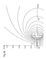
- Figure 3A illustrates the lines of magnetic flux due to the main coils 18, 19 when both the shield 34 and auxiliary coils 49-52 have been omitted.
- Figure 3A also illustrates two of the pole pieces 56, 57 which are circumferentially spaced from the pole pieces 7, 8. As can be seen in Figure 3A, the lines of magnetic flux extend outwardly to distances of 2 metres and beyond.
- Figure 3B illustrates the same situation as Figure 3A but in terms of lines of constant magnetic field.
- a magnetic field of 5mT is indicated by a line 58 while a field of 50mT is indicated by a line 59. It will be seen that the field has a magnitude of 50mT at about 1 metre from the axis 1 of the cyclotron and still has a significantly large magnetic field of 5mT at 2 metres from the axis.
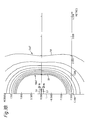
- Figure 4A illustrates the effect on the magnetic flux lines of positioning the shield 34 around the main coils 18, 19.
- the shield is close to saturation and so there is a significant leakage of flux lines, for example flux line 60, from the shield 34.
- This leakage has the effect of producing a significant magnetic field of 5mT at about 1.5m from the axis 1 of the cyclotron as can be seen by the line 58 in Figure 4B.
- the line 59 in Figure 4B illustrates a field of 50mT. This degree of shielding is not satisfactory for most purposes.
- the auxiliary coils 49-52 are provided.
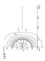
- the effect of these coils in combination with the shield 34 is illustrated in Figure 5A which shows that the auxiliary coils push or guide the leaking flux lines back into the shield 34.
- the effect of this on the external magnetic field can be seen in Figure 5B where the 5mT line 58 is positioned between 0.5 and 1 metre from the axis 1 while the 0.5mT line 61 is positioned at about 1 metre from the axis. It will be seen therefore that this combination of shield 34 and auxiliary coils 49, 52 reduces very significantly the fringe magnetic field due to the main coils 18, 19.
Landscapes
- Physics & Mathematics (AREA)
- Engineering & Computer Science (AREA)
- Plasma & Fusion (AREA)
- Spectroscopy & Molecular Physics (AREA)
- Power Engineering (AREA)
- Optics & Photonics (AREA)
- Particle Accelerators (AREA)
- Magnetic Resonance Imaging Apparatus (AREA)
Applications Claiming Priority (2)
| Application Number | Priority Date | Filing Date | Title |
|---|---|---|---|
| GB8701363 | 1987-01-22 | ||
| GB878701363A GB8701363D0 (en) | 1987-01-22 | 1987-01-22 | Magnetic field generating assembly |
Publications (3)
| Publication Number | Publication Date |
|---|---|
| EP0276123A2 true EP0276123A2 (fr) | 1988-07-27 |
| EP0276123A3 EP0276123A3 (en) | 1989-07-26 |
| EP0276123B1 EP0276123B1 (fr) | 1994-06-29 |
Family
ID=10611037
Family Applications (1)
| Application Number | Title | Priority Date | Filing Date |
|---|---|---|---|
| EP88300413A Expired - Lifetime EP0276123B1 (fr) | 1987-01-22 | 1988-01-19 | Dispositif de génération de champ magnétique |
Country Status (5)
| Country | Link |
|---|---|
| US (1) | US4968915A (fr) |
| EP (1) | EP0276123B1 (fr) |
| JP (1) | JP2572250B2 (fr) |
| DE (1) | DE3850416T2 (fr) |
| GB (1) | GB8701363D0 (fr) |
Cited By (12)
| Publication number | Priority date | Publication date | Assignee | Title |
|---|---|---|---|---|
| GB2232771A (en) * | 1989-04-23 | 1990-12-19 | Elscint Ltd | Actively and passively shielded MR magnet |
| EP0936290A1 (fr) * | 1998-02-17 | 1999-08-18 | Kabushiki Kaisha Toshiba | Dispositif d'électro-aimant à supraconductivité pour un appareil de tirage de cristaux |
| EP0940687A3 (fr) * | 1998-03-05 | 2001-03-21 | General Electric Company | Structure ouverte d' aimant blindé |
| EP0964263A3 (fr) * | 1998-02-19 | 2001-03-21 | General Electric Company | Aimant supraconducteur ouvert et blindé |
| EP2814304A1 (fr) * | 2013-06-12 | 2014-12-17 | Mevion Medical Systems, Inc. | Accélérateur de particules qui produit des particules chargées ayant des énergies variables |
| US9622335B2 (en) | 2012-09-28 | 2017-04-11 | Mevion Medical Systems, Inc. | Magnetic field regenerator |
| US9681531B2 (en) | 2012-09-28 | 2017-06-13 | Mevion Medical Systems, Inc. | Control system for a particle accelerator |
| US9706636B2 (en) | 2012-09-28 | 2017-07-11 | Mevion Medical Systems, Inc. | Adjusting energy of a particle beam |
| US9723705B2 (en) | 2012-09-28 | 2017-08-01 | Mevion Medical Systems, Inc. | Controlling intensity of a particle beam |
| US10155124B2 (en) | 2012-09-28 | 2018-12-18 | Mevion Medical Systems, Inc. | Controlling particle therapy |
| US10254739B2 (en) | 2012-09-28 | 2019-04-09 | Mevion Medical Systems, Inc. | Coil positioning system |
| USRE48047E1 (en) | 2004-07-21 | 2020-06-09 | Mevion Medical Systems, Inc. | Programmable radio frequency waveform generator for a synchrocyclotron |
Families Citing this family (29)
| Publication number | Priority date | Publication date | Assignee | Title |
|---|---|---|---|---|
| US5359310A (en) * | 1992-04-15 | 1994-10-25 | Houston Advanced Research Center | Ultrashort cylindrical shielded electromagnet for magnetic resonance imaging |
| US5382904A (en) * | 1992-04-15 | 1995-01-17 | Houston Advanced Research Center | Structured coil electromagnets for magnetic resonance imaging and method for fabricating the same |
| US5290638A (en) * | 1992-07-24 | 1994-03-01 | Massachusetts Institute Of Technology | Superconducting joint with niobium-tin |
| US6208143B1 (en) * | 1998-04-10 | 2001-03-27 | The Board Of Trustee Of The Leland Stanford Junior University | Biplanar homogeneous field electromagnets and method for making same |
| ES2730108T3 (es) | 2005-11-18 | 2019-11-08 | Mevion Medical Systems Inc | Radioterapia de partículas cargadas |
| WO2007117335A2 (fr) * | 2006-01-04 | 2007-10-18 | University Of Utah Research Foundation | Systeme de generation de champ magnetique a haute intensite et procedes associes |
| JP5481070B2 (ja) * | 2006-01-19 | 2014-04-23 | マサチューセッツ インスティテュート オブ テクノロジー | 粒子加速のための磁場生成方法、磁石構造体及びその製造方法 |
| US7656258B1 (en) | 2006-01-19 | 2010-02-02 | Massachusetts Institute Of Technology | Magnet structure for particle acceleration |
| US8933650B2 (en) | 2007-11-30 | 2015-01-13 | Mevion Medical Systems, Inc. | Matching a resonant frequency of a resonant cavity to a frequency of an input voltage |
| US8581523B2 (en) | 2007-11-30 | 2013-11-12 | Mevion Medical Systems, Inc. | Interrupted particle source |
| US8106570B2 (en) * | 2009-05-05 | 2012-01-31 | General Electric Company | Isotope production system and cyclotron having reduced magnetic stray fields |
| US8525447B2 (en) | 2010-11-22 | 2013-09-03 | Massachusetts Institute Of Technology | Compact cold, weak-focusing, superconducting cyclotron |
| US8975836B2 (en) * | 2012-07-27 | 2015-03-10 | Massachusetts Institute Of Technology | Ultra-light, magnetically shielded, high-current, compact cyclotron |
| CN104813747B (zh) | 2012-09-28 | 2018-02-02 | 梅维昂医疗系统股份有限公司 | 使用磁场颤振聚焦粒子束 |
| TW201422279A (zh) | 2012-09-28 | 2014-06-16 | Mevion Medical Systems Inc | 聚焦粒子束 |
| EP2901824B1 (fr) | 2012-09-28 | 2020-04-15 | Mevion Medical Systems, Inc. | Éléments d'homogénéisation de champ magnétique permettant d'ajuster la position de la bobine principale et procédé correspondant |
| US8791656B1 (en) * | 2013-05-31 | 2014-07-29 | Mevion Medical Systems, Inc. | Active return system |
| EP3049151B1 (fr) | 2013-09-27 | 2019-12-25 | Mevion Medical Systems, Inc. | Balayage par un faisceau de particules |
| US9962560B2 (en) | 2013-12-20 | 2018-05-08 | Mevion Medical Systems, Inc. | Collimator and energy degrader |
| US10675487B2 (en) | 2013-12-20 | 2020-06-09 | Mevion Medical Systems, Inc. | Energy degrader enabling high-speed energy switching |
| US9661736B2 (en) | 2014-02-20 | 2017-05-23 | Mevion Medical Systems, Inc. | Scanning system for a particle therapy system |
| US9950194B2 (en) | 2014-09-09 | 2018-04-24 | Mevion Medical Systems, Inc. | Patient positioning system |
| JP6231039B2 (ja) * | 2015-04-22 | 2017-11-15 | 住友重機械工業株式会社 | サイクロトロン及び超伝導電磁石 |
| US10786689B2 (en) | 2015-11-10 | 2020-09-29 | Mevion Medical Systems, Inc. | Adaptive aperture |
| US10925147B2 (en) | 2016-07-08 | 2021-02-16 | Mevion Medical Systems, Inc. | Treatment planning |
| US11103730B2 (en) | 2017-02-23 | 2021-08-31 | Mevion Medical Systems, Inc. | Automated treatment in particle therapy |
| JP6940676B2 (ja) | 2017-06-30 | 2021-09-29 | メビオン・メディカル・システムズ・インコーポレーテッド | リニアモーターを使用して制御される構成可能コリメータ |
| EP3934751B1 (fr) | 2019-03-08 | 2024-07-17 | Mevion Medical Systems, Inc. | Collimateur et dégradeur d'énergie pour système de thérapie par particules |
| CN118362949B (zh) * | 2024-06-19 | 2024-10-01 | 四川省地球物理调查研究所 | 一种磁场强度检测仪 |
Family Cites Families (7)
| Publication number | Priority date | Publication date | Assignee | Title |
|---|---|---|---|---|
| CA966893A (en) * | 1973-06-19 | 1975-04-29 | Her Majesty In Right Of Canada As Represented By Atomic Energy Of Canada Limited | Superconducting cyclotron |
| FR2551302B1 (fr) * | 1983-08-30 | 1986-03-14 | Commissariat Energie Atomique | Structure ferromagnetique d'une source d'ions creee par des aimants permanents et des solenoides |
| NL8303535A (nl) * | 1983-10-14 | 1985-05-01 | Philips Nv | Kernspinresonantie apparaat. |
| US4587504A (en) * | 1983-11-11 | 1986-05-06 | Oxford Magnet Technology Limited | Magnet assembly for use in NMR apparatus |
| US4641104A (en) * | 1984-04-26 | 1987-02-03 | Board Of Trustees Operating Michigan State University | Superconducting medical cyclotron |
| DE3505281A1 (de) * | 1985-02-15 | 1986-08-21 | Siemens AG, 1000 Berlin und 8000 München | Magnetfelderzeugende einrichtung |
| GB8512804D0 (en) * | 1985-05-21 | 1985-06-26 | Oxford Instr Ltd | Cyclotrons |
-
1987
- 1987-01-22 GB GB878701363A patent/GB8701363D0/en active Pending
-
1988
- 1988-01-19 EP EP88300413A patent/EP0276123B1/fr not_active Expired - Lifetime
- 1988-01-19 DE DE3850416T patent/DE3850416T2/de not_active Expired - Fee Related
- 1988-01-22 JP JP63012447A patent/JP2572250B2/ja not_active Expired - Fee Related
-
1989
- 1989-06-15 US US07/366,355 patent/US4968915A/en not_active Expired - Lifetime
Cited By (17)
| Publication number | Priority date | Publication date | Assignee | Title |
|---|---|---|---|---|
| GB2232771A (en) * | 1989-04-23 | 1990-12-19 | Elscint Ltd | Actively and passively shielded MR magnet |
| GB2232771B (en) * | 1989-04-23 | 1994-01-05 | Elscint Ltd | Integrated active shielded magnet system |
| EP0936290A1 (fr) * | 1998-02-17 | 1999-08-18 | Kabushiki Kaisha Toshiba | Dispositif d'électro-aimant à supraconductivité pour un appareil de tirage de cristaux |
| US6060971A (en) * | 1998-02-17 | 2000-05-09 | Kabushiki Kaisha Toshiba | Superconducting magnet device for crystal pulling device |
| CN1320172C (zh) * | 1998-02-17 | 2007-06-06 | 东芝株式会社 | 拉晶装置用的超导磁体装置 |
| EP0964263A3 (fr) * | 1998-02-19 | 2001-03-21 | General Electric Company | Aimant supraconducteur ouvert et blindé |
| EP0940687A3 (fr) * | 1998-03-05 | 2001-03-21 | General Electric Company | Structure ouverte d' aimant blindé |
| USRE48047E1 (en) | 2004-07-21 | 2020-06-09 | Mevion Medical Systems, Inc. | Programmable radio frequency waveform generator for a synchrocyclotron |
| US9622335B2 (en) | 2012-09-28 | 2017-04-11 | Mevion Medical Systems, Inc. | Magnetic field regenerator |
| US9681531B2 (en) | 2012-09-28 | 2017-06-13 | Mevion Medical Systems, Inc. | Control system for a particle accelerator |
| US9706636B2 (en) | 2012-09-28 | 2017-07-11 | Mevion Medical Systems, Inc. | Adjusting energy of a particle beam |
| US9723705B2 (en) | 2012-09-28 | 2017-08-01 | Mevion Medical Systems, Inc. | Controlling intensity of a particle beam |
| US10155124B2 (en) | 2012-09-28 | 2018-12-18 | Mevion Medical Systems, Inc. | Controlling particle therapy |
| US10254739B2 (en) | 2012-09-28 | 2019-04-09 | Mevion Medical Systems, Inc. | Coil positioning system |
| US10368429B2 (en) | 2012-09-28 | 2019-07-30 | Mevion Medical Systems, Inc. | Magnetic field regenerator |
| US9730308B2 (en) | 2013-06-12 | 2017-08-08 | Mevion Medical Systems, Inc. | Particle accelerator that produces charged particles having variable energies |
| EP2814304A1 (fr) * | 2013-06-12 | 2014-12-17 | Mevion Medical Systems, Inc. | Accélérateur de particules qui produit des particules chargées ayant des énergies variables |
Also Published As
| Publication number | Publication date |
|---|---|
| EP0276123B1 (fr) | 1994-06-29 |
| DE3850416T2 (de) | 1995-01-26 |
| JP2572250B2 (ja) | 1997-01-16 |
| JPS63199406A (ja) | 1988-08-17 |
| US4968915A (en) | 1990-11-06 |
| GB8701363D0 (en) | 1987-02-25 |
| DE3850416D1 (de) | 1994-08-04 |
| EP0276123A3 (en) | 1989-07-26 |
Similar Documents
| Publication | Publication Date | Title |
|---|---|---|
| EP0276123B1 (fr) | Dispositif de génération de champ magnétique | |
| US6057655A (en) | Method for sweeping charged particles out of an isochronous cyclotron, and device therefor | |
| US4943781A (en) | Cyclotron with yokeless superconducting magnet | |
| US4734653A (en) | Magnetic field apparatus for a particle accelerator having a supplemental winding with a hollow groove structure | |
| US9805901B2 (en) | Compact magnet design for high-power magnetrons | |
| WO2017160758A1 (fr) | Accélération de particules dans un synchrocyclotron à énergie variable par circuit d'excitation rf à fréquence variable accordé unique | |
| US9711314B2 (en) | Compact magnet system for a high-power millimeter-wave gyrotron | |
| Zavodszky et al. | Status report on the design and construction of the Superconducting Source for Ions at the National Superconducting Cyclotron Laboratory/Michigan State University | |
| Cavenago et al. | Optimization studies of a 14.4 GHz ECR ion source for the superconductive linac at Legnaro | |
| WO2018096648A1 (fr) | Accélérateur et dispositif de projection de faisceau de particules | |
| Anashin et al. | Compact storage rings Siberia‐AS and Siberia‐SM synchrotron radiation sources for lithography | |
| Xie | Performance of the upgraded LBNL AECR ion source | |
| Willax | Proposal for a 500 MeV Isochronous Cyolotron with Ring Magnet | |
| Lyneis | Design of the 3rd generation ECR ion source | |
| Schryber et al. | Status report on the new injector at SIN | |
| Taccetti et al. | A CHI wiggler ubitron amplifier experiment: Wiggler characterization | |
| Michaelis | Status of the Cern Synchrocyclotron Improvement Programme and Plans for Physics Facilities | |
| Trinks | Superconducting separated orbit cyclotrons | |
| Ormrod | Superconducting compact cyclotrons | |
| Shibuya et al. | Beam tests of a compact 2.45 GHz electron cyclotron resonance ion source | |
| Matsumoto et al. | DEVELOPMENT OF THE C-BAND (5712 MHz) 50 MW CLASS PPM Klystron (II) | |
| CA2227228C (fr) | Methode d'extraction de particules chargees hors d'un cyclotron isochrone et dispositif appliquant cette methode | |
| Khoe et al. | Proposed Midwest tandem cyclotron (MTC) | |
| Wedekind et al. | IUCF high intensity polarized ion source | |
| Amplifier | APPENDIX XV |
Legal Events
| Date | Code | Title | Description |
|---|---|---|---|
| PUAI | Public reference made under article 153(3) epc to a published international application that has entered the european phase |
Free format text: ORIGINAL CODE: 0009012 |
|
| AK | Designated contracting states |
Kind code of ref document: A2 Designated state(s): DE FR GB SE |
|
| PUAL | Search report despatched |
Free format text: ORIGINAL CODE: 0009013 |
|
| AK | Designated contracting states |
Kind code of ref document: A3 Designated state(s): DE FR GB SE |
|
| 17P | Request for examination filed |
Effective date: 19900118 |
|
| 17Q | First examination report despatched |
Effective date: 19920220 |
|
| GRAA | (expected) grant |
Free format text: ORIGINAL CODE: 0009210 |
|
| AK | Designated contracting states |
Kind code of ref document: B1 Designated state(s): DE FR GB SE |
|
| PG25 | Lapsed in a contracting state [announced via postgrant information from national office to epo] |
Ref country code: FR Effective date: 19940629 |
|
| REF | Corresponds to: |
Ref document number: 3850416 Country of ref document: DE Date of ref document: 19940804 |
|
| EN | Fr: translation not filed | ||
| EAL | Se: european patent in force in sweden |
Ref document number: 88300413.7 |
|
| PLBE | No opposition filed within time limit |
Free format text: ORIGINAL CODE: 0009261 |
|
| STAA | Information on the status of an ep patent application or granted ep patent |
Free format text: STATUS: NO OPPOSITION FILED WITHIN TIME LIMIT |
|
| 26N | No opposition filed | ||
| PGFP | Annual fee paid to national office [announced via postgrant information from national office to epo] |
Ref country code: SE Payment date: 19990107 Year of fee payment: 12 |
|
| PGFP | Annual fee paid to national office [announced via postgrant information from national office to epo] |
Ref country code: GB Payment date: 19990121 Year of fee payment: 12 |
|
| PGFP | Annual fee paid to national office [announced via postgrant information from national office to epo] |
Ref country code: DE Payment date: 19990125 Year of fee payment: 12 |
|
| PG25 | Lapsed in a contracting state [announced via postgrant information from national office to epo] |
Ref country code: GB Free format text: LAPSE BECAUSE OF NON-PAYMENT OF DUE FEES Effective date: 20000119 |
|
| PG25 | Lapsed in a contracting state [announced via postgrant information from national office to epo] |
Ref country code: SE Free format text: LAPSE BECAUSE OF NON-PAYMENT OF DUE FEES Effective date: 20000120 |
|
| GBPC | Gb: european patent ceased through non-payment of renewal fee |
Effective date: 20000119 |
|
| EUG | Se: european patent has lapsed |
Ref document number: 88300413.7 |
|
| PG25 | Lapsed in a contracting state [announced via postgrant information from national office to epo] |
Ref country code: DE Free format text: LAPSE BECAUSE OF NON-PAYMENT OF DUE FEES Effective date: 20001101 |