EP0276203A2 - Verfahren und Vorrichtung im Pressteil einer Papiermaschine - Google Patents
Verfahren und Vorrichtung im Pressteil einer Papiermaschine Download PDFInfo
- Publication number
- EP0276203A2 EP0276203A2 EP88850018A EP88850018A EP0276203A2 EP 0276203 A2 EP0276203 A2 EP 0276203A2 EP 88850018 A EP88850018 A EP 88850018A EP 88850018 A EP88850018 A EP 88850018A EP 0276203 A2 EP0276203 A2 EP 0276203A2
- Authority
- EP
- European Patent Office
- Prior art keywords
- roll
- press
- web
- smooth
- face
- Prior art date
- Legal status (The legal status is an assumption and is not a legal conclusion. Google has not performed a legal analysis and makes no representation as to the accuracy of the status listed.)
- Granted
Links
Images

Classifications
-
- D—TEXTILES; PAPER
- D21—PAPER-MAKING; PRODUCTION OF CELLULOSE
- D21F—PAPER-MAKING MACHINES; METHODS OF PRODUCING PAPER THEREON
- D21F2/00—Transferring continuous webs from wet ends to press sections
-
- D—TEXTILES; PAPER
- D21—PAPER-MAKING; PRODUCTION OF CELLULOSE
- D21F—PAPER-MAKING MACHINES; METHODS OF PRODUCING PAPER THEREON
- D21F3/00—Press section of machines for making continuous webs of paper
- D21F3/02—Wet presses
- D21F3/04—Arrangements thereof
Definitions
- the present invention concerns a method in the press section of a paper machine, in particular in a so-called closed press section provided with a smooth-faced press roll, for the control of the detaching of the paper web from the said press roll.
- the invention further concerns a device in the press section of a paper machine, which said press section includes a smooth-faced press roll, preferably a central roll, from whose smooth face the web is detached and passed preferably as an open draw to the drying section of the paper machine.
- a smooth-faced press roll preferably a central roll
- granite As a press roll material, granite has relatively good properties of adhesion, transfer and detaching of the web, which is at least one of the reasons for its popularity.
- the detaching properties could, however, be better, in particular with unbleached paper qualities.
- the web is detached as an open unsupported draw from the face of the said central roll in the press.
- This open draw is quite critical in view of the operation of the paper machine.
- a difference in speed is used which extends the web, which results in certain drawbacks.
- the said open draw forms a problematic point susceptible to breaks in a paper machine.
- the prior-art technology has not provided efficient means for controlling the open draw of a web taking place from a smooth-faced central roll.
- the said unfavourable properties of granite have, for their part, made the control of the said open draw more difficult.
- the method of the invention is mainly characterized in - that in the method the temperature of the face of the said smooth-faced press roll is adjusted, and - that by means of the said adjusting, the adhesion between the said roll face and the paper web to be detached is affected and, thereby, the detaching angle and/or detaching tension of the paper web is set within an optimal range.
- the device in accordance with the invention is mainly characterized in that in connection with the said smooth-faced press roll heating devices are provided, by means of which the temperature of the smooth face of the said press roll and thereby the detaching of the web from the said roll face are affected.
- the present invention is based on the observation that the temperature at the interface between the paper web and the smooth roll face from which the web is to be detached affects the dry solids content of the web, the surface energies of the materials in contact, and the viscosity of water, which parameters again affect the adhesion between the paper web and the water contained therein, on one hand, and the smooth roll face, on the other hand.
- the central roll of the press or any other corresponding smooth-faced roll from which the paper web is supposed to be detached is a substantially metal-mantle roll coated with a metal, with a ceramic material, or with mixtures of same, a cast-iron roll, or an uncoated metal roll, which is arranged to be heated by means of adjustable heating devices.
- the heating may take place from inside and/or outside the roll at least partly by means of techniques known in prior art.
- the invention is by no means restricted to be used for the detaching of the web from the central roll of closed press sections of paper machines alone, but the invention is suited and intended for controlling the detaching of the web from a smooth-faced roll in a press in general, i.e. also from a roll other than a central roll.
- the regulating system of the invention may be provided with a feedback, wherein the conduct of the web in the detaching draw is monitored either visually, by means of optical detectors, or by means of detectors that sense the location.
- a feedback it is possible to use,as the measurement signal or adjustment signal, the difference in speed of the web between the drying group and the press, or a separate measurement roll by means of which the web tension can be measured.
- the temperature profile of the smooth face of the central roll or equivalent is arranged adjustable in the axial direction of the roll.
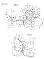
- Fig. 1 is a schematical side view of the applicant's "Sym-Press II" TM press section wherein a control system in accordance with the invention is applied.
- the paper web W is drained on the forming wire 50 of the paper machine, from which said wire the web W is detached on the downwardly inclined run of the wire 50 between the wire suction roll 51 and the wire drive roll 52 at the detaching point P and transferred within the suction zone 53a of the pick-up roll 53 onto the pick-up felt 55, on whose lower face the web W is transferred into the first dewatering press nip N1.
- the first nip N1 is formed between a press-suction roll 54 and a hollow-faced 57 lower press roll 56.
- Two felts run through the nip N1, viz. the lower felt 60 guided by guide rolls 58 and 59, and the pick-up felt 55, which acts as the upper felt in the first nip N1.
- the web W follows along with the upper roll 54 by the effect of the suction zone 54a of the press-suction roll 54, moving into the second dewatering press nip N2, which is formed between the said press-suction roll 54 and the smooth-faced 10 ⁇ central roll 10.
- the diameter D1 of the central roll 10 is substantially larger than the diameters of the other press rolls 54,56,61.
- nip N3 Substantially at the opposite side of the central roll 10, relative the second nip N2, there is a third dewatering press nip N3, through which the press felt 65 runs, guided by the guide rolls 63 and 64.
- the rolls of the nip N3 consist of the central roll 10 and the hollow-faced 62 press roll 61.
- the adhesion properties of the smooth face 10 ⁇ of the central roll 10 are such that, after the second nip N2, the web follows along with the face 10 ⁇ of the central roll 10.
- suction boxes 67 inside the loop of the drying wire 70, which said suction boxes ensure that the web W adheres to the drying wire 70 and passes reliably to the drying section, whose first drying cylinder or a corresponding lead-in cylinder is denoted with the reference numeral 68.
- the detaching of the web W from the smooth face 10 ⁇ of the central roll 10 and its transfer as an open draw W1 or W2 onto the drying wire 70 will be described.
- the detaching angle of the draw W1 is denoted with ⁇ 1 and the corresponding detaching point with R1.
- the detaching angle of the second draw W2 is denoted with ⁇ 2 and the detaching point with R2.
- the detaching orders of the open draws W1 and W2 are denoted with T1 and T2.
- the web tension i.e.
- W E web elongation work
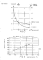
- Fig. 3 shows the dependence of the viscosity and surface tension of water on temperature. As is seen, the surface tension is lowered in a substantially linear way as the temperature is raised, whereas the viscosity is lowered within the temperature range of 0°C to 80°C very steeply, and thereinafter substantially in the same proportion as the surface tension is lowered with a rising temperature.
- the central roll 10 that is used is, as a rule, a roll with a metallic mantle, preferably a roll of a ferromagnetic material, i.e. of a roll material that is preferable to rock material both constructively and in view of the operation.
- a steam box 80 is fitted in connection with the face 10 ⁇ of the central roll 10 between the nips N2 and N3, the temperature of the web W and the temperature and viscosity of the water contained in the web as well as, indirectly, also the temperature of the face 10 ⁇ of the roll 10 being affected by means of steam S in passed into the said steam box 80.
- inductive heating apparatuses 20 are placed substantially in the horizontal plane placed through the centre of rotation of the central roll 10, which said heating apparatuses act, free of contact, through an air gap V, substantially upon the temperature of the thin surface layer of the web face 10 ⁇ .
- a heating medium F in is fed into the roll 10 through a pipe 91 and a connection 90, the said medium being taken out of the roll (F out ) through the same connection 90, or through another connection (not shown) placed in connection with the opposite roll shaft, and a pipe 92.
- the apparatuses for the circulation and heating of the heating medium are denoted schematically with the block 100 in Fig. 1.
- FIG. 1 Even though, in Fig. 1, three different sets of equipment 20;80 and 100 are shown for the heating of the face 10 ⁇ of the central roll 10 and of the web W in view of controlling the draw tension T,T1,T2 of the open draw W0,W1,W2, i.e. the steam box 80, the inductive heating apparatuses 20, and the devices 90,91,92 and 100 for the heating and circulation of the heating medium, in practice, as a rule, all of these means do not have to be used at the same time in one application.
- a granite roll or any other rock roll is not used as the central roll in the press or as any other, corresponding smooth-faced roll, but a metal-mantle roll coated with a metal, a ceramic substance, or with a mixture of same, a cast-iron roll, or an uncoated metal roll, such a roll being constructively preferable to a rock roll of natural material.
- the face 10 ⁇ of a metal roll 10 or equivalent can be heated to a temperature optimal in view of the invention without uncontrolled phenomena of alteration.
- a radiation heater e.g. an infrared heater
- whose construction is in itself known and an exemplifying embodiment of whose construction comes out, e.g., from the applicant's Finnish Patent Application No. 861086, true enough, applied in connection with an airborne web dryer.
- heating apparatuses such as resistance heating or inductive heating.
- An example of heating apparatuses fitted inside the roll and suitable for use in connection with the present invention is described in the applicant's Finnish Patent No. 69,151, whereat the distribution of the temperature in the axial direction of the roll 10 can also be controlled by means of the apparatuses described in the said patent.
- Fig. 4 shows the effect of the steam box 80 on the detaching process.
- the vertical axis represents the detaching angle ⁇ of the open draw as degrees
- the horizontal axis represents the web temperature.
- the curve in Fig. 4 was obtained with the applicant's test paper machine and with newsprint when the web speed was 20 m/s.
- the measurement points in Fig. 4 were obtained with the web W speed of 20 m/s so that, e.g., the difference in speed ⁇ v was kept constant and only the web temperature was varied. From Fig. 1 it can be seen that the detaching angle ⁇ becomes larger when the web W temperature rises.
- inductive heating apparatuses 20 will be described, which are, according to the present estimate, the most advantageous embodiments of the invention both in view of efficiency and in view of a possibility to adjust the transverse profile of the control and heating effect.
- the smooth-faced 10 ⁇ press roll 10 shown in Fig. 5 is the roll from which the web W is detached.
- the roll 10 has a smooth and hard face 10 ⁇ , and it has a cylindrical mantle, which is made of a suitable ferromagnetic material, which has been chosen in consideration of the strength properties of the roll and of the inductive and electromagnetic heating in accordance with the invention.
- the roll 10 is mounted as revolving around its central axis K-K by the intermediate of its ends 11 and axle journals 12. On the axle journals 12 there are bearings, which are fitted in bearing housings. The bearing housings are attached to the supporting frame of the roll, which is placed on a base.
- the roll 10 is arranged as inductively and electromagnetically heatable by means of eddy currents so that the temperature of the face 10 ⁇ of the roll 10 is raised by means of this heating to a considerably high level, as a rule to about 70°C to 100°C.
- component cores 201,202...20 N of an iron core are arranged at the proximity of the roll 10, in the same horizontal line with each other in the axial direction of the roll.
- These component cores 20 n form a magnetic-shoe apparatus 20, which further includes an excitation winding 30, or a winding of its own for each component core (not shown).
- the inductive heating is carried out free of contact so that a small air gap V remains between the iron core and the roll 10 face 10 ⁇ , the magnetic fluxes of the iron core being closed through the said air gap V via the roll 10 mantle, thereby causing a heating effect in it.
- Each component core 20 n is arranged separately displaceable in the radial plane of the roll 10 so as to adjust the magnitude of the active air gap V and, at the same time, the heating capacity.
- each component core is attached to the frame by means of an articulated joint.
- the displacing of the component cores 20 n can be arranged by means of various mechanisms.
- the said air gaps may vary, e.g., within the range of about 1 to 100 mm.
- variable magnetic field produced on the roll 30 is closed between the front face of the iron core and the air gaps V through the mantle of the roll 10.
- This magnetic field induces edddy currents in the surface layer of the roll mantle 10, which said eddy currents generate heat owing to the high resistance in the roll mantle 10.
- I x is the current density at the depth x counted from the mantle face 10 ⁇ , I o is current density on the face 10 ⁇ of the mantle 10, and ⁇ is depth of penetration.
- the depth of penetration has been defined as the depth at which the current density has been lowered to 1/e of the current density I o .
- heating capacities are used which are of the order of 1 to 30 kW/m.
- the smaller the air gap V, the larger is the proportion of the electric power that is passed to the apparatus through the winding 30 which is transferred into the roll mantle 10 to be heated.
- the electric power feeding the induction coil 30 is taken from a 50 Hz three-phase network (3 ⁇ 380 V).
- a rectifier 33 By means of a rectifier 33, the AC current is converted to DC current, which is, by means of an inverter in itself known, based on power electronics, converted to either constant-frequency or variable-frequency (f s ) AC current.
- the adjustment of the positions of the component cores 201...20 N in the iron core 20 can be carried out, e.g., by means of the automatic closed regulating system shown in Fig. 6.
- the adjusting motors are stepping motors 29, which receive their control signals S 1-N from the regulating system 42.
- the regulating system is controlled by a detector device 41, which is, e.g., an apparatus for the measurement of temperature, by means of which the factual values of the surface temperatures T o1 ...T ok of the roll are measured at several different points in the axial direction K-K of the roll 10.
- a detector device 41 which is, e.g., an apparatus for the measurement of temperature, by means of which the factual values of the surface temperatures T o1 ...T ok of the roll are measured at several different points in the axial direction K-K of the roll 10.
- the regulating system 42 includes a set-value unit, by its means it is possible to set the temperature profile in the axial direction K-K of the roll 10 so that an optimal detaching of the web W is obtained.
- the output of the inverter 34 is fed through a matching transformer 35 into a LC resonance circuit.
- the transformer 35 has a primary circuit 35a, an iron core 35b, and a secondary circuit 35c.
- the secondary circuit has n pcs. of taps 451...45 n , which can be connected via a change-over switch 36 to the resonance circuit 37, by means of which the power is fed into the induction coil 30.
- the efficiency of the transfer of heating capacity is at the optimum when the operation takes place at the resonance frequency f r . It has, however, been noticed that, out of several reasons, it is not optimal to operate at the resonance frequency f r and/or simultaneously at both sides of it, but the frequency of operation is chosen within the areas f a1 to f y1 above the resonance frequency f r or correspondingly within the area f a2 to f y2 below the resonance frequency f r .
- a series capacitor C s is used in the RLC circuit.
- the circuit 37 is tuned with basic tuning so that the transmission ratio of the transformer 35 is chosen by means of the switch 36 so that the resonance frequency f r calculated from the formula (6) becomes positioned correctly in accordance with the principles given above.
- Fig. 6 shows a parallel capacitor C r by means of broken lines, which said parallel capacitor can be used in stead of, or along with, a series capacitor C s .
- the resonance frequency f r in a parallel resonance circuit whose induction coil (L) has a resistance R, is calculated as follows:
- the above equation (7) includes a factor dependent on the resistance R.
- a series resonance circuit is preferable, in particular in view of adjustment and control.
- the operating frequency f s is arranged automatically adjusted in accordance with the impedance of the resonance circuit 37 so that the operating frequency f s remains near the resonance frequency f r but, yet, at a safe distance from it, in view of the risk of runaway, i.e. within the areas f y1 ...f a1 or f y2 ...f a2 shown in Fig. 6.
- the measurement of the impendance of the resonance circuit 37 may be based, e.g., on measurement of the current I passing in the circuit.
- This mode of measurement is illustrated in Fig. 6 by the block 46, from which the control signal b is controlled to the regulating unit 47, which alters the frequency f s of the frequency converter 34 on the basis of the control signal b.
- a further mode of measurement of the said impedance which may be an alternative mode or which may be used in addition to the current measurement, is to pass a control signal c from the block 42, from which information can be obtained on the positions of the component cores 20n, i.e. on the air gaps V, which substantially determine the said impedance by acting upon the inductance L.
- An alternative mode of adjustment is to pass feedback signals from the stepping motors 29 into the block 47 and further so as to act upon the output frequency f s of the frequency converter 34.
- the mode of adjustment based on change in frequency can be used either alone in adjusting the temperature profile of the roll 10, or in addition to and together with air-gap adjustment to improve the accuracy and/or rapidity of adjustment.
Landscapes
- Paper (AREA)
- Golf Clubs (AREA)
- Respiratory Apparatuses And Protective Means (AREA)
- Materials For Medical Uses (AREA)
- Replacement Of Web Rolls (AREA)
- Diaphragms For Electromechanical Transducers (AREA)
Priority Applications (1)
| Application Number | Priority Date | Filing Date | Title |
|---|---|---|---|
| AT88850018T ATE70867T1 (de) | 1987-01-23 | 1988-01-15 | Verfahren und vorrichtung im pressteil einer papiermaschine. |
Applications Claiming Priority (2)
| Application Number | Priority Date | Filing Date | Title |
|---|---|---|---|
| FI870308A FI89085C (fi) | 1987-01-23 | 1987-01-23 | Regleringsfoerfarande foer en pappersmaskins pressparti |
| FI870308 | 1987-01-23 |
Publications (3)
| Publication Number | Publication Date |
|---|---|
| EP0276203A2 true EP0276203A2 (de) | 1988-07-27 |
| EP0276203A3 EP0276203A3 (en) | 1989-07-05 |
| EP0276203B1 EP0276203B1 (de) | 1991-12-27 |
Family
ID=8523825
Family Applications (1)
| Application Number | Title | Priority Date | Filing Date |
|---|---|---|---|
| EP88850018A Expired - Lifetime EP0276203B1 (de) | 1987-01-23 | 1988-01-15 | Verfahren und Vorrichtung im Pressteil einer Papiermaschine |
Country Status (6)
| Country | Link |
|---|---|
| US (1) | US4919759A (de) |
| EP (1) | EP0276203B1 (de) |
| AT (1) | ATE70867T1 (de) |
| CA (1) | CA1280634C (de) |
| DE (1) | DE3867072D1 (de) |
| FI (1) | FI89085C (de) |
Cited By (6)
| Publication number | Priority date | Publication date | Assignee | Title |
|---|---|---|---|---|
| US5223099A (en) * | 1988-11-15 | 1993-06-29 | Valmet Paper Machinery Inc. | External heating arrangement for a paper web ceramic coated roll in a paper machine |
| EP0903437A2 (de) * | 1997-09-20 | 1999-03-24 | Voith Sulzer Papiermaschinen Gesellschaft mbH | Verfahren zur Verringerung der Haftung einer feuchten Faserstoffbahn an einer routierenden Walze |
| EP1316644A1 (de) * | 2001-12-03 | 2003-06-04 | Voith Paper Patent GmbH | Verfahren zur Unterstützung der Übergabe einer laufenden Papier-, Karton-, Tissue- oder anderen Faserstoffbahn |
| US6656325B1 (en) * | 1998-05-15 | 2003-12-02 | Metso Paper, Inc. | Machine for manufacturing paper or board |
| US6689993B2 (en) | 2001-03-05 | 2004-02-10 | Metso Automation Oy | Method and device for induction heating a roll |
| WO2020030509A1 (de) * | 2018-08-09 | 2020-02-13 | Voith Patent Gmbh | Pressanordnung |
Families Citing this family (34)
| Publication number | Priority date | Publication date | Assignee | Title |
|---|---|---|---|---|
| US5665206A (en) * | 1991-01-18 | 1997-09-09 | Valmet Corporation | Method and device in a press section of a paper machine for detaching a web from a face of a press roll |
| FI92941C (fi) * | 1991-01-18 | 1995-01-25 | Valmet Paper Machinery Inc | Menetelmä ja laite paperikoneen puristinosalla rainan irrottamiseksi puristintelan pinnalta |
| US5808281A (en) | 1991-04-05 | 1998-09-15 | The Boeing Company | Multilayer susceptors for achieving thermal uniformity in induction processing of organic matrix composites or metals |
| US5728309A (en) | 1991-04-05 | 1998-03-17 | The Boeing Company | Method for achieving thermal uniformity in induction processing of organic matrix composites or metals |
| US5641422A (en) | 1991-04-05 | 1997-06-24 | The Boeing Company | Thermoplastic welding of organic resin composites using a fixed coil induction heater |
| US5723849A (en) | 1991-04-05 | 1998-03-03 | The Boeing Company | Reinforced susceptor for induction or resistance welding of thermoplastic composites |
| US7126096B1 (en) | 1991-04-05 | 2006-10-24 | Th Boeing Company | Resistance welding of thermoplastics in aerospace structure |
| US5624594A (en) | 1991-04-05 | 1997-04-29 | The Boeing Company | Fixed coil induction heater for thermoplastic welding |
| US5410132A (en) * | 1991-10-15 | 1995-04-25 | The Boeing Company | Superplastic forming using induction heating |
| US5645744A (en) | 1991-04-05 | 1997-07-08 | The Boeing Company | Retort for achieving thermal uniformity in induction processing of organic matrix composites or metals |
| US5793024A (en) | 1991-04-05 | 1998-08-11 | The Boeing Company | Bonding using induction heating |
| US5500511A (en) * | 1991-10-18 | 1996-03-19 | The Boeing Company | Tailored susceptors for induction welding of thermoplastic |
| US5508496A (en) * | 1991-10-18 | 1996-04-16 | The Boeing Company | Selvaged susceptor for thermoplastic welding by induction heating |
| US5444220A (en) * | 1991-10-18 | 1995-08-22 | The Boeing Company | Asymmetric induction work coil for thermoplastic welding |
| US5389763A (en) * | 1993-08-02 | 1995-02-14 | Riverdale Of Green, Inc. | Core remover |
| US5710412A (en) * | 1994-09-28 | 1998-01-20 | The Boeing Company | Fluid tooling for thermoplastic welding |
| US5660669A (en) * | 1994-12-09 | 1997-08-26 | The Boeing Company | Thermoplastic welding |
| US5486684A (en) * | 1995-01-03 | 1996-01-23 | The Boeing Company | Multipass induction heating for thermoplastic welding |
| US5573613A (en) * | 1995-01-03 | 1996-11-12 | Lunden; C. David | Induction thermometry |
| US6602810B1 (en) | 1995-06-06 | 2003-08-05 | The Boeing Company | Method for alleviating residual tensile strain in thermoplastic welds |
| US5705795A (en) * | 1995-06-06 | 1998-01-06 | The Boeing Company | Gap filling for thermoplastic welds |
| US5717191A (en) * | 1995-06-06 | 1998-02-10 | The Boeing Company | Structural susceptor for thermoplastic welding |
| US5756973A (en) * | 1995-06-07 | 1998-05-26 | The Boeing Company | Barbed susceptor for improviing pulloff strength in welded thermoplastic composite structures |
| US5829716A (en) * | 1995-06-07 | 1998-11-03 | The Boeing Company | Welded aerospace structure using a hybrid metal webbed composite beam |
| US5556565A (en) * | 1995-06-07 | 1996-09-17 | The Boeing Company | Method for composite welding using a hybrid metal webbed composite beam |
| FI955014A7 (fi) * | 1995-10-20 | 1997-04-21 | Valmet Corp | Paperikoneen puristinosa, jossa käytetään pitkänippipuristinta |
| US5760379A (en) * | 1995-10-26 | 1998-06-02 | The Boeing Company | Monitoring the bond line temperature in thermoplastic welds |
| US5916469A (en) * | 1996-06-06 | 1999-06-29 | The Boeing Company | Susceptor integration into reinforced thermoplastic composites |
| US5869814A (en) * | 1996-07-29 | 1999-02-09 | The Boeing Company | Post-weld annealing of thermoplastic welds |
| US5902935A (en) | 1996-09-03 | 1999-05-11 | Georgeson; Gary E. | Nondestructive evaluation of composite bonds, especially thermoplastic induction welds |
| FI111469B (fi) * | 1996-12-16 | 2003-07-31 | Metso Paper Inc | Menetelmä ja järjestelmä radan irtoamistapahtuman seuraamiseksi |
| US6284089B1 (en) | 1997-12-23 | 2001-09-04 | The Boeing Company | Thermoplastic seam welds |
| FI109235B (fi) * | 1998-04-27 | 2002-06-14 | Fotocomp Oy | Menetelmä paperiradan irtoamiskulman ja/tai -profiilin määrittämiseksi |
| CN106320054A (zh) * | 2015-06-29 | 2017-01-11 | 浙江永泰纸业集团股份有限公司 | 一种低能耗涂布白纸板抄纸工艺 |
Family Cites Families (6)
| Publication number | Priority date | Publication date | Assignee | Title |
|---|---|---|---|---|
| US4351700A (en) * | 1980-06-23 | 1982-09-28 | Dove Norman F | Steam distribution apparatus for the nip of two rolls |
| EP0043289A3 (de) * | 1980-07-02 | 1982-01-20 | Black-Clawson International Limited | Verfahren und Vorrichtung zur Herstellung von Papier und Pappe |
| FI820776A7 (fi) * | 1982-03-05 | 1983-09-06 | Valmet Oy | Paperikoneen puristinosa. |
| FI69151C (fi) * | 1983-10-03 | 1985-12-10 | Valmet Oy | Foerfarande foer reglering av temperaturen av manteln av en vas som anvaends vid framstaellning av papper eller naogon nann banformig produkt samt vals som tillaempar foerfarande it ynnerhet en kalandervals |
| SE441017B (sv) * | 1984-01-19 | 1985-09-02 | Wiberg Per Arne | Forfarande och anordning for torkning av en fuktig fiberbana |
| US4738752A (en) * | 1986-08-12 | 1988-04-19 | Beloit Corporation | Heated extended nip press apparatus |
-
1987
- 1987-01-23 FI FI870308A patent/FI89085C/fi not_active IP Right Cessation
-
1988
- 1988-01-15 EP EP88850018A patent/EP0276203B1/de not_active Expired - Lifetime
- 1988-01-15 DE DE8888850018T patent/DE3867072D1/de not_active Expired - Lifetime
- 1988-01-15 AT AT88850018T patent/ATE70867T1/de not_active IP Right Cessation
- 1988-01-22 CA CA000557176A patent/CA1280634C/en not_active Expired - Lifetime
- 1988-01-25 US US07/147,457 patent/US4919759A/en not_active Expired - Lifetime
Cited By (9)
| Publication number | Priority date | Publication date | Assignee | Title |
|---|---|---|---|---|
| US5223099A (en) * | 1988-11-15 | 1993-06-29 | Valmet Paper Machinery Inc. | External heating arrangement for a paper web ceramic coated roll in a paper machine |
| EP0903437A2 (de) * | 1997-09-20 | 1999-03-24 | Voith Sulzer Papiermaschinen Gesellschaft mbH | Verfahren zur Verringerung der Haftung einer feuchten Faserstoffbahn an einer routierenden Walze |
| US6656325B1 (en) * | 1998-05-15 | 2003-12-02 | Metso Paper, Inc. | Machine for manufacturing paper or board |
| US6689993B2 (en) | 2001-03-05 | 2004-02-10 | Metso Automation Oy | Method and device for induction heating a roll |
| AT412789B (de) * | 2001-03-05 | 2005-07-25 | Metso Automation Oy | Verfahren und vorrichtung zum erwärmen einer walze |
| EP1316644A1 (de) * | 2001-12-03 | 2003-06-04 | Voith Paper Patent GmbH | Verfahren zur Unterstützung der Übergabe einer laufenden Papier-, Karton-, Tissue- oder anderen Faserstoffbahn |
| WO2020030509A1 (de) * | 2018-08-09 | 2020-02-13 | Voith Patent Gmbh | Pressanordnung |
| CN112424421A (zh) * | 2018-08-09 | 2021-02-26 | 福伊特专利有限公司 | 压榨装置 |
| EP3833816B1 (de) | 2018-08-09 | 2024-09-11 | Voith Patent GmbH | Pressanordnung |
Also Published As
| Publication number | Publication date |
|---|---|
| EP0276203B1 (de) | 1991-12-27 |
| EP0276203A3 (en) | 1989-07-05 |
| FI89085C (fi) | 1993-08-10 |
| US4919759A (en) | 1990-04-24 |
| FI870308A0 (fi) | 1987-01-23 |
| CA1280634C (en) | 1991-02-26 |
| DE3867072D1 (de) | 1992-02-06 |
| FI89085B (fi) | 1993-04-30 |
| FI870308L (fi) | 1988-07-24 |
| ATE70867T1 (de) | 1992-01-15 |
Similar Documents
| Publication | Publication Date | Title |
|---|---|---|
| EP0276203B1 (de) | Verfahren und Vorrichtung im Pressteil einer Papiermaschine | |
| EP0276202B1 (de) | Verfahren und Vorrichtung im Pressteil einer Papiermaschine zum Ablösen der Bahn von der Presswalze | |
| EP0159337B2 (de) | Verfahren und vorrichtung zum elektromagnetischen aufwärmen einer rolle, vorzugsweise einer kalanderrolle verwendet bei der papierherstellung oder sonstigem blattförmigen erzeugnis | |
| EP0337973B1 (de) | Verfahren und Vorrichtungen zur Druckbehandlung einer Papierbahn | |
| US4631794A (en) | Apparatus and method for eddy current heating a roll in a paper machine | |
| FI71374C (fi) | Foerfarande och anordning vid kalandrering av en bana | |
| FI74826B (fi) | Foerfarande och anordning foer behandling av ett banmaterial. | |
| EP0568404B1 (de) | Verfahren zur Behandlung von Fasern zur Herstellung von Tissue-Papier | |
| KR20010042534A (ko) | 롤사이의 접촉 압력을 조절하는 자기 장치를 가진 캘린더 | |
| FI73260B (fi) | Foerfarande och anordning foer elektromagnetisk uppvaermning av en vals, i synnerhet en kalandervals som anvaends vid framstaellning av papper eller naogon annan banformig produkt. | |
| US20020092847A1 (en) | Method and device for heating a roll | |
| FI84739B (fi) | Foerfarande och anordning vid pressbehandling av fiberbana. | |
| FI88419B (fi) | Bk-vals med uppvaermd mantel | |
| FI82730B (fi) | Foerfarande och anordning foer avvattning av en pappers- eller kartongbana. | |
| WO2001068979A1 (en) | Thermoroll with a thin flexible shell and a nip formed between the thermoroll and a soft covered roll | |
| CA2147687A1 (en) | Method of treating papermaking fibers for making tissue |
Legal Events
| Date | Code | Title | Description |
|---|---|---|---|
| PUAI | Public reference made under article 153(3) epc to a published international application that has entered the european phase |
Free format text: ORIGINAL CODE: 0009012 |
|
| AK | Designated contracting states |
Kind code of ref document: A2 Designated state(s): AT CH DE ES FR GB IT LI SE |
|
| PUAL | Search report despatched |
Free format text: ORIGINAL CODE: 0009013 |
|
| AK | Designated contracting states |
Kind code of ref document: A3 Designated state(s): AT CH DE ES FR GB IT LI SE |
|
| 17P | Request for examination filed |
Effective date: 19891012 |
|
| 17Q | First examination report despatched |
Effective date: 19910226 |
|
| GRAA | (expected) grant |
Free format text: ORIGINAL CODE: 0009210 |
|
| AK | Designated contracting states |
Kind code of ref document: B1 Designated state(s): AT CH DE ES FR GB IT LI SE |
|
| PG25 | Lapsed in a contracting state [announced via postgrant information from national office to epo] |
Ref country code: IT Free format text: LAPSE BECAUSE OF FAILURE TO SUBMIT A TRANSLATION OF THE DESCRIPTION OR TO PAY THE FEE WITHIN THE PRE;WARNING: LAPSES OF ITALIAN PATENTS WITH EFFECTIVE DATE BEFORE 2007 MAY HAVE OCCURRED AT ANY TIME BEFORE 2007. THE CORRECT EFFECTIVE DATE MAY BE DIFFERENT FROM THE ONE RECORDED.SCRIBED TIME-LIMIT Effective date: 19911227 Ref country code: LI Effective date: 19911227 Ref country code: CH Effective date: 19911227 Ref country code: ES Free format text: THE PATENT HAS BEEN ANNULLED BY A DECISION OF A NATIONAL AUTHORITY Effective date: 19911227 |
|
| REF | Corresponds to: |
Ref document number: 70867 Country of ref document: AT Date of ref document: 19920115 Kind code of ref document: T |
|
| REF | Corresponds to: |
Ref document number: 3867072 Country of ref document: DE Date of ref document: 19920206 |
|
| REG | Reference to a national code |
Ref country code: CH Ref legal event code: PL |
|
| EN | Fr: translation not filed | ||
| PG25 | Lapsed in a contracting state [announced via postgrant information from national office to epo] |
Ref country code: FR Effective date: 19920522 |
|
| PLBE | No opposition filed within time limit |
Free format text: ORIGINAL CODE: 0009261 |
|
| STAA | Information on the status of an ep patent application or granted ep patent |
Free format text: STATUS: NO OPPOSITION FILED WITHIN TIME LIMIT |
|
| 26N | No opposition filed | ||
| REG | Reference to a national code |
Ref country code: FR Ref legal event code: ST |
|
| EAL | Se: european patent in force in sweden |
Ref document number: 88850018.8 |
|
| PGFP | Annual fee paid to national office [announced via postgrant information from national office to epo] |
Ref country code: GB Payment date: 20011214 Year of fee payment: 15 |
|
| PGFP | Annual fee paid to national office [announced via postgrant information from national office to epo] |
Ref country code: DE Payment date: 20011217 Year of fee payment: 15 |
|
| PGFP | Annual fee paid to national office [announced via postgrant information from national office to epo] |
Ref country code: AT Payment date: 20011228 Year of fee payment: 15 |
|
| REG | Reference to a national code |
Ref country code: GB Ref legal event code: IF02 |
|
| PGFP | Annual fee paid to national office [announced via postgrant information from national office to epo] |
Ref country code: SE Payment date: 20020102 Year of fee payment: 15 |
|
| PG25 | Lapsed in a contracting state [announced via postgrant information from national office to epo] |
Ref country code: GB Free format text: LAPSE BECAUSE OF NON-PAYMENT OF DUE FEES Effective date: 20030115 Ref country code: AT Free format text: LAPSE BECAUSE OF NON-PAYMENT OF DUE FEES Effective date: 20030115 |
|
| PG25 | Lapsed in a contracting state [announced via postgrant information from national office to epo] |
Ref country code: SE Free format text: LAPSE BECAUSE OF NON-PAYMENT OF DUE FEES Effective date: 20030116 |
|
| PG25 | Lapsed in a contracting state [announced via postgrant information from national office to epo] |
Ref country code: DE Free format text: LAPSE BECAUSE OF NON-PAYMENT OF DUE FEES Effective date: 20030801 |
|
| EUG | Se: european patent has lapsed | ||
| GBPC | Gb: european patent ceased through non-payment of renewal fee |