EP0276434A1 - Agencement de circuit pour la recherche d'un vecteur de mouvement pendant l'analyse numérique d'une image - Google Patents
Agencement de circuit pour la recherche d'un vecteur de mouvement pendant l'analyse numérique d'une image Download PDFInfo
- Publication number
- EP0276434A1 EP0276434A1 EP87118283A EP87118283A EP0276434A1 EP 0276434 A1 EP0276434 A1 EP 0276434A1 EP 87118283 A EP87118283 A EP 87118283A EP 87118283 A EP87118283 A EP 87118283A EP 0276434 A1 EP0276434 A1 EP 0276434A1
- Authority
- EP
- European Patent Office
- Prior art keywords
- arithmetic unit
- memory
- circuit arrangement
- arrangement according
- array
- Prior art date
- Legal status (The legal status is an assumption and is not a legal conclusion. Google has not performed a legal analysis and makes no representation as to the accuracy of the status listed.)
- Ceased
Links
Images


Classifications
-
- H—ELECTRICITY
- H04—ELECTRIC COMMUNICATION TECHNIQUE
- H04N—PICTORIAL COMMUNICATION, e.g. TELEVISION
- H04N19/00—Methods or arrangements for coding, decoding, compressing or decompressing digital video signals
- H04N19/50—Methods or arrangements for coding, decoding, compressing or decompressing digital video signals using predictive coding
- H04N19/503—Methods or arrangements for coding, decoding, compressing or decompressing digital video signals using predictive coding involving temporal prediction
- H04N19/51—Motion estimation or motion compensation
-
- G—PHYSICS
- G06—COMPUTING OR CALCULATING; COUNTING
- G06T—IMAGE DATA PROCESSING OR GENERATION, IN GENERAL
- G06T7/00—Image analysis
- G06T7/20—Analysis of motion
- G06T7/223—Analysis of motion using block-matching
- G06T7/231—Analysis of motion using block-matching using full search
Definitions
- the invention relates to an arrangement for displacement vector search in digital image analysis according to the preamble of patent claim 1.
- Prediction coding methods are used to transmit video phone scenes at transmission rates between 64 kBit / s and 384 kBit / s.
- the prediction coding uses the information already available at the receiver to describe the current picture with as little information as possible.
- the prediction coding is significantly improved if the picture-to-picture changes due to movements in the scene spatially and temporally recorded and included in the calculation of the predicted image (prediction coding with motion compensation).
- Known methods for motion compensation are the block-wise motion compensation described for example in EP 0 123 616 and the object-related motion compensation described for example in DE-OS 33 28 341.
- the method has in common that two images, consisting of digitized pixels for luminance and chrominance, are compared with one another essentially pixel by pixel. For this purpose, the digitized images are divided into regular block grids.
- the entire image to be predicted is processed schematically (iconic image processing), with each block of the regular (n ⁇ n) block grid being assigned the image-to-image shift for which a distance measure or a similarity measure between the gray value mountains of the (current) block under consideration and the gray value mountains of a correspondingly shifted block in the previous image is a minimum or a maximum.
- adjacent moving (shifted) blocks are combined into so-called objects and their movement is described by at least one motion vector (displacement vector) of an object which characterizes the object motion.
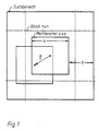
- a concentric subset of the block consisting of consists of, as shown in FIG. 1, in the current image s ⁇ s (s ⁇ n) pixels, recorded and in the previous image for a subset of s ⁇ s pixels of equal size (hereinafter referred to as the measurement window) as the distance measure, the sum of the differences in magnitude educated.
- the digitized gray value of the pixel in the current image is denoted by a ik
- the digitized gray value of the pixel in the previous image by b ik .
- a search area is defined which extends around ⁇ q pixels in the x and y directions concentrically around the undisplaced measurement window.
- the minimum distance dimension to be found is one of the 4 ⁇ q2 possible values
- the indices 1 and m are a function of the displacement of the measuring window.
- a subset selected according to a predetermined pattern can also be used, so that fewer arithmetic operations have to be carried out.
- V d V dmin of these values
- a vector is defined which points from the center of the block in the current image to the center of the shifted measurement window and is the shifting of a block in two successive images.
- This vector is called the displacement vector referred to and the method described for finding the minimum distance dimension of two blocks as a displacement vector search.
- the invention is based on the object of determining the values V d and determining the displacement vector with an electronic arrangement in the form of a monolithic integrated circuit in real time.
- the object is achieved by the features specified in the characterizing part of claim 1.
- the arrangement is essentially characterized by parallel processing and formation of the respective difference in amount between associated pixels in the current and previous image.
- Advantageous refinements and developments of the invention are specified in the subclaims.
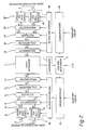
- FIG. 2 The block diagram of the arrangement for the displacement vector search is shown in FIG. 2.
- a control arithmetic unit 3 is connected to an array arithmetic unit 1 via an accumulator 2.
- the control arithmetic unit has a connection for input and output of data and is connected to 2 program memories 11L and 11R. These each have a data input for program input and a data output for addresses.
- the output for addresses is connected to an instruction decoder 10L or 10R.
- the outputs of the instruction decoders 10L and 10R lead to a memory 8L or 8R for the search area, to a memory 9L or 9R for the measurement window, to a first pipeline register 7L or 7R, to a multiplexer 6L or 6R , to a cyclic permutator 5L or 5R and to a second pipeline register 4L or 4R.
- the memories 8L and 9L or 8R and 9R are each connected to the external image memories via eight lines, in each of which the complete images for which the displacement vectors are to be determined are stored.
- 64 output lines each of the memories 8L and 9L and 8R and 9R lead to the first pipeline registers 7L and 7R, respectively.
- 128 output lines each from the pipeline registers 7L and 7R lead to the multiplexers 6L and 6R.
- 64 output lines each of the multiplexers 6L and 6R lead to the cyclic permutators 5L and 5R.
- 64 output lines each of the cyclic permutators 5L and 5R lead to the second pipeline registers 4L and 4R, and 64 output lines each of the pipeline registers 4L and 4R lead to the array arithmetic unit 1.
- the array arithmetic unit 1 is used to carry out the mathematical operation ⁇
- the values calculated by the array arithmetic unit 1 are accumulated for a search step, ie for the corresponding size of the measurement window. These values are passed on to the control arithmetic unit 3, in which the displacement vector is determined from the minimum of the distance dimension V dmin , as explained in the introduction to the description.
- the data (here gray values of the pixels of eight bits each) are read into the memories for the search area and the measurement window 8L, 9L, 8R, 9R from external image memories with random access (RAM), in which complete images are stored, pixel by pixel.
- RAM random access
- the reading out of the memories 8L, 9L, 8R, 9R takes place in each case as a 64 bit wide data word, the data from eight adjacent pixels being read out in parallel and chained together.
- the arrangement works in a reciprocal mode (memory change mode) on two memories each for the search area and the measurement window. While the data from external image memories are written into the memory 8L for the search area and the memory 9R for the measurement window, the data from the memory 8R for the search area and the memory 9L for the measurement window are read out and processed at the same time. These storage functions change with each successive search step.
- the multiplexers 6L, 6R are used to switch the data paths in the memory change operation mentioned.
- the cyclic permutators 5L, 5R cyclically rearrange 4 bytes each in groups of 2 x 4 bytes. The possibility of this cyclical rearrangement is necessary in order to correctly subtract the data of the pixels of the current and the previous image from one another, since, due to the memory organization, the data read from the memories are also cyclically interchanged.
- the pipeline registers 4L, 7L, 4R, 7R serve to increase the data throughput rate in a manner known per se. Depending on the circuitry and technological implementation, they can either be omitted or their number changed and / or implemented elsewhere in the arrangement.
- a control is part of the arrangement. In the exemplary embodiment, it consists of instruction decoder 10L, 10R, program memory 11L, 11R and control arithmetic unit 3. These circuits can also be combined in a control unit.
- the controller can advantageously be programmed for different motion vector search algorithms.
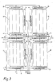
- the memory consists of four memory matrices 81 to 84, each of which is provided with a column decoder 21, 22, 23 or 24, a row decoder 31, 32, 33 or 34 and a sense amplifier 41, 42, 43 or 44.
- the data is written from the external image memory via line 13.
- Data selection circuits 51 and 42 controlled by the instruction decoder 10L (FIG. 2) via lines 12 each select 32 bits from the 64 bits of the decoded data addressed in columns in the right and left memory matrices via lines 12, which are transmitted via lines 14 to Pipeline register 7L (Fig. 2) are routed.
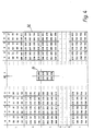
- FIGS. 4 and 5 show a functional example for storing the search area, for example in the memory 8L.
- a numerical assignment is made between a measurement area comprising 28 ⁇ 28 pixels and the physical memory cell, for example in the memory 8L.
- the position of the four memory matrices 81 to 84 of the memory 8L is designated L (left), R (right), O (top) and U (bottom) in FIGS. 4 and 5.
- the pixel data is stored in such a way that for reading out eight neighboring pixels (framed area B in FIG. 4), arranged in a 2 ⁇ 4 matrix (2 pixels horizontally, 4 pixels vertically), only one column in each of the four memory matrices is selected by the column decoders 21 to 24 (Fig. 3).
- the selection of the lines of the gray scale values of the pixel data digitized in 8 bit word widths is carried out via the data selection circuits 51 and 52 connected to the sense amplifiers 41 to 44.
- FIG. 6 shows the sum formation in the array arithmetic unit 1 as a flow chart.
- the respective results are denoted by s11 to s14.
- FIG. 7 shows a circuit for forming the difference in the amount of two 8-bit gray values, as it occurs in each of the links 51 to 58 of FIG. 6, for example for the link 55, in detail.
- the 8 bits a0 to a7 aB of the gray value a21 are the first inputs and the inverted 8 bits to For example, the gray value b21 the second inputs of the eight full adders 511 to 518 fed.
- the respective outputs of the carrier bits (carry bits) c0 to c6 of the full adder 511 to 517 are each connected to the carrier bit inputs of the adjacent full adder.
- the output for the carrier bit c6 is connected via an inverter 531 to all the first inputs of eight exclusive-OR gates 521 to 528 and to the carrier bit input of a full adder 541 from eight further full adders 541 to 548.
- the outputs of the exclusive-OR gates 521 to 528 are each connected to eight first inputs of the 8 further full adders 541 to 548, the second input of which is supplied with one bit of the difference in amount s 1 and 1 (in the case of the links 51 to 54, this input is on the binary value "O" switched).
- the individual outputs of the sum s21 are taken from the eight outputs of the full adders 541 to 548.
- the remaining adders 59 to 61 correspond to the prior art, so that their description is unnecessary.
- the search step addresses for the arrangement shown in FIG. 2 are generated by means of the program memories 11L and 11R and the desired pixel data (gray values) are thus read in and processed in the array arithmetic unit.
- the control arithmetic unit 3 As soon as the smallest value of the output of the adder 61 and its associated address can be found by the control arithmetic unit 3 after a predetermined number of displacement vector searches, the components of the displacement vector are output by the control arithmetic unit.
Landscapes
- Engineering & Computer Science (AREA)
- Multimedia (AREA)
- Computer Vision & Pattern Recognition (AREA)
- Physics & Mathematics (AREA)
- General Physics & Mathematics (AREA)
- Theoretical Computer Science (AREA)
- Signal Processing (AREA)
- Image Analysis (AREA)
- Image Processing (AREA)
Applications Claiming Priority (4)
| Application Number | Priority Date | Filing Date | Title |
|---|---|---|---|
| DE3644407 | 1986-12-24 | ||
| DE3644407 | 1986-12-24 | ||
| DE19873721074 DE3721074A1 (de) | 1986-12-24 | 1987-06-26 | Schaltungsanordnung zur verschiebungsvektorsuche in der digitalen bildanalyse |
| DE3721074 | 1987-06-26 |
Publications (1)
| Publication Number | Publication Date |
|---|---|
| EP0276434A1 true EP0276434A1 (fr) | 1988-08-03 |
Family
ID=25850853
Family Applications (1)
| Application Number | Title | Priority Date | Filing Date |
|---|---|---|---|
| EP87118283A Ceased EP0276434A1 (fr) | 1986-12-24 | 1987-12-10 | Agencement de circuit pour la recherche d'un vecteur de mouvement pendant l'analyse numérique d'une image |
Country Status (3)
| Country | Link |
|---|---|
| US (1) | US4800425A (fr) |
| EP (1) | EP0276434A1 (fr) |
| DE (1) | DE3721074A1 (fr) |
Cited By (6)
| Publication number | Priority date | Publication date | Assignee | Title |
|---|---|---|---|---|
| FR2638924A1 (fr) * | 1988-11-09 | 1990-05-11 | Artieri Alain | Procede et circuit de traitement par bloc de signal bidimensionnel d'images animees |
| EP0415737A3 (en) * | 1989-08-29 | 1993-11-03 | Sony Corp | Motion detecting circuits for video images |
| EP0488795A3 (fr) * | 1990-11-30 | 1994-02-23 | Sony Corp | |
| EP0497586A3 (en) * | 1991-01-31 | 1994-05-18 | Sony Corp | Motion detection circuit |
| EP0613299A3 (fr) * | 1993-02-25 | 1995-02-15 | Ind Tech Res Inst | Architecture à bus dual pour la compensation de mouvement. |
| FR2723796A1 (fr) * | 1994-08-19 | 1996-02-23 | Thomson Consumer Electronics | Dispositif d'estimation de mouvement |
Families Citing this family (15)
| Publication number | Priority date | Publication date | Assignee | Title |
|---|---|---|---|---|
| GB8722612D0 (en) * | 1987-09-25 | 1987-11-04 | British Telecomm | Motion estimator |
| FR2627926A1 (fr) * | 1988-02-29 | 1989-09-01 | Labo Electronique Physique | Procede et dispositif de codage de signaux video numeriques, et dispositif de decodage correspondant |
| US4897720A (en) * | 1988-03-14 | 1990-01-30 | Bell Communications Research, Inc. | Circuit implementation of block matching algorithm |
| US5031037A (en) * | 1989-04-06 | 1991-07-09 | Utah State University Foundation | Method and apparatus for vector quantizer parallel processing |
| US4958225A (en) * | 1989-06-09 | 1990-09-18 | Utah State University Foundation | Full-search-equivalent method for matching data and a vector quantizer utilizing such method |
| US5091783A (en) * | 1990-03-01 | 1992-02-25 | Texas Instruments Incorporated | Still more feature for improved definition television digital processing units, systems, and methods |
| US5093722A (en) * | 1990-03-01 | 1992-03-03 | Texas Instruments Incorporated | Definition television digital processing units, systems and methods |
| US5091786A (en) * | 1990-03-01 | 1992-02-25 | Texas Instruments Incorporated | Multi-screen feature for improved definition television digital processing units, systems, and methods |
| DE4015390A1 (de) * | 1990-05-14 | 1991-11-21 | Nokia Unterhaltungselektronik | Verfahren zum berechnen des inhalts eines zwischenbildes zu jeweils zwei aufeinanderfolgenden monitorbildern |
| JPH0453389A (ja) * | 1990-06-21 | 1992-02-20 | Graphics Commun Technol:Kk | 動ベクトル検出装置 |
| EP0474276B1 (fr) * | 1990-09-03 | 1997-07-23 | Koninklijke Philips Electronics N.V. | Evaluation de vecteur de mouvement d'image vidéo mettant en oeuvre un région asymétrique de mise à jour |
| SE469866B (sv) * | 1991-04-12 | 1993-09-27 | Dv Sweden Ab | Metod för estimering av rörelseinnehåll i videosignaler |
| US5408328A (en) * | 1992-03-23 | 1995-04-18 | Ricoh Corporation, California Research Center | Compressed image virtual editing system |
| US5327248A (en) * | 1992-03-23 | 1994-07-05 | Ricoh Company, Ltd. | Compressed image virtual editing system |
| DE10120140C2 (de) * | 2001-04-25 | 2003-03-13 | Sci Worx Gmbh | Verfahren zum Zugriff auf Suchbilddaten bei der Bewegungsschätzung |
Citations (3)
| Publication number | Priority date | Publication date | Assignee | Title |
|---|---|---|---|---|
| US4460923A (en) * | 1981-06-01 | 1984-07-17 | Nippon Electric Co., Ltd. | Predictive coding system for television signals |
| US4562468A (en) * | 1982-05-14 | 1985-12-31 | Nec Corporation | Adaptive predictive coding apparatus of television signal |
| EP0180446A2 (fr) * | 1984-10-27 | 1986-05-07 | Sony Corporation | Procédés pour la détection du mouvement dans des images de télévision |
Family Cites Families (5)
| Publication number | Priority date | Publication date | Assignee | Title |
|---|---|---|---|---|
| US3632865A (en) * | 1969-12-23 | 1972-01-04 | Bell Telephone Labor Inc | Predictive video encoding using measured subject velocity |
| JPS4929716A (fr) * | 1972-07-19 | 1974-03-16 | ||
| JPS5244512A (en) * | 1975-10-06 | 1977-04-07 | Nippon Telegr & Teleph Corp <Ntt> | Between-frame coding equipment |
| DE3328341A1 (de) * | 1983-08-05 | 1985-02-14 | Licentia Patent-Verwaltungs-Gmbh, 6000 Frankfurt | Verfahren zur videosignalcodierung |
| US6370265B1 (en) * | 1999-11-24 | 2002-04-09 | Direct Radiography Corp. | Method for generating gray scale transfer functions for use in displaying a digital radiogram |
-
1987
- 1987-06-26 DE DE19873721074 patent/DE3721074A1/de not_active Withdrawn
- 1987-12-10 EP EP87118283A patent/EP0276434A1/fr not_active Ceased
- 1987-12-18 US US07/134,872 patent/US4800425A/en not_active Expired - Fee Related
Patent Citations (3)
| Publication number | Priority date | Publication date | Assignee | Title |
|---|---|---|---|---|
| US4460923A (en) * | 1981-06-01 | 1984-07-17 | Nippon Electric Co., Ltd. | Predictive coding system for television signals |
| US4562468A (en) * | 1982-05-14 | 1985-12-31 | Nec Corporation | Adaptive predictive coding apparatus of television signal |
| EP0180446A2 (fr) * | 1984-10-27 | 1986-05-07 | Sony Corporation | Procédés pour la détection du mouvement dans des images de télévision |
Non-Patent Citations (4)
| Title |
|---|
| ELECTRONICS AND COMMUNICATIONS IN JAPAN, 1, Band 69, Nr. 4, Teil 1, April 1986, Seiten 65-74, Scripta Technica, Inc.; H. KURODA et al.: "An interframe coding system using motion-compensation prediction and uncovered background prediction" * |
| IEEE INTERNATIONAL CONFERENCE ON ACOUSTICS, SPEECH AND SIGNAL PROCESSING, Band 1, 26.-29. März 1985, Seiten 359-362, IEEE, New York, US; K.-H. TZOU et al.: "Block-recursive matching algorithm (BRMA) for displacement estimation of video images" * |
| IEEE TRANSACTIONS ON COMMUNICATIONS, Band COM-33, Nr. 8, August 1985, Seiten 888-896, IEEE, New York, US; R. SRINIVASAN et al.: "Predictive coding based on efficient motion estimation" * |
| THE 8TH ANNUAL SYMPOSIUM ON COMPUTER ARCHITECTURE, 12.-14. Mai 1981, Seiten 21-35, Minneapolis, Minnesota, US; D.P. AGRAWAL: "A pipelined pseudoparallel system architecture for motion analysis" * |
Cited By (11)
| Publication number | Priority date | Publication date | Assignee | Title |
|---|---|---|---|---|
| FR2638924A1 (fr) * | 1988-11-09 | 1990-05-11 | Artieri Alain | Procede et circuit de traitement par bloc de signal bidimensionnel d'images animees |
| EP0369854A1 (fr) * | 1988-11-09 | 1990-05-23 | France Telecom Sa | Procédé et circuit de traitement par bloc de signal bidimensionnel d'images animées |
| US5099325A (en) * | 1988-11-09 | 1992-03-24 | Etat Francais Represente Par Le Ministre Des Postes, Telecommunications Et De L'espace (Centre National D'etudes Des Telecommunications Cnet) | Process and circuit for block matching in two-dimensional picture signals |
| EP0415737A3 (en) * | 1989-08-29 | 1993-11-03 | Sony Corp | Motion detecting circuits for video images |
| EP0488795A3 (fr) * | 1990-11-30 | 1994-02-23 | Sony Corp | |
| EP0497586A3 (en) * | 1991-01-31 | 1994-05-18 | Sony Corp | Motion detection circuit |
| EP0613299A3 (fr) * | 1993-02-25 | 1995-02-15 | Ind Tech Res Inst | Architecture à bus dual pour la compensation de mouvement. |
| US5485214A (en) * | 1993-02-25 | 1996-01-16 | Industrial Technology Research Institute | Dual bus dual bank architecture for motion compensation |
| FR2723796A1 (fr) * | 1994-08-19 | 1996-02-23 | Thomson Consumer Electronics | Dispositif d'estimation de mouvement |
| EP0702327A1 (fr) * | 1994-08-19 | 1996-03-20 | THOMSON multimedia | Dispositif d'estimation de mouvement |
| US5745605A (en) * | 1994-08-19 | 1998-04-28 | Deutsche Thomson Brandt Gmbh | Device for estimation of movement |
Also Published As
| Publication number | Publication date |
|---|---|
| DE3721074A1 (de) | 1988-07-07 |
| US4800425A (en) | 1989-01-24 |
Similar Documents
| Publication | Publication Date | Title |
|---|---|---|
| EP0276434A1 (fr) | Agencement de circuit pour la recherche d'un vecteur de mouvement pendant l'analyse numérique d'une image | |
| DE69208737T2 (de) | Schaltung zur Interpolation eines Bildsignals | |
| DE69520974T2 (de) | Eine integrierte Halbleiterschaltung | |
| DE3202365C2 (de) | Datenspeicher mit Fensterabtastung | |
| DE3114643C2 (fr) | ||
| DE4123713C2 (de) | Korrelationsdetektor für Bilder | |
| DE3804938C2 (de) | Bildverarbeitungseinrichtung | |
| DE3751841T2 (de) | Verfahren zur Glättung von Bildsignalen | |
| DE60109858T2 (de) | System zur Ungleichheitsmessung von stereoskopischen Bildern | |
| DE2747075C2 (de) | Speicheranordnung mit Anordnung zur Speichersteuerung für Bildverarbeitungsoperationen | |
| DE2640157C2 (de) | Verfahren und Anordnung zum redundanzvermindernden Codieren von Bildern | |
| DE69122226T2 (de) | Verfahren und Einrichtung zur Zugriffsanordnung eines VRAM zum beschleunigten Schreiben von vertikalen Linien auf einer Anzeige | |
| DE3750017T2 (de) | Prozessor für orthogonale Transformation. | |
| DE3415470A1 (de) | Geraet und verfahren zum codieren und speichern von rasterabtastbildern | |
| DE2340597A1 (de) | Bildverarbeitungsanordnung | |
| DE3318303C2 (fr) | ||
| DE69325487T2 (de) | Bild Prozessor und Verfahren | |
| DE2754687A1 (de) | Korrelationsanordnung | |
| DE3632639C2 (de) | Einrichtung zum Hochgeschwindigkeitsverarbeiten von Bilddaten durch Faltung | |
| DE3503400C2 (fr) | ||
| DE3437895C2 (fr) | ||
| DE3751312T2 (de) | Verfahren und Einrichtung zur Verarbeitung von Bilddaten. | |
| DE4234985C2 (de) | Verfahren zum Transformieren von Farbsignalen und Vorrichtung zur Durchführung des Verfahrens | |
| DE68923110T2 (de) | Vermeiden des Verschwindens von dünnen Linien in Bildreduzierverfahren. | |
| DE3713627A1 (de) | Bildspeicherschaltung, insbesondere zur verwendung beim drehen von bilddaten |
Legal Events
| Date | Code | Title | Description |
|---|---|---|---|
| PUAI | Public reference made under article 153(3) epc to a published international application that has entered the european phase |
Free format text: ORIGINAL CODE: 0009012 |
|
| AK | Designated contracting states |
Kind code of ref document: A1 Designated state(s): AT BE CH DE ES FR GB IT LI LU NL SE |
|
| 17P | Request for examination filed |
Effective date: 19890119 |
|
| 17Q | First examination report despatched |
Effective date: 19910729 |
|
| STAA | Information on the status of an ep patent application or granted ep patent |
Free format text: STATUS: THE APPLICATION HAS BEEN REFUSED |
|
| 18R | Application refused |
Effective date: 19920608 |
|
| RIN1 | Information on inventor provided before grant (corrected) |
Inventor name: SCHWERZEL, WOLFGANG, DR. RER. NAT. Inventor name: KUMMERFELDT, GEORG, DIPL.-ING. |