EP0276513B1 - Eindringdetektions- und Strassenfahrzeug-Identifizierungsvorrichtung - Google Patents
Eindringdetektions- und Strassenfahrzeug-Identifizierungsvorrichtung Download PDFInfo
- Publication number
- EP0276513B1 EP0276513B1 EP87202558A EP87202558A EP0276513B1 EP 0276513 B1 EP0276513 B1 EP 0276513B1 EP 87202558 A EP87202558 A EP 87202558A EP 87202558 A EP87202558 A EP 87202558A EP 0276513 B1 EP0276513 B1 EP 0276513B1
- Authority
- EP
- European Patent Office
- Prior art keywords
- detector
- reference plane
- distance
- vehicles
- few
- Prior art date
- Legal status (The legal status is an assumption and is not a legal conclusion. Google has not performed a legal analysis and makes no representation as to the accuracy of the status listed.)
- Expired - Lifetime
Links
Images

Classifications
-
- G—PHYSICS
- G08—SIGNALLING
- G08B—SIGNALLING SYSTEMS, e.g. PERSONAL CALLING SYSTEMS; ORDER TELEGRAPHS; ALARM SYSTEMS
- G08B13/00—Burglar, theft or intruder alarms
- G08B13/18—Actuation by interference with heat, light, or radiation of shorter wavelength; Actuation by intruding sources of heat, light, or radiation of shorter wavelength
- G08B13/189—Actuation by interference with heat, light, or radiation of shorter wavelength; Actuation by intruding sources of heat, light, or radiation of shorter wavelength using passive radiation detection systems
- G08B13/19—Actuation by interference with heat, light, or radiation of shorter wavelength; Actuation by intruding sources of heat, light, or radiation of shorter wavelength using passive radiation detection systems using infrared-radiation detection systems
- G08B13/193—Actuation by interference with heat, light, or radiation of shorter wavelength; Actuation by intruding sources of heat, light, or radiation of shorter wavelength using passive radiation detection systems using infrared-radiation detection systems using focusing means
-
- G—PHYSICS
- G08—SIGNALLING
- G08G—TRAFFIC CONTROL SYSTEMS
- G08G1/00—Traffic control systems for road vehicles
- G08G1/01—Detecting movement of traffic to be counted or controlled
- G08G1/04—Detecting movement of traffic to be counted or controlled using optical or ultrasonic detectors
-
- Y—GENERAL TAGGING OF NEW TECHNOLOGICAL DEVELOPMENTS; GENERAL TAGGING OF CROSS-SECTIONAL TECHNOLOGIES SPANNING OVER SEVERAL SECTIONS OF THE IPC; TECHNICAL SUBJECTS COVERED BY FORMER USPC CROSS-REFERENCE ART COLLECTIONS [XRACs] AND DIGESTS
- Y10—TECHNICAL SUBJECTS COVERED BY FORMER USPC
- Y10S—TECHNICAL SUBJECTS COVERED BY FORMER USPC CROSS-REFERENCE ART COLLECTIONS [XRACs] AND DIGESTS
- Y10S250/00—Radiant energy
- Y10S250/01—Passive intrusion detectors
Definitions
- the invention relates to a device for intrusion detection and recognition of land vehicles when the latter cross a reference plane, comprising an optical system for focusing a narrow beam for detecting passive infrared radiation along said reference plane. , a filter for selecting the analysis spectral band and at least one detector placed in the focal plane of said optical system.
- This device can have civil or military applications. It is essentially designed to identify the general shape of mobile vehicles, more precisely the proportions between some of their characteristic elements and not their speed or their direction of movement. This involves, for example, recognizing the nature of vehicles entering or leaving a parking lot or vehicles not authorized to circulate on certain tracks or within the confines of a factory, etc.
- the typical military application is that which, in association with other sensors or sensors, participate in the development of an automatic ignition order for an anti-tank trap.
- the principle of detection of objects, people or vehicles by passive infrared radiation detectors, pyroelectric detectors in particular is known and used for example to automatically trigger the opening of doors when a passive infrared radiation (IR-P) is emitted by the object in a narrow detection beam.
- IR-P passive infrared radiation
- DE-A-3439068 also discloses a detector for anti-tank, passive infrared traps. More and more, infrared detectors Passive (IR-P) are preferred over Doppler radar devices which are much more prone to false alarms and which can be detected because of the electromagnetic radiation they emit, the latter characteristic being a disadvantage for military applications.
- IR-P infrared detectors Passive
- Pyroelectric detectors are easy to use, due to the fact that they require no cooling, and are suitable for detection within a maximum radius of a few tens of meters beyond which the thermal noise of the detectors becomes preponderant compared to the wanted useful signal. .
- this is a simple detection which does not provide any other information than that of the presence, absence, distance, speed and nauticity of a hot object in a detection beam.
- infrared thermography systems are known which, by means of a thermal camera and a television monitor, make it possible to obtain an image by passive infrared radiation of a field of vision which can be distant by several kilometers and according to several tens of contrast levels. Such systems, which moreover always require cooling of the detectors, are complex and expensive.
- the object of the invention is to implement, by means of passive infrared detector (s), the recognition of certain mobile vehicles by a simplified thermal imaging device.
- each detector is followed by a first analog processing chain for signal amplification and filtering and in that it further comprises, after said first chain, a second digital signal processing chain comprising means for sampling, storing samples and processing samples so that at least the train of rolling of said vehicles is replenished by said signal processing means in the form of a time-dependent curve according to which each rotating element of the undercarriage takes the form of an identifiable characteristic pulse.
- the invention exploits the property that the rotating elements of the undercarriage of a vehicle have to heat up by friction and / or elastic deformation during the movement of this vehicle.
- the resolution in field of the detection beam is physically limited to a minimum value such that it could prove to be insufficient for vehicles of too small size, which makes it possible to exclude the latter, as well as people, from vehicle classes to be identified.
- an advantageous embodiment of the device is remarkable in that at the maximum observation distance provided and for all the expected angles of presentation of said vehicles with respect to said reference plane, the opening in bearing of said beam of Passive infrared radiation is such that the distance between two adjacent rotating elements of the undercarriage is resolved by each detector.
- the device of the invention must be designed to operate in a window at a distance of between a few meters and a few tens of meters; under these conditions, an advantageous embodiment is remarkable in that it comprises a plurality of n pyroelectric detectors arranged vertically and adjacent to each other so as to define in the reference plane n adjacent detection sub-beams of respective site angle ⁇ s / n of the order of a few degrees , the angle of elevation ⁇ s of said beam being counted downwards from a horizontal of the reference plane located approximately 1 m in height.
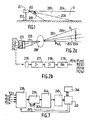
- Figure 1 shows schematically seen from the side the device according to the invention set up on a predetermined site.
- FIG. 2a illustrates a constructive arrangement making it possible to materialize the passive infrared detection technique according to the invention.
- Figure 2b is a block diagram of the first analog processing chain.
- Figure 3 shows the curve obtained for a tire vehicle.
- Figure 4 shows the curve obtained for a tracked vehicle.
- FIG. 5 illustrates how the opening of a detector is determined.
- FIG. 6 represents, in a view similar to that of FIG. 1, the case of several detectors for detection in a door in wide distance.
- Figure 7 is a block diagram of the second digital processing chain.
- FIG. 1 a detection and monitoring device according to the invention, 201.
- This device is installed, fixed, on a site 202, and comprises, as shown in FIG. 2a, an optical system making it possible to focus , on at least one detector, a narrow beam for detecting passive infrared radiation (IR-P).
- the detection beam 203 seen transversely, comes from a point 02 located approximately 1 m high; its elevation angle ⁇ s of the order of one to several tens of degrees is limited by a substantially horizontal straight line 204 and an oblique 205 directed downwards and the axis of symmetry 206 due beam 203 is an oblique which meets the ground between a few meters and a few tens of meters.
- the bearing angle ⁇ g is of the order of one to a few tenths of degrees.
- the beam 203 whose solid analysis angle is ⁇ s . ⁇ g consists, in the example of FIG. 2a, of n under contiguous beams in a vertical reference plane U gui comprises the axis 206 , opening in deposit: ⁇ g and opening in site ⁇ s / n , n being equal to 4 in the example chosen.
- Each detector of the network 209 is followed by an analog signal processing chain shown in FIG. 2b.
- This chain comprises in cascade the detector 216 which represents one of the detectors 211, 212, 213 or 214, a preamplifier 217, an amplifier 218 and a bandpass filter 219.
- the filter 219 supplies the voltage V216 (V211, V212, V213 or V214).
- the overall bandwidth of this processing chain is between a few tenths of Hz (typically 0.5 Hz), to be insensitive to the DC component, and a few tens of Hz (typically 50 Hz), which corresponds to the frequency of maximum modulation necessary to take into account vehicles likely to cross the reference plane U.
- the assembly constituted by the optical system 208, the filter 211, the detector 216 and its amplification and filtering chain has a temperature difference - noise equivalent (NETD) less than 1 ° K.
- NETD temperature difference - noise equivalent
- the purpose of the simplified infrared analysis carried out by the invention is to collect, day and night, a certain amount of information on one (or more) vehicle (s) having passed through the detection beam 203, either for the identify, whether or not to place it in the class of objectives to be destroyed in the context of a military application. In the latter case, this analysis comes after certain tests relating to the passing distance and the vehicle speed have been successfully passed.
- the tires 221, 222 are heated by friction and deformation. These tires (typically three in number for a truck) are rarely hidden because at the front (221) the wheels provide direction and the necessary lateral movement prevents them from being fully integrated behind the bodywork and at the rear (222), for reasons of ease of access, they are not covered with cover.
- the rocker panel consists of a number of rollers 223 generally greater than 6. On these rollers rub the tracks 224, which has the consequence of bringing their periphery to an apparent temperature sensitive. These rollers are provided with a long-travel suspension, so they are not entirely maskable by skirts.
- a kinematic inversion has been produced according to which the virtual image of the detector is supposed to move, in the direction of an arrow 226, between the ground 202 and a horizontal plane PH passing through. by line 204 ( Figure 1), along the lower part of the vehicle, the actual movement being opposite. This movement takes place on a linear scale.
- curves 227 and 228 The attributes exploitable from curves 227 and 228 are pulses (peaks) of sufficient amplitude to assimilate them to as many elements of the running gear. We can then count the number of pulses, their width, their spacing and establish a comparison with typical curves representative of this or that class of vehicles.
- the distance from the vehicle has no influence on the duration of crossing the reference plane U.
- the parameters which influence this duration are the speed of the vehicle and its angle of presentation ⁇ relative to the plane U.
- the distance plays on the other hand, a role as regards the definition of the bearing angle ⁇ g of the detection beam 203.
- n pyroelectric detectors will be used, for example 4 detectors giving birth to 4 under contiguous detection beams 233, 234, 235, 236 of elevation angle ⁇ s / 4 as shown in Figure 6.
- FIG. 7 is suitable for the case of several detectors in which the signals V211 to V214 are supplied to a multiplexer 238 followed by a sampler-blocker 329.
- the multiplexer 238 is intended to bring successively to a single coding channel the signals V unique to V214.
- the control signal on a conductor 241 of the multiplexer comes from a management processor 242 which supervises the operation of the entire device.
- the unique signal V216 is supplied directly to the sampler-blocker 239 which, under the control of a sampling signal at the frequency f EIR on a conductor 243 coming from the processor 242 , takes the analog value of the signal (or signals) V216.
- the digital processing chain of FIG. 7 further comprises an analog-digital converter 244 and a memory for storing the digital values of the samples, 245.
- the data processing circuit constituted by the processor 242 and its associated program memory 246 applies the digital filtering and algorithms for extracting the characteristic attributes of vehicles.
- the sampling period T EIR of the signals at 239 must be calculated such that it is lower than the duration of a pulse 229 on 231.
- T EIR can be determined from the minimum distance resolution rh which is wishes to have on the vehicle, whatever its angle of presentation ⁇ in a predetermined range of values and the value of the maximum apparent speed v max of the vehicle.
- the value of T EIR is therefore deduced from the relation: For a more complex detection system incorporating other sensors, it is possible to have available the distance D of the vehicle as well as its apparent angular speed d ⁇ / dt; in this case, it comes: This last calculation method makes it possible to ensure that the number of samples taken on a vehicle of fixed length is the same regardless of its passage distance.
- the management processor 242 is for example a microprocessor 6809 from the company Motorola and the algorithms necessary for its programming for the implementation of the invention are within the reach of those skilled in the art, in this case the average computer scientist .
- the optical part of the device can be produced in transmission by means of optical elements of germanium for example, or in reflection by means of a concave reflecting mirror constituted by a molded form of plastic material coated with a thin layer. metallic.
Landscapes
- Physics & Mathematics (AREA)
- General Physics & Mathematics (AREA)
- Geophysics And Detection Of Objects (AREA)
- Traffic Control Systems (AREA)
- Optical Radar Systems And Details Thereof (AREA)
Claims (5)
- Vorrichtung (201) zur Erfassung unberechtigten Eindringens und zur Erkennung von Bodenfahrzeugen, wenn diese eine Bezugsebene (U) durchqueren, mit einem optischen System (208) zur Fokussierung eines schmalen Strahls (203) zur Erfassung einer passiven Infrarotstrahlung entlang der Bezugsebene, einem die Auswahl des Analyse-Spektralbandes ermöglichenden Filter (210) und wenigstens einem in der Fokussierungsebene (209) des optischen Systems angeordneten Detektor, wobei jedem Detektor eine erste analoge Verarbeitungskette zur Signalverstärkung und -filterung folgt, außerdem mit einer zweiten digitalen Signalverarbeitungskette hinter der ersten Kette, die Mittel zur Signalabtastung und zur Speicherung der Abtastproben enthält, dadurch gekennzeichnet, daß die Verarbeitung der Abtastproben so ausgeführt wird, daß von den Signalverarbeitungsmitteln wenigstens das Fahrwerk der Fahrzeuge in Form einer zeitabhängigen Kurve, entlang der jedes sich drehende Element des Fahrwerks die Form eines identifizierbaren charakteristischen Impulses (229, 231) annimmt, nachgebildet wird.
- Vorrichtung zur Erfassung unberechtigten Eindringens und zur Erkennung gemäß Anspruch 1, dadurch gekennzeichnet, daß die Mittel zur Verarbeitung der Abtastproben von einem Mikroprozessor gebildet werden.
- Vorrichtung zur Erfassung unberechtigten Eindringens und zur Erkennung gemäß Anspruch 1 oder 2, dadurch gekennzeichnet, daß der vom Detektor und der ersten analogen Verarbeitungskette gebildete Aufbau eine Bandbreite zwischen einigen Zehntel Hertz und einigen zehn Hertz besitzt und daß der genannte Aufbau und das optische System eine Temperaturäquivalenz-Rauschdifferenz von weniger als 1°K besitzen.
- Vorrichtung zur Erfassung unberechtigten Eindringens und zur Erkennung gemäß einem der Ansprüche 1 bis 3, dadurch gekennzeichnet, daß bei dem vorgesehenen maximalen Beobachtungsabstand und für sämtliche erwarteten Darstellungswinkel der Fahrzeuge in bezug auf die Bezugsebene der Öffnungswinkel des Bündels der passiven Infrarotstrahlung derart ist, daß der Abstand zwischen zwei benachbarten sich drehenden Elementen des Fahrwerks (221, 222) von jedem Detektor aufgelöst wird.
- Vorrichtung zur Erfassung unberechtigten Eindringens und zur Erkennung in einem Abstandsfenster zwischen einigen Metern und einigen 10 Metern gemäß einem der Ansprüche 1 bis 4, dadurch gekennzeichnet, daß sie eine Mehrzahl von n pyroelektrischen Detektoren umfaßt, die in vertikaler Richtung angeordnet sind und aneinander angrenzen, derart, daß sie in der Bezugsebene n benachbarte Unter-Erfassungsbündel (233, 236) mit einem jeweiligen Zielhöhenwinkel Θs/n in der Größenordnung von einigen Grad definieren, wobei der Zielhöhenwinkel ⊖s des Bündels von einer Horizontalen der Bezugsebene, die sich in einer Höhe von ungefähr 1 m befindet, in Abwärtsrichtung gezählt wird.
Applications Claiming Priority (2)
| Application Number | Priority Date | Filing Date | Title |
|---|---|---|---|
| FR8618050 | 1986-12-23 | ||
| FR8618050A FR2608777B1 (fr) | 1986-12-23 | 1986-12-23 | Dispositif de detection d'intrusion et de reconnaissance de vehicules terrestres |
Publications (2)
| Publication Number | Publication Date |
|---|---|
| EP0276513A1 EP0276513A1 (de) | 1988-08-03 |
| EP0276513B1 true EP0276513B1 (de) | 1991-11-06 |
Family
ID=9342212
Family Applications (1)
| Application Number | Title | Priority Date | Filing Date |
|---|---|---|---|
| EP87202558A Expired - Lifetime EP0276513B1 (de) | 1986-12-23 | 1987-12-17 | Eindringdetektions- und Strassenfahrzeug-Identifizierungsvorrichtung |
Country Status (5)
| Country | Link |
|---|---|
| US (1) | US5012099A (de) |
| EP (1) | EP0276513B1 (de) |
| JP (1) | JP2567887B2 (de) |
| DE (1) | DE3774423D1 (de) |
| FR (1) | FR2608777B1 (de) |
Families Citing this family (15)
| Publication number | Priority date | Publication date | Assignee | Title |
|---|---|---|---|---|
| GB2249690B (en) * | 1990-11-07 | 1994-07-06 | Gec Ferranti Defence Syst | Security system |
| DE4040811A1 (de) * | 1990-12-14 | 1992-07-09 | Iris Gmbh Infrared & Intellige | Richtungsselektive zaehl- und schaltvorrichtung |
| US5283551A (en) * | 1991-12-31 | 1994-02-01 | Aritech Corporation | Intrusion alarm system |
| WO1995025322A1 (en) * | 1994-03-15 | 1995-09-21 | Gallium Software Inc. | Blind spot detector |
| GB2322442B (en) * | 1997-02-19 | 2000-12-06 | Agd Systems Ltd | A method of detecting the emission of infra-red radiation |
| US5886664A (en) * | 1997-04-16 | 1999-03-23 | Trw Inc. | Method and apparatus for detecting mines using radiometry |
| WO2003019494A1 (en) * | 2001-08-23 | 2003-03-06 | Qwip Technologies, Inc. | System and method for notification of hazardous road conditions |
| JP2004302699A (ja) * | 2003-03-28 | 2004-10-28 | Sumitomo Electric Ind Ltd | 車両検知器 |
| US7172450B1 (en) * | 2006-01-11 | 2007-02-06 | Qualitau, Inc. | High temperature open ended zero insertion force (ZIF) test socket |
| US20080012749A1 (en) * | 2006-07-17 | 2008-01-17 | Innovative American Technology, Inc. | Standoff radiation detection system |
| RU2353892C2 (ru) * | 2007-02-26 | 2009-04-27 | Владимир Анатольевич Клевакин | Способ определения принадлежности наземной техники к стороне-участнице военных действий |
| RU2404403C1 (ru) * | 2009-11-30 | 2010-11-20 | Открытое акционерное общество "Авангард" | Комплексный способ определения принадлежности наземной техники и военнослужащих к стороне - участнице военных действий |
| DE102010046586B4 (de) * | 2010-09-25 | 2012-10-04 | Rtb Gmbh & Co. Kg | Verkehrsstauerfassung |
| JP5911681B2 (ja) * | 2011-08-22 | 2016-04-27 | 株式会社東芝 | 移動回転体検出装置 |
| KR101927359B1 (ko) * | 2017-01-04 | 2018-12-11 | 주식회사 에스원 | 반사판 기반 레이더 감지기에서 차량 신호에 의한 오작동 방지 방법 및 이를 이용한 차량 신호에 의한 오작동 방지 시스템 |
Family Cites Families (15)
| Publication number | Priority date | Publication date | Assignee | Title |
|---|---|---|---|---|
| CA585176A (en) * | 1959-10-13 | N. Howell Sabert | Hot-box detector | |
| US3646343A (en) * | 1970-02-26 | 1972-02-29 | Gen Electric | Method and apparatus for monitoring hot boxes |
| JPS5093799A (de) * | 1973-12-21 | 1975-07-26 | ||
| GB1503762A (en) * | 1975-04-01 | 1978-03-15 | Elliott Bros | Surveillance systems |
| NL7606899A (nl) * | 1976-06-24 | 1977-12-28 | Optosche Ind De Oude Delft Nv | Opto-elektrisch detectiestelsel. |
| GB2129639B (en) * | 1979-10-19 | 1984-10-31 | France Etat | Detecting vehicles |
| US4300824A (en) * | 1979-11-15 | 1981-11-17 | Canon Inc. | Signal processing circuitry for a distance measuring system |
| US4348898A (en) * | 1980-02-11 | 1982-09-14 | The Goodyear Tire & Rubber Company | Direct reading temperature and circumferential tire monitor |
| US4323211A (en) * | 1980-04-28 | 1982-04-06 | Servo Corporation Of America | Self adjusting wheel bearing heat signal processing circuit |
| DE3119720C2 (de) * | 1981-05-18 | 1985-07-11 | Richard Hirschmann Radiotechnisches Werk, 7300 Esslingen | Auf elektromagnetische Strahlung ansprechender Bewegungsmelder |
| JPS5844999A (ja) * | 1981-09-10 | 1983-03-16 | Meinou Kikai Seisakusho:Kk | プレス機械のプレス騒音防止方法及びその装置 |
| BR8203508A (pt) * | 1981-10-05 | 1983-06-07 | Servo Corp Of America | Tema detector de caixa quente de carro de estrada de ferro |
| JPS59228136A (ja) * | 1983-06-10 | 1984-12-21 | King Tsushin Kogyo Kk | 受動型赤外線侵入検出装置 |
| DE3439068C1 (de) * | 1984-10-25 | 1986-01-09 | Messerschmitt-Bölkow-Blohm GmbH, 8012 Ottobrunn | Einrichtung zur optischen Erkennung beweglicher Ziele |
| JPS62121523U (de) * | 1986-01-24 | 1987-08-01 |
-
1986
- 1986-12-23 FR FR8618050A patent/FR2608777B1/fr not_active Expired
-
1987
- 1987-12-17 EP EP87202558A patent/EP0276513B1/de not_active Expired - Lifetime
- 1987-12-17 DE DE8787202558T patent/DE3774423D1/de not_active Expired - Fee Related
- 1987-12-21 JP JP62321598A patent/JP2567887B2/ja not_active Expired - Lifetime
-
1990
- 1990-05-01 US US07/519,351 patent/US5012099A/en not_active Expired - Fee Related
Also Published As
| Publication number | Publication date |
|---|---|
| DE3774423D1 (de) | 1991-12-12 |
| EP0276513A1 (de) | 1988-08-03 |
| US5012099A (en) | 1991-04-30 |
| FR2608777B1 (fr) | 1989-03-24 |
| JPS63172398A (ja) | 1988-07-16 |
| FR2608777A1 (fr) | 1988-06-24 |
| JP2567887B2 (ja) | 1996-12-25 |
Similar Documents
| Publication | Publication Date | Title |
|---|---|---|
| EP0276513A1 (de) | Eindringdetektions- und Strassenfahrzeug-Identifizierungsvorrichtung | |
| CA2859900C (fr) | Procede d'estimation de flot optique a partir d'un capteur asynchrone de lumiere | |
| JP7433265B2 (ja) | 表面における水を検出するための装置、および表面における水を検出するための方法 | |
| FR3035501A1 (de) | ||
| FR2822547A1 (fr) | Releve en trois dimensions de l'environnement, notamment d'un vehicule routier | |
| EP2232298A1 (de) | Ausrüstung zur erfassung von personen in einem abgegrenzten raum | |
| FR2940442A1 (fr) | Capteur et systeme d'imagerie pour la detection a distance d'un objet | |
| EP2994901B1 (de) | Kompakter detektor menschlicher präsenz | |
| EP3999820B1 (de) | Vorrichtung zur detektion von optischen impulsen | |
| EP1180758A1 (de) | Verfahren und Vorrichtung zur akustischer Detektion einer mobilen Schallquelle | |
| FR2684763A1 (fr) | Dispostif integre de detection et d'identification d'obstacles embarque notamment a bord d'un vehicule automobile. | |
| FR2953939A1 (fr) | Systeme radar uhf pour mettre en oeuvre un procede d'elimination d'un fouillis de vegetation | |
| EP3528224B1 (de) | Vorrichtung und verfahren zur präsenz- und/oder bewegungserkennung durch infrarot-messung | |
| FR2675610A1 (fr) | Procede et installation d'evaluation d'un flux de circulation de vehicules routiers. | |
| WO2009086928A1 (fr) | Procede, systeme et installation de detection pour garantir l'unicite de passage d'un objet | |
| EP0301947B1 (de) | Optoelektrisches Gerät zum Detektieren und zur Standortbestimmung einer Strahlungsquelle | |
| EP1105712B1 (de) | Messvorrichtung der grösse sich bewegender teilchen, insbesondere für regenmessungen | |
| EP0308324B1 (de) | Doppler-Sicherheits-Geschwindigkeitsmesseinrichtung | |
| WO2021148468A1 (fr) | Dispositif de detection de reliefs a la surface du sol pour dispositif roulant electrique et dispositif roulant electrique associe | |
| FR2612647A1 (fr) | Dispositif de modulation pour un dispositif detecteur de rayonnement captant un champ d'image | |
| FR2665954A1 (fr) | Procede de commande de mise a feu d'une mine, et mine pourvue d'un dispositif de declenchement fonctionnant selon ce procede. | |
| EP2985635B1 (de) | Schranke zur zugangskontrolle | |
| WO2025186526A1 (fr) | Dispositif de comptage automatique avec capteur thermique associe a un magnetometre | |
| FR2807843A1 (fr) | Perfectionnements a la detection de la presence d'une personne ou d'un animal dans un coffre de vehicule automobile | |
| FR2679682A1 (fr) | Procede pour detecter les changements de l'etat d'occupation d'une voie. |
Legal Events
| Date | Code | Title | Description |
|---|---|---|---|
| PUAI | Public reference made under article 153(3) epc to a published international application that has entered the european phase |
Free format text: ORIGINAL CODE: 0009012 |
|
| AK | Designated contracting states |
Kind code of ref document: A1 Designated state(s): DE FR GB IT SE |
|
| 17P | Request for examination filed |
Effective date: 19890123 |
|
| 17Q | First examination report despatched |
Effective date: 19901205 |
|
| GRAA | (expected) grant |
Free format text: ORIGINAL CODE: 0009210 |
|
| RAP1 | Party data changed (applicant data changed or rights of an application transferred) |
Owner name: THOMSON-TRT DEFENSE |
|
| AK | Designated contracting states |
Kind code of ref document: B1 Designated state(s): DE FR GB IT SE |
|
| ITF | It: translation for a ep patent filed | ||
| REF | Corresponds to: |
Ref document number: 3774423 Country of ref document: DE Date of ref document: 19911212 |
|
| GBT | Gb: translation of ep patent filed (gb section 77(6)(a)/1977) | ||
| PLBE | No opposition filed within time limit |
Free format text: ORIGINAL CODE: 0009261 |
|
| STAA | Information on the status of an ep patent application or granted ep patent |
Free format text: STATUS: NO OPPOSITION FILED WITHIN TIME LIMIT |
|
| 26N | No opposition filed | ||
| EAL | Se: european patent in force in sweden |
Ref document number: 87202558.0 |
|
| PGFP | Annual fee paid to national office [announced via postgrant information from national office to epo] |
Ref country code: GB Payment date: 19961119 Year of fee payment: 10 |
|
| PGFP | Annual fee paid to national office [announced via postgrant information from national office to epo] |
Ref country code: SE Payment date: 19961120 Year of fee payment: 10 |
|
| PG25 | Lapsed in a contracting state [announced via postgrant information from national office to epo] |
Ref country code: GB Free format text: LAPSE BECAUSE OF NON-PAYMENT OF DUE FEES Effective date: 19971217 |
|
| PG25 | Lapsed in a contracting state [announced via postgrant information from national office to epo] |
Ref country code: SE Free format text: LAPSE BECAUSE OF NON-PAYMENT OF DUE FEES Effective date: 19971218 |
|
| GBPC | Gb: european patent ceased through non-payment of renewal fee |
Effective date: 19971217 |
|
| EUG | Se: european patent has lapsed |
Ref document number: 87202558.0 |
|
| PGFP | Annual fee paid to national office [announced via postgrant information from national office to epo] |
Ref country code: FR Payment date: 20031210 Year of fee payment: 17 |
|
| PGFP | Annual fee paid to national office [announced via postgrant information from national office to epo] |
Ref country code: DE Payment date: 20031229 Year of fee payment: 17 |
|
| PG25 | Lapsed in a contracting state [announced via postgrant information from national office to epo] |
Ref country code: DE Free format text: LAPSE BECAUSE OF NON-PAYMENT OF DUE FEES Effective date: 20050701 |
|
| PG25 | Lapsed in a contracting state [announced via postgrant information from national office to epo] |
Ref country code: FR Free format text: LAPSE BECAUSE OF NON-PAYMENT OF DUE FEES Effective date: 20050831 |
|
| REG | Reference to a national code |
Ref country code: FR Ref legal event code: ST |
|
| PG25 | Lapsed in a contracting state [announced via postgrant information from national office to epo] |
Ref country code: IT Free format text: LAPSE BECAUSE OF NON-PAYMENT OF DUE FEES;WARNING: LAPSES OF ITALIAN PATENTS WITH EFFECTIVE DATE BEFORE 2007 MAY HAVE OCCURRED AT ANY TIME BEFORE 2007. THE CORRECT EFFECTIVE DATE MAY BE DIFFERENT FROM THE ONE RECORDED. Effective date: 20051217 |