EP0276724A2 - Outil carottier à entraînement direct - Google Patents
Outil carottier à entraînement direct Download PDFInfo
- Publication number
- EP0276724A2 EP0276724A2 EP88100667A EP88100667A EP0276724A2 EP 0276724 A2 EP0276724 A2 EP 0276724A2 EP 88100667 A EP88100667 A EP 88100667A EP 88100667 A EP88100667 A EP 88100667A EP 0276724 A2 EP0276724 A2 EP 0276724A2
- Authority
- EP
- European Patent Office
- Prior art keywords
- core drilling
- motor
- core
- outer tube
- axial feed
- Prior art date
- Legal status (The legal status is an assumption and is not a legal conclusion. Google has not performed a legal analysis and makes no representation as to the accuracy of the status listed.)
- Granted
Links
Images


Classifications
-
- E—FIXED CONSTRUCTIONS
- E21—EARTH OR ROCK DRILLING; MINING
- E21B—EARTH OR ROCK DRILLING; OBTAINING OIL, GAS, WATER, SOLUBLE OR MELTABLE MATERIALS OR A SLURRY OF MINERALS FROM WELLS
- E21B4/00—Drives for drilling, used in the borehole
- E21B4/02—Fluid rotary type drives
-
- E—FIXED CONSTRUCTIONS
- E21—EARTH OR ROCK DRILLING; MINING
- E21B—EARTH OR ROCK DRILLING; OBTAINING OIL, GAS, WATER, SOLUBLE OR MELTABLE MATERIALS OR A SLURRY OF MINERALS FROM WELLS
- E21B25/00—Apparatus for obtaining or removing undisturbed cores, e.g. core barrels or core extractors
- E21B25/02—Apparatus for obtaining or removing undisturbed cores, e.g. core barrels or core extractors the core receiver being insertable into, or removable from, the borehole without withdrawing the drilling pipe
- E21B25/04—Apparatus for obtaining or removing undisturbed cores, e.g. core barrels or core extractors the core receiver being insertable into, or removable from, the borehole without withdrawing the drilling pipe the core receiver having a core forming cutting edge or element, e.g. punch type core barrels
-
- E—FIXED CONSTRUCTIONS
- E21—EARTH OR ROCK DRILLING; MINING
- E21B—EARTH OR ROCK DRILLING; OBTAINING OIL, GAS, WATER, SOLUBLE OR MELTABLE MATERIALS OR A SLURRY OF MINERALS FROM WELLS
- E21B44/00—Automatic control systems specially adapted for drilling operations, i.e. self-operating systems which function to carry out or modify a drilling operation without intervention of a human operator, e.g. computer-controlled drilling systems; Systems specially adapted for monitoring a plurality of drilling variables or conditions
- E21B44/005—Below-ground automatic control systems
Definitions
- the invention relates to a directly driven core drilling tool according to the preamble of claim 1.
- Such tools can be used for core drilling work of all common deep drilling rigs.
- the entire drill string does not have to be removed to remove the core.
- a core drilling tool of the type mentioned at the outset which allows the core drilling device to be pulled with the outer tube remaining in the borehole, and in which the core drilling device is axially displaceable in the outer tube during the core.
- the motor of this tool remains in the core
- the outer tube is axially secured and is rotatably coupled to the displaceable core drilling device via displaceable coupling members.
- the core drilling device provides the rinsing liquid with reaction surfaces which, as a result of the drilling fluid pressure above it and in connection with the expansion of the surfaces, impart an axial feed force to it.
- the drilling fluid pressure above the core drilling device is caused by the throttling action of the annular spaces and gaps in the core drilling device on the drilling fluid flowing through.
- a first flow-through space is formed between a core tube and an inner tube carrying a drill bit.
- a second flow-through space is located between the inner tube mentioned and a jacket tube surrounding it. While the throttling effect of the first room remains constant, the throttling effect of the second room decreases with increasing exposure of the core drilling device from the casing tube.
- the drilling fluid pressure and thus the axial feed force are proportional to the sum of the throttling effects of both rooms.
- the maximum value of the axial feed force is relatively low and the force cannot be influenced in terms of its size.
- the object on which the invention is based is to improve a directly driven core drilling tool in such a way that a sufficiently large axial feed force, which is essentially independent of the exposure of the core drilling device and can be selected in terms of its size, can be impressed on the core drilling device.
- the considerably higher drilling fluid pressure present above the motor can also be used to generate an axial feed force. Since this pressure is independent of the exposure of the core drilling device, the exposure-dependent influences on the total drilling fluid pressure above the unit are reduced.
- the means for adjusting the axial feed force can also be used for other working conditions, e.g. a different mud weight or a different drill bit can be adjusted. The invention thus enables the tool to be used universally without inadvertently overloading the motor and consequently achieves optimum drilling progress.
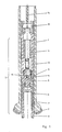
- the core drilling tool shown in Fig. 1 has an outer tube 1 which can be connected to a drill string, not shown. At the lower end, a roller core bit 2 is attached, which is used for drilling out an annular space and repositioning the outer tube 1 when the exposure area of the core tube is exhausted.
- a unit 3 comprising a motor 4 and a core drilling device 5 is located within the outer tube 1. This unit 3 is axially displaceable. While the motor 4 is secured against rotating, the core drilling device 5 is rotatably arranged.
- the core drilling device 5 itself consists of a core tube 7 carrying a drill bit 6 and an inner tube 8 rotatably supported therein.
- a drilling fluid distributor 9 is arranged between the motor 4 and the core drilling device 5 and divides the drilling fluid emerging from the motor 4 into a first stream, which flows between the outer tube 1 and the core tube 7 and in a further stream between the core tube 7 and the inner tube 8.
- the stream flowing between the outer tube 1 and the core tube 7 is controlled by a spring-loaded valve 10 so that it despite decreasing throttling effect of the flow path due to increasing exposure of the core drilling device 5 remains the same.
- the motor 4 is provided with a collar 11 which fills the annular space between its housing and the outer tube 1.
- the collar 11 is sealed off from the outer tube 1 and, with further housing areas of the motor 4, forms partial areas which fill the cross-sectional area of an inner passage area 12 of the outer tube 1. These partial areas result in the reaction areas of the drilling fluid pressure present above the unit 3 and generate the axial feed force for the unit 3.
- a catching device 13 which serves to pull up the entire unit 3 after drilling a core.
- the catching device 13 serves in the first embodiment according to the invention as a means for adjusting the axial feed force by opposing the core drilling device 5 with a retaining force which is fed to it via a cable 14 leading through the drill string by means of a winch located on the drilling tower.
- values between a maximum value and zero can be set for the resulting axial feed force. The maximum value results when the axial feed force is determined in full by the drilling fluid pressure present above the unit 3 in connection with the reaction surfaces.
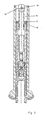
- the pressurized reaction surfaces are designed as a cross-sectional surface of a flushing mandrel 15 connected to the motor.
- the mandrel provided for the catching device 13 is used for this purpose, but it is hollow on the inside and has inlet openings 16.
- the means for adjusting the axial feed force comprise a sleeve 17 which is supported and sealed in the outer tube 1, has an opening 18 and is penetrated by the flushing pin 15.
- the flushing pin 15 is sealed against the sleeve 17.
- the axial feed force is adjusted by selecting and preassembling a sleeve 17 with a specific cross section of the opening 18 and a mandrel 15 matched to it before the unit 3 is let into the outer tube 1.
- the flushing mandrel 15 carries a piston 19 which has the cross-sectional area of a further passage area 20 and contains nozzles 21.
- the inlet openings 22 of the flushing mandrel 15 are located below the piston 19 in the form of radial slots.
- the piston 19 creates an additional portion of the axial feed force by making use of the differential pressure present across the nozzles 21. This differential pressure acts on the cross-sectional area of the inner passage area 20 of the outer tube 1 occupied by the piston 19 minus the nozzle cross section.
- the additional portion of the axial feed force can be adjusted by the selection of the nozzles 21 and the volume flow of the drilling fluid.
- the advantage of this embodiment is that a set of nozzles 21 of different sizes is less complex than such a differently sized flushing mandrel 15 and sleeves 17, as required by the embodiment of FIG. 2, and the time required for replacement is less.
- valve 23 which is controlled by the return torque of the motor 4.
- This valve 23 consists in detail of a fixed valve seat 24 and a valve body 26 which is coupled to the motor housing and can be pivoted to a limited extent against a torque spring 25.
- the reaction surfaces for the axial feed force are again the same partial surfaces as those mentioned in the embodiment according to FIG. 1.
- the drilling fluid pressure can then no longer propagate to the full extent or not at all in the region of the collar 11 and is only present on partial areas of the motor housing that are small in cross section. This causes a ver reduction of the axial feed force.
- In stationary operation there will be an angular position between the valve body 26 and the valve seat 24, in which the torque of the drill bit 6 and the associated axial feed force assume an equilibrium state.
- the third modification of the invention thus offers an independent setting possibility even within a large volume flow and pressure range of the drilling fluid.
Landscapes
- Engineering & Computer Science (AREA)
- Life Sciences & Earth Sciences (AREA)
- Geology (AREA)
- Mining & Mineral Resources (AREA)
- Physics & Mathematics (AREA)
- Environmental & Geological Engineering (AREA)
- Fluid Mechanics (AREA)
- General Life Sciences & Earth Sciences (AREA)
- Geochemistry & Mineralogy (AREA)
- Mechanical Engineering (AREA)
- Earth Drilling (AREA)
- Processing Of Stones Or Stones Resemblance Materials (AREA)
Applications Claiming Priority (2)
| Application Number | Priority Date | Filing Date | Title |
|---|---|---|---|
| DE3701914 | 1987-01-23 | ||
| DE3701914A DE3701914C1 (de) | 1987-01-23 | 1987-01-23 | Direktangetriebenes Kernbohrwerkzeug |
Publications (3)
| Publication Number | Publication Date |
|---|---|
| EP0276724A2 true EP0276724A2 (fr) | 1988-08-03 |
| EP0276724A3 EP0276724A3 (en) | 1990-08-22 |
| EP0276724B1 EP0276724B1 (fr) | 1994-09-21 |
Family
ID=6319376
Family Applications (1)
| Application Number | Title | Priority Date | Filing Date |
|---|---|---|---|
| EP88100667A Expired - Lifetime EP0276724B1 (fr) | 1987-01-23 | 1988-01-19 | Outil carottier à entraînement direct |
Country Status (4)
| Country | Link |
|---|---|
| US (1) | US4875531A (fr) |
| EP (1) | EP0276724B1 (fr) |
| CA (1) | CA1296319C (fr) |
| DE (1) | DE3701914C1 (fr) |
Cited By (3)
| Publication number | Priority date | Publication date | Assignee | Title |
|---|---|---|---|---|
| EP0380909A3 (fr) * | 1989-02-01 | 1992-03-11 | Eastman Teleco Company | Procédé et outil de carottage pour le forage de formations rocheuses souterraines |
| FR2675197A1 (fr) * | 1991-04-12 | 1992-10-16 | Leroy Andre | Appareil de forage petrolier, gazier ou geothermique. |
| US6644424B1 (en) | 1999-03-15 | 2003-11-11 | Halliburton Energy Services, Inc. | Core barrel |
Families Citing this family (27)
| Publication number | Priority date | Publication date | Assignee | Title |
|---|---|---|---|---|
| DE3825225A1 (de) * | 1988-07-25 | 1990-02-01 | Eastman Christensen Co | Bohrwerkzeug |
| DE3902870A1 (de) * | 1988-07-25 | 1990-02-01 | Eastman Christensen Co | Verfahren zum abteufen von bohrungen in unterirdische gesteinsformationen |
| DE3912067C1 (fr) * | 1989-04-13 | 1990-09-06 | Eastman Christensen Co., Salt Lake City, Utah, Us | |
| US5007490A (en) * | 1990-06-20 | 1991-04-16 | Ide Russell D | Progressive cavity drive train with elastomeric joint assembly for use in downhole drilling |
| US5135059A (en) * | 1990-11-19 | 1992-08-04 | Teleco Oilfield Services, Inc. | Borehole drilling motor with flexible shaft coupling |
| US5186265A (en) * | 1991-08-22 | 1993-02-16 | Atlantic Richfield Company | Retrievable bit and eccentric reamer assembly |
| US5168942A (en) * | 1991-10-21 | 1992-12-08 | Atlantic Richfield Company | Resistivity measurement system for drilling with casing |
| US6095259A (en) * | 1998-04-03 | 2000-08-01 | Keyes; Robert C. | Core sampler apparatus with specific attachment means |
| US8360174B2 (en) | 2006-03-23 | 2013-01-29 | Schlumberger Technology Corporation | Lead the bit rotary steerable tool |
| US8225883B2 (en) | 2005-11-21 | 2012-07-24 | Schlumberger Technology Corporation | Downhole percussive tool with alternating pressure differentials |
| US8522897B2 (en) | 2005-11-21 | 2013-09-03 | Schlumberger Technology Corporation | Lead the bit rotary steerable tool |
| US7571780B2 (en) | 2006-03-24 | 2009-08-11 | Hall David R | Jack element for a drill bit |
| US7753144B2 (en) | 2005-11-21 | 2010-07-13 | Schlumberger Technology Corporation | Drill bit with a retained jack element |
| US7497279B2 (en) * | 2005-11-21 | 2009-03-03 | Hall David R | Jack element adapted to rotate independent of a drill bit |
| US8297378B2 (en) | 2005-11-21 | 2012-10-30 | Schlumberger Technology Corporation | Turbine driven hammer that oscillates at a constant frequency |
| US7954401B2 (en) | 2006-10-27 | 2011-06-07 | Schlumberger Technology Corporation | Method of assembling a drill bit with a jack element |
| MX338284B (es) * | 2006-12-15 | 2016-04-11 | Schlumberger Technology Corp | Sistema para direccionamiento de una sarta de perforacion. |
| US7721826B2 (en) | 2007-09-06 | 2010-05-25 | Schlumberger Technology Corporation | Downhole jack assembly sensor |
| US8701799B2 (en) | 2009-04-29 | 2014-04-22 | Schlumberger Technology Corporation | Drill bit cutter pocket restitution |
| SI22761A (sl) * | 2009-07-22 | 2009-10-31 | Kmetijski inštitut Slovenije | Naprava za jemanje strukturno neporušenih vzorcev tal |
| US8739899B2 (en) * | 2010-07-19 | 2014-06-03 | Baker Hughes Incorporated | Small core generation and analysis at-bit as LWD tool |
| CN102619484B (zh) * | 2012-04-11 | 2014-09-10 | 中国石油集团川庆钻探工程有限公司钻采工程技术研究院 | 随钻井壁取心工具 |
| CN103015931B (zh) * | 2012-12-27 | 2015-08-19 | 中国石油集团川庆钻探工程有限公司 | 随钻取心的取心系统 |
| CN103015932B (zh) * | 2012-12-27 | 2015-08-19 | 中国石油集团川庆钻探工程有限公司 | 随钻取心的钻进系统 |
| CN104453765B (zh) * | 2013-09-24 | 2017-03-15 | 金川集团股份有限公司 | 绳索取芯钻具的打捞器 |
| CN110984878B (zh) * | 2019-11-08 | 2021-09-10 | 长江岩土工程有限公司 | 一种城市深埋隧道勘察孔绳索取芯钻进装置 |
| CN113175307B (zh) * | 2021-04-29 | 2022-04-15 | 四川大学 | 一种旋转密封提芯机构 |
Family Cites Families (6)
| Publication number | Priority date | Publication date | Assignee | Title |
|---|---|---|---|---|
| US2326435A (en) * | 1940-05-24 | 1943-08-10 | Pink T Bynum | Coring apparatus |
| US2898086A (en) * | 1954-12-02 | 1959-08-04 | Jersey Prod Res Co | Method of drilling |
| US2915285A (en) * | 1956-05-23 | 1959-12-01 | Jersey Prod Res Co | Coring subterranean formations |
| US4518051A (en) * | 1983-06-30 | 1985-05-21 | Chevron Research Company | Percussion actuated core sampler |
| US4518050A (en) * | 1983-06-30 | 1985-05-21 | Chevron Research Company | Rotating double barrel core sampler |
| US4721172A (en) * | 1985-11-22 | 1988-01-26 | Amoco Corporation | Apparatus for controlling the force applied to a drill bit while drilling |
-
1987
- 1987-01-23 DE DE3701914A patent/DE3701914C1/de not_active Expired
-
1988
- 1988-01-19 EP EP88100667A patent/EP0276724B1/fr not_active Expired - Lifetime
- 1988-01-22 CA CA000557188A patent/CA1296319C/fr not_active Expired - Lifetime
- 1988-01-25 US US07/148,676 patent/US4875531A/en not_active Expired - Fee Related
Cited By (4)
| Publication number | Priority date | Publication date | Assignee | Title |
|---|---|---|---|---|
| EP0380909A3 (fr) * | 1989-02-01 | 1992-03-11 | Eastman Teleco Company | Procédé et outil de carottage pour le forage de formations rocheuses souterraines |
| FR2675197A1 (fr) * | 1991-04-12 | 1992-10-16 | Leroy Andre | Appareil de forage petrolier, gazier ou geothermique. |
| WO1992018740A1 (fr) * | 1991-04-12 | 1992-10-29 | Leroy Andre | Appareil de forage petrolier, gazier ou geothermique |
| US6644424B1 (en) | 1999-03-15 | 2003-11-11 | Halliburton Energy Services, Inc. | Core barrel |
Also Published As
| Publication number | Publication date |
|---|---|
| EP0276724B1 (fr) | 1994-09-21 |
| DE3701914C1 (de) | 1988-05-19 |
| CA1296319C (fr) | 1992-02-25 |
| EP0276724A3 (en) | 1990-08-22 |
| US4875531A (en) | 1989-10-24 |
Similar Documents
| Publication | Publication Date | Title |
|---|---|---|
| EP0276724B1 (fr) | Outil carottier à entraînement direct | |
| DE2930014C2 (fr) | ||
| DE69314327T2 (de) | Bohrlochwerkzeug zum steuern der bohrrichtung eines bohrloches | |
| DE69527591T2 (de) | Motoranordnung zum Richtungsbohren | |
| DE60305733T2 (de) | Bohren eines bohrlochs | |
| DE3323332C2 (fr) | ||
| DE69411383T2 (de) | Hydraulischer bohrlochschlagschieber mit wartezeitreduzierung | |
| DE1533576B1 (de) | Einrichtung zum Einzementieren eines Futterrohrstranges in einem Bohrloch | |
| DE3113749C2 (de) | Vorrichtung zur Fernübertragung von Informationen aus einem Bohrloch zur Erdoberfläche während des Betriebs eines Bohrgerätes | |
| DE3104058A1 (de) | Hydraulisches schildvortriebs-tunnelbauverfahren sowie schildvortriebs-tunnelbaumaschine | |
| DE2919007A1 (de) | Bohrgeraet zum bohren eines kerns in tiefbohrloechern | |
| EP0352427B1 (fr) | Dispositif de forage | |
| DE68906043T2 (de) | Hydraulisches setzgeraet. | |
| DE2418392B2 (de) | Kern- und Vollbohrvorrichtung für den Einsatz mit Tieflochturbinen | |
| DE2423346C2 (de) | Verfahren und Vorrichtung zur Minderung des Verschleisses in der Axialbohrung eines Unterwasser-Bohrlochkopfes | |
| DE69008223T2 (de) | Einrichtung in Schlagmaschinen. | |
| AT390303B (de) | Bohrvorrichtung | |
| DE69634399T2 (de) | Zirkulationsstück | |
| DE2933678A1 (de) | Vorrichtung zum umkehren der zirkulationsrichtung eines ein bohrwerkzeug speisenden druckfluids | |
| DE69306456T2 (de) | Gesteinbohreinrichtung | |
| EP0469317A2 (fr) | Procédé et dispositif pour modifier le poids sur un outil de forage du sol | |
| DE3024102A1 (de) | Exzenter-bohrvorrichtung | |
| DE3343565C2 (de) | Tieflochhammer | |
| DE2953873C2 (de) | Kernbohreinrichtung für Gesteinsbohrlöcher | |
| DE3228106A1 (de) | Vorrichtung fuer das erdbohren mit hilfe des lufthebeverfahrens |
Legal Events
| Date | Code | Title | Description |
|---|---|---|---|
| PUAI | Public reference made under article 153(3) epc to a published international application that has entered the european phase |
Free format text: ORIGINAL CODE: 0009012 |
|
| AK | Designated contracting states |
Kind code of ref document: A2 Designated state(s): BE FR GB NL |
|
| PUAL | Search report despatched |
Free format text: ORIGINAL CODE: 0009013 |
|
| AK | Designated contracting states |
Kind code of ref document: A3 Designated state(s): BE FR GB NL |
|
| 17P | Request for examination filed |
Effective date: 19901208 |
|
| 17Q | First examination report despatched |
Effective date: 19920710 |
|
| RAP1 | Party data changed (applicant data changed or rights of an application transferred) |
Owner name: EASTMAN TELECO COMPANY |
|
| GRAA | (expected) grant |
Free format text: ORIGINAL CODE: 0009210 |
|
| AK | Designated contracting states |
Kind code of ref document: B1 Designated state(s): BE FR GB NL |
|
| ET | Fr: translation filed | ||
| GBT | Gb: translation of ep patent filed (gb section 77(6)(a)/1977) |
Effective date: 19941027 |
|
| PGFP | Annual fee paid to national office [announced via postgrant information from national office to epo] |
Ref country code: FR Payment date: 19941214 Year of fee payment: 8 |
|
| PGFP | Annual fee paid to national office [announced via postgrant information from national office to epo] |
Ref country code: BE Payment date: 19941222 Year of fee payment: 8 |
|
| PGFP | Annual fee paid to national office [announced via postgrant information from national office to epo] |
Ref country code: GB Payment date: 19941228 Year of fee payment: 8 |
|
| PGFP | Annual fee paid to national office [announced via postgrant information from national office to epo] |
Ref country code: NL Payment date: 19950131 Year of fee payment: 8 |
|
| PLBE | No opposition filed within time limit |
Free format text: ORIGINAL CODE: 0009261 |
|
| STAA | Information on the status of an ep patent application or granted ep patent |
Free format text: STATUS: NO OPPOSITION FILED WITHIN TIME LIMIT |
|
| 26N | No opposition filed | ||
| PG25 | Lapsed in a contracting state [announced via postgrant information from national office to epo] |
Ref country code: GB Effective date: 19960119 |
|
| PG25 | Lapsed in a contracting state [announced via postgrant information from national office to epo] |
Ref country code: BE Effective date: 19960131 |
|
| BERE | Be: lapsed |
Owner name: EASTMAN TELECO CY Effective date: 19960131 |
|
| PG25 | Lapsed in a contracting state [announced via postgrant information from national office to epo] |
Ref country code: NL Effective date: 19960801 |
|
| GBPC | Gb: european patent ceased through non-payment of renewal fee |
Effective date: 19960119 |
|
| PG25 | Lapsed in a contracting state [announced via postgrant information from national office to epo] |
Ref country code: FR Effective date: 19960930 |
|
| NLV4 | Nl: lapsed or anulled due to non-payment of the annual fee |
Effective date: 19960801 |
|
| REG | Reference to a national code |
Ref country code: FR Ref legal event code: ST |