EP0276758A2 - Barrage antiretour pour les agrégats de plastification et d'injection de machines à injecter - Google Patents
Barrage antiretour pour les agrégats de plastification et d'injection de machines à injecter Download PDFInfo
- Publication number
- EP0276758A2 EP0276758A2 EP88100864A EP88100864A EP0276758A2 EP 0276758 A2 EP0276758 A2 EP 0276758A2 EP 88100864 A EP88100864 A EP 88100864A EP 88100864 A EP88100864 A EP 88100864A EP 0276758 A2 EP0276758 A2 EP 0276758A2
- Authority
- EP
- European Patent Office
- Prior art keywords
- injection
- return valve
- plasticizing
- screw tip
- screw
- Prior art date
- Legal status (The legal status is an assumption and is not a legal conclusion. Google has not performed a legal analysis and makes no representation as to the accuracy of the status listed.)
- Withdrawn
Links
- 238000002347 injection Methods 0.000 title claims abstract description 42
- 239000007924 injection Substances 0.000 title claims abstract description 42
- 238000001746 injection moulding Methods 0.000 title claims abstract description 8
- 239000000463 material Substances 0.000 claims abstract description 17
- 229910010293 ceramic material Inorganic materials 0.000 claims abstract description 13
- 125000006850 spacer group Chemical group 0.000 claims abstract description 11
- 239000004033 plastic Substances 0.000 claims abstract description 9
- 229920003023 plastic Polymers 0.000 claims abstract description 9
- 239000000945 filler Substances 0.000 claims abstract description 5
- 239000012815 thermoplastic material Substances 0.000 claims abstract description 4
- 230000000295 complement effect Effects 0.000 claims abstract description 3
- RVTZCBVAJQQJTK-UHFFFAOYSA-N oxygen(2-);zirconium(4+) Chemical compound [O-2].[O-2].[Zr+4] RVTZCBVAJQQJTK-UHFFFAOYSA-N 0.000 claims description 3
- 229910001928 zirconium oxide Inorganic materials 0.000 claims description 3
- 239000004014 plasticizer Substances 0.000 claims 1
- 239000000919 ceramic Substances 0.000 description 5
- 229910000831 Steel Inorganic materials 0.000 description 4
- 229910045601 alloy Inorganic materials 0.000 description 4
- 239000000956 alloy Substances 0.000 description 4
- 239000010959 steel Substances 0.000 description 4
- 238000005299 abrasion Methods 0.000 description 3
- 230000000694 effects Effects 0.000 description 2
- 239000003365 glass fiber Substances 0.000 description 2
- 238000004519 manufacturing process Methods 0.000 description 2
- 239000000203 mixture Substances 0.000 description 2
- 229910052574 oxide ceramic Inorganic materials 0.000 description 2
- 239000011224 oxide ceramic Substances 0.000 description 2
- 229910000851 Alloy steel Inorganic materials 0.000 description 1
- 230000000903 blocking effect Effects 0.000 description 1
- 230000010006 flight Effects 0.000 description 1
- 239000008187 granular material Substances 0.000 description 1
- 229910001092 metal group alloy Inorganic materials 0.000 description 1
- 238000000465 moulding Methods 0.000 description 1
- 229910052573 porcelain Inorganic materials 0.000 description 1
- 239000007921 spray Substances 0.000 description 1
- 229920001169 thermoplastic Polymers 0.000 description 1
- 229920001187 thermosetting polymer Polymers 0.000 description 1
- 239000004416 thermosoftening plastic Substances 0.000 description 1
Images
Classifications
-
- B—PERFORMING OPERATIONS; TRANSPORTING
- B29—WORKING OF PLASTICS; WORKING OF SUBSTANCES IN A PLASTIC STATE IN GENERAL
- B29C—SHAPING OR JOINING OF PLASTICS; SHAPING OF MATERIAL IN A PLASTIC STATE, NOT OTHERWISE PROVIDED FOR; AFTER-TREATMENT OF THE SHAPED PRODUCTS, e.g. REPAIRING
- B29C45/00—Injection moulding, i.e. forcing the required volume of moulding material through a nozzle into a closed mould; Apparatus therefor
- B29C45/17—Component parts, details or accessories; Auxiliary operations
- B29C45/46—Means for plasticising or homogenising the moulding material or forcing it into the mould
- B29C45/58—Details
- B29C45/62—Barrels or cylinders
-
- B—PERFORMING OPERATIONS; TRANSPORTING
- B29—WORKING OF PLASTICS; WORKING OF SUBSTANCES IN A PLASTIC STATE IN GENERAL
- B29C—SHAPING OR JOINING OF PLASTICS; SHAPING OF MATERIAL IN A PLASTIC STATE, NOT OTHERWISE PROVIDED FOR; AFTER-TREATMENT OF THE SHAPED PRODUCTS, e.g. REPAIRING
- B29C45/00—Injection moulding, i.e. forcing the required volume of moulding material through a nozzle into a closed mould; Apparatus therefor
- B29C45/17—Component parts, details or accessories; Auxiliary operations
- B29C45/46—Means for plasticising or homogenising the moulding material or forcing it into the mould
- B29C45/47—Means for plasticising or homogenising the moulding material or forcing it into the mould using screws
- B29C45/50—Axially movable screw
- B29C45/52—Non-return devices
- B29C2045/526—Abrasion resistant means in the screw head or non-return device
Definitions
- the invention relates to a non-return valve for the plasticizing and injection units for injection molding machines, in particular for processing thermoplastic material with fillers, the non-return valve having a screw tip and an axially displaceable locking ring on the shaft of the screw tip, which against the spacer ring on the end face during the injection phase the plasticizing and injection screw is present and, during the plasticizing phase with the body of the screw tip, delimits through channels for the plasticized plastic material entering the plasticizing space.
- Injection molding machines are used to manufacture injection molded parts from thermoplastic, thermosetting or crosslinked plastics, these plastics being able to have an addition of glass fibers and the like, generally fillers.
- Injection molding machines are also used in the manufacture of ceramic moldings from unfired ceramic masses, such as unfired porcelain mass.
- the material to be processed is understood to mean both plastic material and unfired ceramic masses.
- the plastic material When processing plastic material, the plastic material is in principle granulated via an addition funnel Plasticizing and injection cylinder of the plasticizing and injection unit of the injection molding machine in question, wherein the plasticizing and injection screw is arranged axially displaceably in the plasticizing cylinder.
- the material to be processed is plasticized by the rotating screw and transported into the plasticizing space, which forms in front of the screw tip, from which the plasticized material is injected into the closed injection mold.
- injection pressure phase the plasticized material being injected through the sprue hole into the nest of the closed injection mold. Injection takes place in the injection pressure phase under the injection pressure.
- the injection phase is followed by the post-pressure phase, in which thermodynamic laws cool the mass in the nest under the pressure referred to as post-pressure and the shrinkage that occurs is compensated for by additional plasticized material.
- the back pressure phase is followed by the dynamic pressure phase, during which, as described at the beginning, the screw granulates plastic material and moves it away from the sprue bore in the opposite direction to the injection mold.
- the injection pressure phase, the holding pressure phase and the dynamic pressure phase each form a spray cycle, in the course of which an injection molded part or, using a multiple mold, several injection molded parts are produced simultaneously.
- the back pressure phase is eliminated when processing unfired ceramic masses.
- thermoplastic material fillers such as Glass fibers
- considerable wear occurs on the plasticizing and injection units. This applies in particular to the area of the non-return valve.
- both the injection cylinder and the screw and possibly the locking ring have so far been selected from metal alloys or steel alloys and other special steels. So far, these improvements have only been able to reduce the expected wear somewhat in the area of the non-return valve, but have not led to any notable successes, e.g. for the plasticizing cylinders or plasticizing and injection screws in the area of the screw flights.
- oxide ceramic material instead of such alloys, which comparatively reduces abrasion, such as extremely expensive special steels or special alloys (Brochure from Feldmühle, SPK oxide CERAMICS).
- the invention is therefore based on the object to provide a non-return valve of the type mentioned, in which the abrasion is extremely low, i.e. the service life is much longer than usual.
- the locking ring has an insert made of ceramic material in its contact area on the body of the screw tip and in the complementary contact area for the spacer ring.
- the spacer ring is a body made of ceramic material.
- the plasticizing cylinder has a sleeve made of ceramic material in the area of the non-return valve, so that generally the previously extremely high abrasion in this area of the non-return valve on the wall of the injection cylinder is considerably and unexpectedly reduced.
- compositions his trade names, can be found in the prospectus mentioned above.
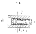
- Fig. 1 shows a section of a section of a plasticizing and injection unit in the cutout in the area of the non-return valve.
- 1 is the plasticizing and injection cylinder
- 2 is the plasticizing and injection screw, also shown in the detail, which has the non-return valve 3 in the direction of the injection mold (not shown) (see direction of arrow A).
- the non-return valve consists of the screw tip 4, the body 5 of the screw tip and the shaft 6 of the screw tip, which is screwed into the end face of the screw 2 (not shown).
- the spacer ring is arranged on the shaft 6 and is in an annular shape Area against the end face of the screw 2.
- the blocking ring 8 is arranged on the shaft 6 of the non-return valve, forming an annular gap.
- the locking ring 8 has an insert 9 in its contact area on the body 5 of the screw tip, which insert delimits the passage channels for the plasticized material entering the plasticizing space during the dynamic pressure phase with the body of the screw tip.
- the locking ring furthermore has an insert 10 made of ceramic material, which during the injection phase against the spacer ring 7 is present and prevents backflow into the area of the threads of the plasticizing and injection screw during the injection phase (closed position)
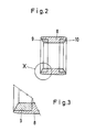
- FIG. 3 shows the detail X from FIG. 2 in an enlarged representation.
- the plasticizing and injection cylinder has a sleeve 11 made of ceramic material in the area of the non-return valve.
Landscapes
- Engineering & Computer Science (AREA)
- Manufacturing & Machinery (AREA)
- Mechanical Engineering (AREA)
- Injection Moulding Of Plastics Or The Like (AREA)
Applications Claiming Priority (2)
| Application Number | Priority Date | Filing Date | Title |
|---|---|---|---|
| DE3702191 | 1987-01-26 | ||
| DE19873702191 DE3702191A1 (de) | 1987-01-26 | 1987-01-26 | Rueckstroemsperre fuer die plastifizier- und spritzaggregate fuer spritzgiessmaschinen |
Publications (2)
| Publication Number | Publication Date |
|---|---|
| EP0276758A2 true EP0276758A2 (fr) | 1988-08-03 |
| EP0276758A3 EP0276758A3 (fr) | 1990-02-14 |
Family
ID=6319543
Family Applications (1)
| Application Number | Title | Priority Date | Filing Date |
|---|---|---|---|
| EP88100864A Withdrawn EP0276758A3 (fr) | 1987-01-26 | 1988-01-21 | Barrage antiretour pour les agrégats de plastification et d'injection de machines à injecter |
Country Status (3)
| Country | Link |
|---|---|
| EP (1) | EP0276758A3 (fr) |
| AU (1) | AU1078888A (fr) |
| DE (1) | DE3702191A1 (fr) |
Cited By (2)
| Publication number | Priority date | Publication date | Assignee | Title |
|---|---|---|---|---|
| EP1226920A1 (fr) * | 2001-01-30 | 2002-07-31 | Karl Hehl | Procédé pour la fabrication d'une soupape annulaire pour le barrage antireflex d'une machine de moulage par injection ainsi que le clapet antiretour correspondant |
| DE10103863C1 (de) * | 2001-01-30 | 2002-08-08 | Karl Hehl | Verfahren zur Herstellung eines Führungselements einer Rückstromsperre sowie entsprechendes Führungselement |
Families Citing this family (5)
| Publication number | Priority date | Publication date | Assignee | Title |
|---|---|---|---|---|
| DE3717735C1 (en) * | 1987-05-26 | 1988-02-18 | Krauss Maffei Ag | Non-return valve for a plastication screw |
| AU5856090A (en) * | 1989-07-07 | 1991-02-06 | Endorecherche Inc. | Androgen derivatives for use in the inhibition of sex steroid activity |
| DE4012933A1 (de) * | 1990-04-24 | 1991-10-31 | Bosch Gmbh Robert | Maschinen- und werkzeugteile fuer spritzgiessen, extrudieren, strangpressen und druckguss |
| DE4419405C2 (de) * | 1994-06-03 | 1996-11-21 | Kloeckner Desma Elastomertechn | Plastifizier- und Spritzeinheit für Spritzgießmaschinen zur Erzeugung von Gummi- oder Kunststoffartikeln |
| DE10217758B4 (de) * | 2002-04-20 | 2005-06-16 | Krauss-Maffei Kunststofftechnik Gmbh | Rückstromsperre für Spritzgießmaschine |
Family Cites Families (3)
| Publication number | Priority date | Publication date | Assignee | Title |
|---|---|---|---|---|
| FR2112691A5 (en) * | 1970-11-06 | 1972-06-23 | Deutsch Co | Injection moulding check valve - with low wastage, losses etc |
| GB1335824A (en) * | 1970-11-26 | 1973-10-31 | Strode Components Ltd | Injection moulding feed screw |
| DE3437559A1 (de) * | 1984-10-12 | 1986-06-26 | Michael Dipl.-Ing. 6500 Mainz Reinhard | Verfahren zur herstellung eines verschleissfesten arbeitsraumes, vorzugsweise fuer spritzgiessmaschinen und fuer ein- und zweiwellige extruder, auch konischer bauart, und ein nach diesem verfahren hergestellter verschleissfester arbeitsraum |
-
1987
- 1987-01-26 DE DE19873702191 patent/DE3702191A1/de active Granted
-
1988
- 1988-01-21 EP EP88100864A patent/EP0276758A3/fr not_active Withdrawn
- 1988-01-27 AU AU10788/88A patent/AU1078888A/en not_active Abandoned
Cited By (3)
| Publication number | Priority date | Publication date | Assignee | Title |
|---|---|---|---|---|
| EP1226920A1 (fr) * | 2001-01-30 | 2002-07-31 | Karl Hehl | Procédé pour la fabrication d'une soupape annulaire pour le barrage antireflex d'une machine de moulage par injection ainsi que le clapet antiretour correspondant |
| DE10103863C1 (de) * | 2001-01-30 | 2002-08-08 | Karl Hehl | Verfahren zur Herstellung eines Führungselements einer Rückstromsperre sowie entsprechendes Führungselement |
| DE10103862A1 (de) * | 2001-01-30 | 2002-08-14 | Karl Hehl | Sperrhülse für eine Rückstromsperre sowie Verfahren zu deren Herstellung |
Also Published As
| Publication number | Publication date |
|---|---|
| DE3702191C2 (fr) | 1990-01-04 |
| DE3702191A1 (de) | 1988-11-03 |
| AU1078888A (en) | 1988-07-28 |
| EP0276758A3 (fr) | 1990-02-14 |
Similar Documents
| Publication | Publication Date | Title |
|---|---|---|
| EP0920968B1 (fr) | Dispositif pour mouler par injection | |
| DE68905177T2 (de) | Verfahren und vorrichtung zum spritzgiessen. | |
| EP0424624B1 (fr) | Moule d'injection pour des pièces injectées en matière plastifiable, notamment en polymères à cristaux liquides plastifiables | |
| DE3780151T2 (de) | Spritzgiesseinrichtung und verfahren. | |
| DE19652047A1 (de) | Druckguß-Carbidtorpedo | |
| AT520325B1 (de) | Formgebungsmaschine | |
| EP0276758A2 (fr) | Barrage antiretour pour les agrégats de plastification et d'injection de machines à injecter | |
| EP0074473B1 (fr) | Procédé et dispositif pour la fabrication de pièces de forme ou des objets en matière plastique | |
| DE4036412A1 (de) | Duese zum injizieren von gas in die kavitaet eines kunststofformwerkzeugs, insbesondere einer spritzgussform | |
| DE3500561A1 (de) | Einspritzvorrichtung fuer eine spritzgussmaschine | |
| DE2135635A1 (de) | Verfahren und Vorrichtung zum Schlag-Spritzgießen von Gegenständen aus plastischen Massen | |
| DE9406940U1 (de) | Werkzeug zum Formen oder Spritzen plastischer Massen und Formzubehör, insbesondere Auswerfeinrichtung oder Kernstifteinrichtung für ein derartiges Werkzeug | |
| DE1919262B2 (de) | Einrichtung zum spritzen von duroplastischen werkstoffen | |
| DE4109122C1 (fr) | ||
| DE10356931B4 (de) | Spritzgusswerkzeug und Verfahren zum Betreiben eines Spritzgusswerkzeuges | |
| DE102021115687A1 (de) | Einspritzeinheit für eine Formgebungsmaschine und Verfahren zum Einspritzen | |
| AT505340A2 (de) | Verfahren zum betrieb einer spritzgiessmaschine sowie steuereinheit hierfür | |
| DE102015000128A1 (de) | Vorrichtung und Verfahren zum Spritzgießen von Formteilen mit einem Schneckenkolben und einer Rückstromsperre auf Spritzgießmaschinen | |
| DE102017108470B3 (de) | Einschnecken-Plastifiziereinheit und Spritzgießmaschine mit einer Einschnecken-Plastifiziereinheit | |
| DE1290706B (de) | Form zum Pressen von Gegenstaenden, welche unter Aufrechterhalten eines Pressdruckesueber laengere Zeit in den festen Zustand uebergehen, und Presse zum Betaetigen der Form | |
| DE19801412A1 (de) | Spritzgießmaschine | |
| DE4419405C2 (de) | Plastifizier- und Spritzeinheit für Spritzgießmaschinen zur Erzeugung von Gummi- oder Kunststoffartikeln | |
| DE102007019303B3 (de) | Schnellwechsel-Angußeinsatz | |
| DE3206157A1 (de) | Auskleidung fuer kuststoff-verarbeitende maschinen, insbesondere spritzguss- oder extrusionsmaschinen und verfahren zu ihrer herstellung | |
| DE19724346C2 (de) | Vorrichtung zum Plastifizieren und Einspritzen von thermoplastischem Kunststoff |
Legal Events
| Date | Code | Title | Description |
|---|---|---|---|
| PUAI | Public reference made under article 153(3) epc to a published international application that has entered the european phase |
Free format text: ORIGINAL CODE: 0009012 |
|
| 17P | Request for examination filed |
Effective date: 19880121 |
|
| AK | Designated contracting states |
Kind code of ref document: A2 Designated state(s): AT BE CH ES FR GB GR IT LI LU NL SE |
|
| PUAL | Search report despatched |
Free format text: ORIGINAL CODE: 0009013 |
|
| AK | Designated contracting states |
Kind code of ref document: A3 Designated state(s): AT BE CH ES FR GB GR IT LI LU NL SE |
|
| STAA | Information on the status of an ep patent application or granted ep patent |
Free format text: STATUS: THE APPLICATION HAS BEEN WITHDRAWN |
|
| 18W | Application withdrawn |
Withdrawal date: 19910117 |
|
| R18W | Application withdrawn (corrected) |
Effective date: 19910117 |