EP0276786A2 - Polychromatischer Monitor zur Verbindung mit elektrischen, insbesondere digitalen Geräten - Google Patents
Polychromatischer Monitor zur Verbindung mit elektrischen, insbesondere digitalen Geräten Download PDFInfo
- Publication number
- EP0276786A2 EP0276786A2 EP88100992A EP88100992A EP0276786A2 EP 0276786 A2 EP0276786 A2 EP 0276786A2 EP 88100992 A EP88100992 A EP 88100992A EP 88100992 A EP88100992 A EP 88100992A EP 0276786 A2 EP0276786 A2 EP 0276786A2
- Authority
- EP
- European Patent Office
- Prior art keywords
- color
- signal
- polychromatic
- input
- base
- Prior art date
- Legal status (The legal status is an assumption and is not a legal conclusion. Google has not performed a legal analysis and makes no representation as to the accuracy of the status listed.)
- Withdrawn
Links
Images
Classifications
-
- B—PERFORMING OPERATIONS; TRANSPORTING
- B82—NANOTECHNOLOGY
- B82Y—SPECIFIC USES OR APPLICATIONS OF NANOSTRUCTURES; MEASUREMENT OR ANALYSIS OF NANOSTRUCTURES; MANUFACTURE OR TREATMENT OF NANOSTRUCTURES
- B82Y10/00—Nanotechnology for information processing, storage or transmission, e.g. quantum computing or single electron logic
-
- H—ELECTRICITY
- H04—ELECTRIC COMMUNICATION TECHNIQUE
- H04N—PICTORIAL COMMUNICATION, e.g. TELEVISION
- H04N9/00—Details of colour television systems
- H04N9/12—Picture reproducers
- H04N9/16—Picture reproducers using cathode ray tubes
- H04N9/27—Picture reproducers using cathode ray tubes with variable depth of penetration of electron beam into the luminescent layer, e.g. penetrons
Definitions
- the present invention relates to a polychromatic monitor for connection to electric apparata, in particular of numeric type, for the visualization of color images and/or texts supplied at the input in form of electric signals comprising the various video signals and the vertical and horizontal synchronization signals.
- a monochromatic monitor by virtue of the presence of a single electron gun, has several advantages from the point of view of technology and therefore of manufacturing costs; it furthermore allows a good definition of the images. This causes it to be in widespread use, so that tubes with different dimensions have also been produced, and therefore are easily available on the market. As opposed to these advantages, however, the monochromatic monitor allows little possibility of highlighting due to the need to use the different tones of gray to define images (for example in histograms) of different types.
- color monitors provide a good highlighting capability by virtue of the use of colors, but they disadvantageously have a significantly more complicated technology with much higher costs due to the use of a tube with three guns and to the need for a perforated mask before the photemitting screen. Furthermore the current available polychromatic monitors have poor definition, due to the perforated mask, as well as lower availability on the market of sizes and shapes, and therefore the need to use, not always optimum,compromise solutions.
- the aim of the present invention is to provide a polychromatic monitor which eliminates the disadvantages according to the prior art, and in particular allows the visualization of color images with reduced cost with respect to the polychromatic monitors currently in use both in the civil field and in the military field.
- a particular object of the present invention is to provide a said polychromatic monitor using a single electron gun, without the need for a perforated mask, thereby drastically reducing the costs of the monitor itself, though allowing the visualization of color images, and thus achieving the highlighting allowed by this technique.
- Still another object of the present invention is to provide a polychromatic monitor which can be controlled with the signals common in civil industry, and that is to say using synchronization and video signals similar to those currently provided by available electronic apparata, without the need for variations in the operating mode of the apparata in which the texts to be visualized are generated or without the need for specific interfaces.
- Still another object of the present invention is to provide a said polychromatic monitor capable of providing a definition comparable to that currently obtained with monochromatic monitors.
- Not least object of the present invention is to provide a said polychromatic monitor employing single-gun cathode-ray tubes of a type available on the market with great choice as to dimensions and shapes.
- a polychromatic monitor for connection to electric apparata, in particular of the numeric type, according to the invention, for visualizing color images and/or texts supplied in input in form of electric signals, comprising a cathode-ray tube for generating a single electron beam at different energy levels and a screen having at least one layer of electroluminescent material to be excited in a differentiated manner by said electron beam for emitting polychromatic light comprising at least two base colors, characterized in that it furthermore comprises a control circuit for said cathode-ray tube receiving in input said electric signals and controlling said cathode-ray tube so as to cause generation of said electron beam sequentially at said different energy levels and emission in sequence of said base colors.
- the circuit comprises a color selection section, indicated at 1, receiving at the input the vertical synchronization signal supplied on the terminal 2.
- the color selection section (substantially comprising a counter and possibly a decoder-demultiplexer) supplies at the output on the lines 3-6 suitably coded color signals, the coding whereof indicates the color which is visualized at that instant.
- a synchronization impulse indicating the beginning of the page
- it supplies at the output a signal which identifies a base color, which is changed at the end of the page in order to allow the sequential visualization of all the base colors, which will therefore be shown at different times, in sequence, on the screen and will be perceived as transmitted simultaneously by the human eye due to the phenomenon of image retention by the retina and to the persistence of the luminous emission of the electroluminescent material.
- the color selection circuit then controls the other blocks of the circuit so as to adapt the performance of the circuit itself to the base color being visualized moment by moment.
- the color signal supplied on the line 3 is sent to a vertical deflection circuit 8, also receiving at the input the synchronization signal 9 and having the purpose of generating at the output the deflection signal required to drive the vertical deflection yoke for the deflection in this direction of the electron beam and the return to the beginning of the page.
- the color signal supplied on the line 4 is furthermore sent to an anodic current/voltage amplifier 19 having the function of generating the energy required for the excitation of the electroluminescent material deposited on the screen of the cathode-ray tube, to therefore obtain the differentiated emission in the color desired at that instant.
- Said signal with differentiated energy is indicated in the figure at 20, while 21 represents the discharge circuit, explained in greater detail hereinafter, for the reduction of the anodic voltage at convenient instants.
- the line 5 is connected to the control circuit 23 for optional controls (for example separate color by color focusing, separate color by color brightness, etc.).
- the line 6 is instead connected to the horizontal deflection circuit 15 receiving on the input 16 the horizontal (row) synchronization signal and adapted to generate the control signal for the horizontal deflection coil to achieve the row scan of the electron beam (line 17), and the focus, video supply and brightness signals (lines 24 ⁇ -24′′′).
- the line 7 allows sending of the color signal, or of a signal correlated thereto (as will become apparent in detail hereinafter), to the video input switch 11, receiving on the inputs 12 and 13 the video signals related to the different base colors (two here) and supplying on the output 27 to the final amplifier 26 only the video signal related to the base color specified by the signal on the line 7.
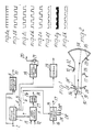
- FIG. 2 The connection of the control circuit of figure 1 to the cathode-ray tube is deduced from figure 2, in which the cathode-ray tube is generally indicated at 30.
- the cathode for the emission of the electron beam, connected to the line 14, is indicated at 31
- the vertical deflection yoke connected to the line 10 is indicated at 32
- the horizontal deflection coil connected to the line 17 is indicated at 33
- the screen including at least one photoemitting material layer for example P51 phosphorus
- the anode of the cathode-ray tube, connected to the line 20 is indicated at 36
- focusing electrodes connected to the lines 24 ⁇ -24 ⁇ and 24′′′ are indicated at 35.
- the circuit of figure 1 operates as follows.
- the vertical synchronization signal, sent to the color selection circuit 1, causes the same to supply at the output a signal associated with a base color and varying at every synchronization impulse so as to identify in sequence all the base colors provided.
- This signal thus allows the adaptation of the anodic current or voltage generated by the amplifier 19 correspondingly to the energy required to obtain the emission of the light in the base color identified by the signal supplied by the color selector.
- the color signal supplied to the switch 11 allows access to the final video amplifier 26 only of the video signal corresponding to the base color identified by the selector 1.
- the color signal supplied to the vertical deflection circuit 8 and to the horizontal deflection circuit 15 selects the amplification and possibly the waveform which must be generated by said amplifier circuits according to the characteristics which these must have depending on the different energies required for the deflection of the beam.
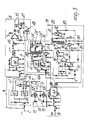
- figure 3 illustrating a circuit diagram related to the block diagram of figure 1, in the case of base signals corresponding to only two colors.
- the blocks of figure 1 have been drawn again, and therefore have been assigned the same reference numerals.
- the color selector 1 has been constructed here by means of a pair of flip-flops 41, 42 of the T type controlled at the input by a transistor 40 the base whereof is connected to the terminal 2 receiving the vertical synchronization signal. Accordingly, at every synchronization impulse, the flip-flops 41, 42 switch, generating at the output rectangular waveforms corresponding to a digital signal the high level whereof identifies a first color (for example red) and the low level whereof identifies a second base color (for example green) with respect to line 3 (see figure 4b) and vice versa as to line 4-6 (see figure 4c).
- This circuit substantially of a known type, comprises a timer 44 (constituted for example by a 555 integrated circuit) for generating at the output a saw-tooth signal which is sent to a suitable operational amplifier 45 (for example constituted by the TDA 2300 component manufactured by SGS) for the obtainment of the desired signal.
- the amplifier 45 has a system for varying the gain according to the base color transmitted at that instant, taken from the feed-back branch connecting the output 10 to an input of said amplifier 45.
- the feed-back branch has a first line comprising a potentiometer 46 (having the function of allowing the adjustment according to the cathode-ray tube actually used) and such as to provide a base amplification level corresponding to one of the transmitted colors (for example green) and a second line, in parallel with the first, comprising a second potentiometer 47 and switch means 48 controlled by the signal supplied on the line 3.
- a potentiometer 46 having the function of allowing the adjustment according to the cathode-ray tube actually used
- a second line in parallel with the first, comprising a second potentiometer 47 and switch means 48 controlled by the signal supplied on the line 3.
- the switch 48 (for example constituted by a quarter of the integrated circuit identified by 4016) causes (in the time intervals in which the video signal related to the red color is transmitted) the conduction of the switch 48 and therefore the parallel connection of the potentiometer 47 to the potentiometer 46, thus varying the gain level of the operational amplifier 45 and, finally, the level of the signal supplied at the output 10.
- the amplifier 45 is fed back only by the potentiometer 46, obtaining the intended base gain level.
- the switch of the video input 11 comprises in turn a pair of switch means 52 and 53, identical to the switch 48, and each connected to a video input 12 and 13 by means of a respective potentiometer 50 or 51. Accordingly, the signal supplied on the lines 7 ⁇ and 7 ⁇ (figures 4d and 4e), substantially in phase opposition, cause the first or the second base color to be alternately supplied towards the output 27, with a slight delay, for the reasons which will be explained in greater detail hereinafter.
- the block indicated at 15 generates the signals required for horizontal deflection for the control signals (lines 24 ⁇ -24 ⁇ ).
- said section comprises a power supply circuit 55 (for example the integrated circuit identified by L200 and manufactured by SGS) connected at an input to a pair of potentiometers 56 and 58, the latter being connected in turn to the collector of a transistor 59 receiving at the base the color signal supplied on the line 4-6.
- the potentiometer 56 supplies the base adjustment related to one of the colors (for example red)
- the other potentiometer 58 connected to the power supply 55 only during the conduction times of the transistor 59, in turn switched on or off by the color signal present on the line 4-6, allows to obtain a different adjustment related to the other base color (for example green).
- the output 61 of the timer will show a signal (shown in figure 4f) having a value variable according to the color being generated at that instant.
- Said signal is supplied to the primary of a transformer 60 the secondary whereof has a plurality of taps for the obtainment of the output 24 ⁇ related to the focus, of the output 24 ⁇ related to the power supply of the final video amplifier and of the output 24′′′ related to brightness.
- the signal used for the horizontal deflection circuit is then taken from the terminal 65 of the transformer 60.
- the terminal 65 is in fact connected to a Darlington transistor (for example the one identified by BU806 manufactured by SGS) connected at its base with the output of a timer circuit 64 (constituted for example by a 555) receiving at the input the horizontal synchronization signal. Accordingly the signal illustrated in figure 4g is obtained on the terminal 65 and, by means of suitable capacitors, is supplied to the output 17 for the control of the horizontal deflection plates.
- a Darlington transistor for example the one identified by BU806 manufactured by SGS
- a timer circuit 64 constituted for example by a 555
- the timer circuit 64 is furthermore connected to the anodic current/voltage amplification section 19 to which the color signal supplied on the line 4-6 is also supplied.
- this color signal is supplied to a transistor 70 operating as a switch and connected with its collector to a potentiometer 71 connected to an input of an operational amplifier 73 (for example the 741).
- the same input of the operational amplifier 73 is connected to another potentiometer 72 supplying the base adjustment related to one of the colors (for example red) which is superimposed on the effect of the potentiometer 71 (related to green) during the conduction time intervals of the transistor 70, controlled by the color signal, in a manner similar to what was previously described for the potentiometers 46, 47 and 56, 58.
- the output of the amplifier 74 is then supplied to a Darlington transistor 75 at the emitter whereof, at the point 76, a signal is obtained approximately equal to that existing on the output 61 of the power supply 55 and shown in figure 4f (not in scale with the preceding ones).
- This signal is sent to a terminal of the primary of a transformer 77 the secondary whereof (supplying the anodic voltage required to obtain the convenient excitation level of the electron beam) is connected to the output 20 and to the discharge system, formed here by simple resistors 21. Accordingly the signal shown in figure 4h (not in scale with respect to the preceding ones since it is at high voltage, for example 10-15 kV) is obtained at the output on the point 81.
- the block 19 furthermore comprises a further Darlington 78 (similar to the preceding ones) controlled at the base by the timing signal supplied by the timer 64 so as to generate on its collector a signal similar to the one present on the point 65 and shown in figure 4g.
- the invention fully achieves the intended aims.
- the cost related to the monitor is considerably reduced with respect to the polychromatic monitors currently in use, these costs being further reduced by the fact that the monitor according to the invention does not require a perforated mask inside the cathode-ray tube.
- the monitor according to the invention provides a better performance as to definition both with respect to monochromatic monitors which can only use different shades of gray and with respect to color monitors in which definition is limited to the number of holes provided within the perforated mask, which limits the number of obtainable pixels.
- the invention thus conceived is susceptible to numerous modifications and variations, all within the scope of the inventive concept.
- the selector as a counter followed by a decoder-demultiplier circuit having a number of outputs equal to the number of desired base colors, each of said outputs being enabled only when the emission of the associated base color is caused.
Landscapes
- Engineering & Computer Science (AREA)
- Chemical & Material Sciences (AREA)
- Nanotechnology (AREA)
- Physics & Mathematics (AREA)
- Mathematical Physics (AREA)
- Theoretical Computer Science (AREA)
- Crystallography & Structural Chemistry (AREA)
- Multimedia (AREA)
- Signal Processing (AREA)
- Video Image Reproduction Devices For Color Tv Systems (AREA)
- Processing Of Color Television Signals (AREA)
Applications Claiming Priority (2)
| Application Number | Priority Date | Filing Date | Title |
|---|---|---|---|
| IT19217/87A IT1202455B (it) | 1987-01-30 | 1987-01-30 | Monitor policromatico per il collegamento ad apparecchiature elettriche,in particolare di tipo numerico |
| IT1921787 | 1987-01-30 |
Publications (2)
| Publication Number | Publication Date |
|---|---|
| EP0276786A2 true EP0276786A2 (de) | 1988-08-03 |
| EP0276786A3 EP0276786A3 (de) | 1990-02-07 |
Family
ID=11155878
Family Applications (1)
| Application Number | Title | Priority Date | Filing Date |
|---|---|---|---|
| EP88100992A Withdrawn EP0276786A3 (de) | 1987-01-30 | 1988-01-23 | Polychromatischer Monitor zur Verbindung mit elektrischen, insbesondere digitalen Geräten |
Country Status (2)
| Country | Link |
|---|---|
| EP (1) | EP0276786A3 (de) |
| IT (1) | IT1202455B (de) |
Family Cites Families (4)
| Publication number | Priority date | Publication date | Assignee | Title |
|---|---|---|---|---|
| US3413410A (en) * | 1966-02-04 | 1968-11-26 | Polaroid Corp | Color television system with means for reducing kinescope misregistration |
| GB1331265A (en) * | 1970-08-14 | 1973-09-26 | Redifon Ltd | Electronic switching circuit arrangements |
| US4430667A (en) * | 1982-01-04 | 1984-02-07 | International Business Machines Corporation | Apparatus for obtaining multicolor raster images using a voltage penetration screen CRT |
| GB2134759B (en) * | 1983-02-09 | 1986-09-24 | Secr Defence | Colour head-up display |
-
1987
- 1987-01-30 IT IT19217/87A patent/IT1202455B/it active
-
1988
- 1988-01-23 EP EP88100992A patent/EP0276786A3/de not_active Withdrawn
Also Published As
| Publication number | Publication date |
|---|---|
| IT8719217A0 (it) | 1987-01-30 |
| EP0276786A3 (de) | 1990-02-07 |
| IT1202455B (it) | 1989-02-09 |
Similar Documents
| Publication | Publication Date | Title |
|---|---|---|
| US4449148A (en) | Image display apparatus | |
| EP0057836A2 (de) | Bildwiedergabegerät | |
| EP0094622A1 (de) | Bildwiedergabegerät | |
| JPS6221318B2 (de) | ||
| US3930120A (en) | Multi-beam cathode ray tube having equalized line brightness | |
| US3887838A (en) | Generation of stepped voltages for color television and the like | |
| US4408143A (en) | Color image display apparatus | |
| US2965704A (en) | Colour television and like systems | |
| US3944882A (en) | Centering circuits employed for beam deflection circuits | |
| US4535272A (en) | Image display apparatus | |
| EP0079604B1 (de) | Bildwiedergabevorrichtung | |
| US2473276A (en) | Color television system | |
| US4476485A (en) | Constant current bias color switch for a beam penetration CRT | |
| US3258642A (en) | Electron beam convergence apparatus | |
| US2725418A (en) | Color television receiving system | |
| US3524013A (en) | Stable monochrome balance circuit for single gun display tube | |
| US2759992A (en) | Manual color sync control | |
| US4794449A (en) | Electron multiplier flat CRT display apparatus providing successive color scanning lines for each scanning line of a received color video signal | |
| KR100320471B1 (ko) | 디스플레이 장치, 구동장치 및 구동방법 | |
| US2792446A (en) | Color television apparatus | |
| JPH0567109B2 (de) | ||
| JP2652387B2 (ja) | 画像表示装置 | |
| US5065077A (en) | Color monitor | |
| SU1681402A1 (ru) | Устройство регулировки ркости и баланса белого электронно-лучевой трубки | |
| GB2273425A (en) | Cathode ray tube display with improved beam current control. |
Legal Events
| Date | Code | Title | Description |
|---|---|---|---|
| PUAI | Public reference made under article 153(3) epc to a published international application that has entered the european phase |
Free format text: ORIGINAL CODE: 0009012 |
|
| AK | Designated contracting states |
Kind code of ref document: A2 Designated state(s): DE ES FR GB |
|
| PUAL | Search report despatched |
Free format text: ORIGINAL CODE: 0009013 |
|
| AK | Designated contracting states |
Kind code of ref document: A3 Designated state(s): DE ES FR GB |
|
| STAA | Information on the status of an ep patent application or granted ep patent |
Free format text: STATUS: THE APPLICATION IS DEEMED TO BE WITHDRAWN |
|
| 18D | Application deemed to be withdrawn |
Effective date: 19900801 |