EP0276838A1 - Farbkathodenstrahlröhre - Google Patents
Farbkathodenstrahlröhre Download PDFInfo
- Publication number
- EP0276838A1 EP0276838A1 EP19880101187 EP88101187A EP0276838A1 EP 0276838 A1 EP0276838 A1 EP 0276838A1 EP 19880101187 EP19880101187 EP 19880101187 EP 88101187 A EP88101187 A EP 88101187A EP 0276838 A1 EP0276838 A1 EP 0276838A1
- Authority
- EP
- European Patent Office
- Prior art keywords
- panel
- skirt
- pins
- cathode ray
- ray tube
- Prior art date
- Legal status (The legal status is an assumption and is not a legal conclusion. Google has not performed a legal analysis and makes no representation as to the accuracy of the status listed.)
- Granted
Links
- OAICVXFJPJFONN-UHFFFAOYSA-N Phosphorus Chemical compound [P] OAICVXFJPJFONN-UHFFFAOYSA-N 0.000 claims description 32
- 238000010276 construction Methods 0.000 claims description 18
- 230000002093 peripheral effect Effects 0.000 claims description 8
- 239000011521 glass Substances 0.000 description 14
- 239000002002 slurry Substances 0.000 description 14
- 238000000034 method Methods 0.000 description 9
- 230000035939 shock Effects 0.000 description 6
- 238000004519 manufacturing process Methods 0.000 description 5
- 230000015572 biosynthetic process Effects 0.000 description 4
- 239000006060 molten glass Substances 0.000 description 4
- 238000000465 moulding Methods 0.000 description 3
- 230000007423 decrease Effects 0.000 description 2
- 230000002542 deteriorative effect Effects 0.000 description 2
- 238000010894 electron beam technology Methods 0.000 description 2
- 239000012141 concentrate Substances 0.000 description 1
- 238000005336 cracking Methods 0.000 description 1
- 230000006866 deterioration Effects 0.000 description 1
- 238000010438 heat treatment Methods 0.000 description 1
- 238000002844 melting Methods 0.000 description 1
- 230000008018 melting Effects 0.000 description 1
- 238000012986 modification Methods 0.000 description 1
- 230000004048 modification Effects 0.000 description 1
- 238000003825 pressing Methods 0.000 description 1
- 230000000630 rising effect Effects 0.000 description 1
- 238000009736 wetting Methods 0.000 description 1
Images

Classifications
-
- H—ELECTRICITY
- H01—ELECTRIC ELEMENTS
- H01J—ELECTRIC DISCHARGE TUBES OR DISCHARGE LAMPS
- H01J29/00—Details of cathode-ray tubes or of electron-beam tubes of the types covered by group H01J31/00
- H01J29/02—Electrodes; Screens; Mounting, supporting, spacing or insulating thereof
- H01J29/06—Screens for shielding; Masks interposed in the electron stream
- H01J29/07—Shadow masks for colour television tubes
- H01J29/073—Mounting arrangements associated with shadow masks
Definitions
- This invention relates to a color cathode ray tube and more particularly to a color cathode ray tube panel having an improved panel pin mounting construction for supporting a shadow mask.
- panel pins for supporting a shadow mask are fixed to a panel.
- the panel pins are fixed on the skirt of the panel.
- fixing on the panel skirt there are two methods: one is that the panel pins are fixed embedded at about the center points of four inner side sections of the skirt and the other is that the panel pins are fixed embedded at four corner sections of the skirt as disclosed in U.S. Patent No. 4,652,792.
- panel pins are integral bodies, each consisting of a taper section connected with an elastic support member and a cylindrical embedded section to be embedded in a corner of a panel, leaving the taper section projecting.
- the embedded section cannot be embedded in the corner section to a uniform depth around its periphery because the inner surface of the corner section is curved. The result is an insufficient embedded strength of panel pins.
- cathode ray tubes named FS tube (tradename) which are disclosed in U.S. Patent Nos. 4,537,321, 4,537,322 and 4,535,907 and Serial No. 844,553 filed on March 28, 1986
- the curvature of the corner sections of the panel is large in every case, resulting in low mounting strength and low embedding accuracy of the panel pins.
- the weight of the shadow mask is so great as to liable to impose a large load on the panel pins and therefore, the panel pins are required to have a high mounting strength.
- panel pins are embedded in curved corner sections, four panel pins cannot be positioned with accuracy so high as in embedding in flat skirt sections. Panel pins tend to be mounted off specified positions or a specified angle. If the panel pins are mounted with poor accuracy, a shadow mask cannot be held in correct position by panel pins. Consequently, phosphor stripes, which are formed by exposure through apertures of a shadow mask, cannot be arranged in correct position, deteriorating color reproducibility or making color adjustment difficult in a completed color cathode ray tube. In a structure in which the panel pins are embedded at the corner sections such that the panel pins are incorrectly inclined or positioned, the embedded depth is more uneven around their peripheries and therefore, the embedded strength is more reduced.
- panels are molded by pressing molten glass in a mold.
- a plunger that presses molten glass is pulled out of the mold before the molten glass solidifies, that is to say, an unsolidified glass panel comes out of the mold, thus entailing a possibility that the skirt of the glass panel inclines slightly either inside or outside. This slight inclination of the skirt is liable to deteriorate the mounting accuracy. To avoid this, delicate adjustments are required.
- panel pins need to be embedded in the skirt deeper than normally in order to secure specified diagonal dimensions between two pairs of diagonally opposite panel pins.
- panel pins need to be embedded in the skirt shallower than normally in order to secure specified diagonal dimensions between two pairs of diagonally opposite panel pins.
- a phosphor screen is made as follows. A glass panel is rotated, a phosphor slurry is introduced to the substantially central portion of the rotating panel, the phosphor slurry is spread along the inner surface of the faceplate by the use of centrifugal force and excess phosphor slurry that has reached the skirt is collected from the skirt. In this process, the excess phosphor slurry collects at the corners of the panel where the centrifugal force acts greatest and is discharged from the corners to the outside of the panel.
- the skirt is sharp-cornered, making phosphor slurry concentrate at the corners and increasing the possibility of its adhering to the panel pins.
- the phosphor slurry adhering to the panel pins deteriorates the repeatability of shadow mask mounting operations and, if it falls off, decreases the dielectric strength of the color cathode ray tube.
- This invention relates to a color cathode ray tube in which panel pins are mounted at the corners of a skirt of a panel substantially rectangular in the front view and the panel pins are used to secure a shadow mask.
- the object of this invention is to provide a color cathode ray tube of the above-mentioned constructional type which has been improved in the mounting strength and accuracy of panel pins and which has a constructional feature to prevent phosphor from adhering to the panel pins when a phosphor screen is formed.
- the panel construction of a color cathode ray tube comprises a faceplate having curved outer and inner surfaces, a front view of said inner surface on which a phosphor layer is formed being substantially rectangular; a skirt with some thickness extending from a peripheral edge of said faceplate and having four corner sections, each of said corner sections being provided with a mount base so as to be thicker than said skirt and having an outer surface curved with some curvature and an inner surface defined as a surface of the mount base, the curvature of which is smaller than the curvature of the outer surface; four panel pins fixed to corresponding mount bases of said skirt, said panel pins projecting in diagonal directions of said faceplate; and a shadow mask supported by said four panel pins.
- Fig. 1 shows a color cathode ray tube incorporating a panel pin mounting construction according to an embodiment of this invention.
- envelope 5 of a color cathode ray tube is made of glass and includes neck 11 which accommodates electron gun 13, funnel 4 which has an opening extending from neck 11 and panel 3 which is fusion-joined to the opening of funnel 4.
- panel 3 has faceplate 1 and skirt 2 extending from a peripheral edge of faceplate 1 to funnel 4 and faceplate 1 has formed on its inner surface screen 6 consisting of a three color phosphor layer.
- Shadow mask 7, which is of a substantially rectangular shape, is arranged in panel 3 to oppose phosphor screen 6.
- Shadow mask 7 comprises mask section 31 having a large number of apertures of specified shape for allowing passage of electron beams therethrough and frame 32 having an L-like cross section and extending from a peripheral edge of shadow mask 7.
- Shadow mask 7 is mounted to panel 3 by connecting elastic support members 9, which has a substantially U-like cross section and fixed at corners of an outer peripheral wall of frame 32, to panel pins 10 secured at corners of skirt 2.
- elastic support members 9 which has a substantially U-like cross section and fixed at corners of an outer peripheral wall of frame 32, to panel pins 10 secured at corners of skirt 2.
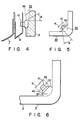
- each mount base 33 has a substantially triangular cross section, formed by two sides of a corner of skirt 2.
- each mount baase 33 extends from the point of border between faceplate 1 and skirt 2 toward the opening in almost parallel with the panel axis (which is coincident with the tube axis) in contrast to the sloped peripheral inner surface of skirt 2 other than the positions of the panel pin mount bases as shown in Fig. 3. Therefore, at the opening end of the panel, the end portions of the mount bases project toward the center of panel 3.
- Each panel pin mount surface 36 is formed such that is intersects almost perpendicularly to the axis of panel pin 10 when panel pin 10 is mounted correctly.
- Panel pins 10 are installed by melting the specified positions of panel pin mount bases 33 with a gas burner or by high frequency heating and embedding them in the melted positions.
- panel mount bases 33 having mount surfaces 36 which intersect almost perpendicularly to the axes of panel pins 10 are provided at the corners of skirt 2 of panel 3 as described above, it is possible to change the flow of excess phosphor slurry discharged from the corners of skirt 2 during the formation of a phosphor screen to thereby prevent the phosphor from adhering to panel pins 10.
- the surface area of panel pin mount surface 36 shown in Fig. 3 is wider than in the conventional constructions, making the phosphor slurry flow diffused as if moving away from the panel pins 10. Further, boundary lines are formed between mount surface 36 and sides of the panel. The phosphor slurry flows concentratedly through the thus formed boundary corners and this also serves to prevent the adhesion of the phosphor slurry to panel pins 10. Therefore, it is possible to prevent a deterioration in repeatability of shadow mask mounting operations due to the adhesion of phosphor slurry.
- panel pins 10 can be easily embedded uniformly around their peripheries to a fixed depth and with a wetting angle of preferably 40° at which the embedded strength is greatest.
- the mounting strength of panel pins 10 can be obtained which is higher than in the conventional mounting constructions.
- the provision of flat mount bases as described above reduces the deformation of the corners of skirt 2 during the formation of panel 3.
- panel pin mount bases 33 each have a flat surface, panel pins 10 can be embedded to any desired depth using this flat surface as the reference face. Hence, the mounting accuracy is high, ensuring high repeatability of mounting and dismounting operations of shadow masks. As a result color cathode ray tubes which display good-quality pictures can be produced.
- the improved mounting accuracy stabilizes the embedded depth of panel pins 10, thereby preventing cracks that used to occur owing to the low mounting accuracy of the panel pins.
- the provision of flat mount bases 33 makes it possible to increase the thickness of the corners of the panel, which offers a higher strength to the panel to guard against its deformation by atmospheric pressure. As a result, color cathode ray tubes having high strength against implosion of the envelope can be produced.
- mount base 40 there is formed at the corner of skirt 2 of panel 3, mount base 40 to provide recesses 37 between panel pin mount surface 36 and the inner surface of skirt 2, in addition to panel pin mount surface 36.
- mount base 40 of this configuration makes it possible to effectively limit the passage of excess phosphor slurry coming out of the corners during the formation of a phosphor screen, providing less chances for the phosphor to adhere to panel pins 10.
- panel pins 10 can be improved if they are embedded in such a way that the center axes of panel pins intersect tube axis 35 at right angles.
- the panel pin mount construction according to this invention should preferably be applied particularly to color cathode ray tubes disclosed in U.S. Patent Nos. 4,537,321, 4,537,322 and 4,535,907. By so doing, the above-described advantages can be obtained securely.
Landscapes
- Electrodes For Cathode-Ray Tubes (AREA)
- Vessels, Lead-In Wires, Accessory Apparatuses For Cathode-Ray Tubes (AREA)
Applications Claiming Priority (4)
| Application Number | Priority Date | Filing Date | Title |
|---|---|---|---|
| JP1522687 | 1987-01-27 | ||
| JP15226/87 | 1987-01-27 | ||
| JP62323733A JP2736064B2 (ja) | 1987-01-27 | 1987-12-23 | カラー受像管 |
| JP323733/87 | 1987-12-23 |
Publications (2)
| Publication Number | Publication Date |
|---|---|
| EP0276838A1 true EP0276838A1 (de) | 1988-08-03 |
| EP0276838B1 EP0276838B1 (de) | 1991-04-24 |
Family
ID=26351347
Family Applications (1)
| Application Number | Title | Priority Date | Filing Date |
|---|---|---|---|
| EP19880101187 Expired EP0276838B1 (de) | 1987-01-27 | 1988-01-27 | Farbkathodenstrahlröhre |
Country Status (5)
| Country | Link |
|---|---|
| EP (1) | EP0276838B1 (de) |
| JP (1) | JP2736064B2 (de) |
| KR (1) | KR900004258B1 (de) |
| CN (1) | CN1009778B (de) |
| DE (1) | DE3862473D1 (de) |
Cited By (4)
| Publication number | Priority date | Publication date | Assignee | Title |
|---|---|---|---|---|
| NL8902644A (nl) * | 1988-10-25 | 1990-05-16 | Samsung Electronic Devices | Schaduwmaskerframe voor kleurenbeeldbuis. |
| GB2243020A (en) * | 1990-03-16 | 1991-10-16 | Thomson Consumer Electronics | Mounting shadow mask in color cathode ray tube |
| TR24705A (tr) * | 1989-07-21 | 1992-03-01 | Thomson Consumer Electronics | Gelistirilmis goelge maskesi cercevesi donanim destegine sahip renkli resim tuepue |
| US6271624B1 (en) * | 1992-09-17 | 2001-08-07 | Sony Corporation | Cathode ray tube having a fag with spring holder |
Families Citing this family (3)
| Publication number | Priority date | Publication date | Assignee | Title |
|---|---|---|---|---|
| KR950000197Y1 (ko) * | 1991-03-15 | 1995-01-12 | 이헌조 | 칼라수상관용 새도우 마스크 조립체 |
| US5568011A (en) * | 1995-02-15 | 1996-10-22 | Thomson Consumer Electronics, Inc. | Color picture tube faceplate panel |
| CN100406814C (zh) * | 2005-07-16 | 2008-07-30 | 唐春芳 | 双吸光太阳能热水器 |
Citations (8)
| Publication number | Priority date | Publication date | Assignee | Title |
|---|---|---|---|---|
| US844553A (en) | 1900-01-22 | 1907-02-19 | Samuel J Webb | Method of compressing bales. |
| US2928967A (en) * | 1956-09-13 | 1960-03-15 | Owens Illinois Glass Co | Brackets for glass parts and method of attachment |
| US3004182A (en) * | 1958-03-13 | 1961-10-10 | Owens Illinois Glass Co | Mounting element and method of attachment to glass |
| US3832592A (en) * | 1971-07-05 | 1974-08-27 | Hitachi Ltd | Mask electrode support for color picture tube |
| US4535907A (en) | 1983-03-09 | 1985-08-20 | Tokyo Shibaura Denki Kabushiki Kaisha | Cathode-ray tube |
| US4537321A (en) | 1983-03-09 | 1985-08-27 | Tokyo Shibaura Denki Kabushiki Kaisha | Cathode-ray tube |
| US4537322A (en) | 1982-12-13 | 1985-08-27 | Tokyo Shibaura Denki Kabushiki Kaisha | Glass envelope for a cathode-ray tube |
| US4652792A (en) | 1985-03-11 | 1987-03-24 | Kabushiki Kaisha Toshiba | Color cathode ray tube with resilient shadow mask support |
Family Cites Families (2)
| Publication number | Priority date | Publication date | Assignee | Title |
|---|---|---|---|---|
| JPS5035946Y2 (de) * | 1971-07-09 | 1975-10-20 | ||
| JPS5243850U (de) * | 1975-09-20 | 1977-03-28 |
-
1985
- 1985-01-27 KR KR1019880000656A patent/KR900004258B1/ko not_active Expired
-
1987
- 1987-12-23 JP JP62323733A patent/JP2736064B2/ja not_active Expired - Lifetime
-
1988
- 1988-01-27 DE DE8888101187T patent/DE3862473D1/de not_active Expired - Lifetime
- 1988-01-27 CN CN 88100448 patent/CN1009778B/zh not_active Expired
- 1988-01-27 EP EP19880101187 patent/EP0276838B1/de not_active Expired
Patent Citations (10)
| Publication number | Priority date | Publication date | Assignee | Title |
|---|---|---|---|---|
| US844553A (en) | 1900-01-22 | 1907-02-19 | Samuel J Webb | Method of compressing bales. |
| US2928967A (en) * | 1956-09-13 | 1960-03-15 | Owens Illinois Glass Co | Brackets for glass parts and method of attachment |
| US3004182A (en) * | 1958-03-13 | 1961-10-10 | Owens Illinois Glass Co | Mounting element and method of attachment to glass |
| US3832592A (en) * | 1971-07-05 | 1974-08-27 | Hitachi Ltd | Mask electrode support for color picture tube |
| US4537322A (en) | 1982-12-13 | 1985-08-27 | Tokyo Shibaura Denki Kabushiki Kaisha | Glass envelope for a cathode-ray tube |
| US4537322B1 (en) | 1982-12-13 | 1998-03-10 | Tokyo Shibaura Electric Co | Glass envelope for a cathode-ray tube |
| US4535907A (en) | 1983-03-09 | 1985-08-20 | Tokyo Shibaura Denki Kabushiki Kaisha | Cathode-ray tube |
| US4537321A (en) | 1983-03-09 | 1985-08-27 | Tokyo Shibaura Denki Kabushiki Kaisha | Cathode-ray tube |
| US4535907B1 (en) | 1983-03-09 | 1998-03-10 | Shibaura Denki Kk | Cathode-ray tube |
| US4652792A (en) | 1985-03-11 | 1987-03-24 | Kabushiki Kaisha Toshiba | Color cathode ray tube with resilient shadow mask support |
Cited By (5)
| Publication number | Priority date | Publication date | Assignee | Title |
|---|---|---|---|---|
| NL8902644A (nl) * | 1988-10-25 | 1990-05-16 | Samsung Electronic Devices | Schaduwmaskerframe voor kleurenbeeldbuis. |
| TR24705A (tr) * | 1989-07-21 | 1992-03-01 | Thomson Consumer Electronics | Gelistirilmis goelge maskesi cercevesi donanim destegine sahip renkli resim tuepue |
| GB2243020A (en) * | 1990-03-16 | 1991-10-16 | Thomson Consumer Electronics | Mounting shadow mask in color cathode ray tube |
| GB2243020B (en) * | 1990-03-16 | 1994-09-07 | Thomson Consumer Electronics | Color picture tube |
| US6271624B1 (en) * | 1992-09-17 | 2001-08-07 | Sony Corporation | Cathode ray tube having a fag with spring holder |
Also Published As
| Publication number | Publication date |
|---|---|
| KR900004258B1 (ko) | 1990-06-18 |
| JPS63304549A (ja) | 1988-12-12 |
| DE3862473D1 (de) | 1991-05-29 |
| CN1009778B (zh) | 1990-09-26 |
| EP0276838B1 (de) | 1991-04-24 |
| CN88100448A (zh) | 1988-08-10 |
| JP2736064B2 (ja) | 1998-04-02 |
Similar Documents
| Publication | Publication Date | Title |
|---|---|---|
| EP1091381A2 (de) | Farbkathodenstrahlröhre | |
| EP0276838B1 (de) | Farbkathodenstrahlröhre | |
| US4893054A (en) | Shadow mask type color cathode ray tube | |
| US5274301A (en) | Color cathode ray tube panel with shadow mask supports | |
| JP3531879B2 (ja) | シャドウマスク形カラー陰極線管 | |
| KR100383213B1 (ko) | 칼라 음극선관 | |
| KR100344501B1 (ko) | 샤도우 마스크 조립체를 구비한 컬러 음극선관 | |
| US4866334A (en) | CRT faceplate front assembly with rigidized tension mask support structure | |
| US6225735B1 (en) | Shadow mask for color cathode-ray tube and method of manufacturing the same | |
| EP0214689B1 (de) | Farbbildröhre und Verfahren zu ihrer Herstellung | |
| EP0881659A2 (de) | Farbkathodenstrahlröhre | |
| KR100331820B1 (ko) | 평면 음극선관 | |
| US5270612A (en) | Inlaid support for an FTM mask support structure | |
| US5090933A (en) | Provision of support for tension shadow mask by which a predetermined Q-height is established without post-installation modification thereof | |
| JP2003346677A (ja) | 陰極線管用マスクフレーム | |
| US20030001481A1 (en) | Color cathode ray tube | |
| JP3264964B2 (ja) | 陰極線管の製造方法 | |
| US5047684A (en) | Mask support structure for tension mask color cathode ray tubes | |
| KR100335116B1 (ko) | 평면 음극선관의 섀도우마스크 고정장치 | |
| KR20000011727A (ko) | 섀도우마스크형컬러음극선관 | |
| KR100524861B1 (ko) | 음극선관용 마스크 프레임 | |
| US6388371B1 (en) | Color cathode ray tube and method for manufacturing a shadow mask for a color cathode ray tube | |
| JPS61203538A (ja) | カラ−ブラウン管 | |
| JPH0778571A (ja) | カラー受像管 | |
| JPH09306352A (ja) | カラー受像管装置の製造方法 |
Legal Events
| Date | Code | Title | Description |
|---|---|---|---|
| PUAI | Public reference made under article 153(3) epc to a published international application that has entered the european phase |
Free format text: ORIGINAL CODE: 0009012 |
|
| 17P | Request for examination filed |
Effective date: 19880224 |
|
| AK | Designated contracting states |
Kind code of ref document: A1 Designated state(s): DE FR GB |
|
| 17Q | First examination report despatched |
Effective date: 19890814 |
|
| GRAA | (expected) grant |
Free format text: ORIGINAL CODE: 0009210 |
|
| AK | Designated contracting states |
Kind code of ref document: B1 Designated state(s): DE FR GB |
|
| REF | Corresponds to: |
Ref document number: 3862473 Country of ref document: DE Date of ref document: 19910529 |
|
| ET | Fr: translation filed | ||
| PLBI | Opposition filed |
Free format text: ORIGINAL CODE: 0009260 |
|
| 26 | Opposition filed |
Opponent name: SCHOTT GLASWERKE Effective date: 19911130 |
|
| PGFP | Annual fee paid to national office [announced via postgrant information from national office to epo] |
Ref country code: FR Payment date: 19940111 Year of fee payment: 7 |
|
| PGFP | Annual fee paid to national office [announced via postgrant information from national office to epo] |
Ref country code: GB Payment date: 19940118 Year of fee payment: 7 |
|
| PGFP | Annual fee paid to national office [announced via postgrant information from national office to epo] |
Ref country code: DE Payment date: 19940121 Year of fee payment: 7 |
|
| RDAG | Patent revoked |
Free format text: ORIGINAL CODE: 0009271 |
|
| STAA | Information on the status of an ep patent application or granted ep patent |
Free format text: STATUS: PATENT REVOKED |
|
| 27W | Patent revoked |
Effective date: 19940714 |
|
| GBPR | Gb: patent revoked under art. 102 of the ep convention designating the uk as contracting state |
Free format text: 940714 |