EP0276896B1 - Optisches Informations-Aufnahme/-Wiedergabegerät - Google Patents
Optisches Informations-Aufnahme/-Wiedergabegerät Download PDFInfo
- Publication number
- EP0276896B1 EP0276896B1 EP88200150A EP88200150A EP0276896B1 EP 0276896 B1 EP0276896 B1 EP 0276896B1 EP 88200150 A EP88200150 A EP 88200150A EP 88200150 A EP88200150 A EP 88200150A EP 0276896 B1 EP0276896 B1 EP 0276896B1
- Authority
- EP
- European Patent Office
- Prior art keywords
- lens
- recording medium
- optical system
- objective lens
- photodetector
- Prior art date
- Legal status (The legal status is an assumption and is not a legal conclusion. Google has not performed a legal analysis and makes no representation as to the accuracy of the status listed.)
- Expired - Lifetime
Links
- 230000003287 optical effect Effects 0.000 title claims description 71
- 230000004075 alteration Effects 0.000 claims description 26
- 239000004065 semiconductor Substances 0.000 claims description 13
- 230000005855 radiation Effects 0.000 claims description 5
- 239000002131 composite material Substances 0.000 description 4
- 238000000034 method Methods 0.000 description 4
- 230000010355 oscillation Effects 0.000 description 4
- 230000002411 adverse Effects 0.000 description 1
- 238000001514 detection method Methods 0.000 description 1
- 230000000694 effects Effects 0.000 description 1
- 230000005499 meniscus Effects 0.000 description 1
Images
Classifications
-
- G—PHYSICS
- G11—INFORMATION STORAGE
- G11B—INFORMATION STORAGE BASED ON RELATIVE MOVEMENT BETWEEN RECORD CARRIER AND TRANSDUCER
- G11B11/00—Recording on or reproducing from the same record carrier wherein for these two operations the methods are covered by different main groups of groups G11B3/00 - G11B7/00 or by different subgroups of group G11B9/00; Record carriers therefor
- G11B11/10—Recording on or reproducing from the same record carrier wherein for these two operations the methods are covered by different main groups of groups G11B3/00 - G11B7/00 or by different subgroups of group G11B9/00; Record carriers therefor using recording by magnetic means or other means for magnetisation or demagnetisation of a record carrier, e.g. light induced spin magnetisation; Demagnetisation by thermal or stress means in the presence or not of an orienting magnetic field
- G11B11/105—Recording on or reproducing from the same record carrier wherein for these two operations the methods are covered by different main groups of groups G11B3/00 - G11B7/00 or by different subgroups of group G11B9/00; Record carriers therefor using recording by magnetic means or other means for magnetisation or demagnetisation of a record carrier, e.g. light induced spin magnetisation; Demagnetisation by thermal or stress means in the presence or not of an orienting magnetic field using a beam of light or a magnetic field for recording by change of magnetisation and a beam of light for reproducing, i.e. magneto-optical, e.g. light-induced thermomagnetic recording, spin magnetisation recording, Kerr or Faraday effect reproducing
- G11B11/10532—Heads
-
- G—PHYSICS
- G02—OPTICS
- G02B—OPTICAL ELEMENTS, SYSTEMS OR APPARATUS
- G02B19/00—Condensers, e.g. light collectors or similar non-imaging optics
- G02B19/0004—Condensers, e.g. light collectors or similar non-imaging optics characterised by the optical means employed
- G02B19/0009—Condensers, e.g. light collectors or similar non-imaging optics characterised by the optical means employed having refractive surfaces only
- G02B19/0014—Condensers, e.g. light collectors or similar non-imaging optics characterised by the optical means employed having refractive surfaces only at least one surface having optical power
-
- G—PHYSICS
- G02—OPTICS
- G02B—OPTICAL ELEMENTS, SYSTEMS OR APPARATUS
- G02B19/00—Condensers, e.g. light collectors or similar non-imaging optics
- G02B19/0033—Condensers, e.g. light collectors or similar non-imaging optics characterised by the use
- G02B19/0047—Condensers, e.g. light collectors or similar non-imaging optics characterised by the use for use with a light source
- G02B19/0052—Condensers, e.g. light collectors or similar non-imaging optics characterised by the use for use with a light source the light source comprising a laser diode
-
- G—PHYSICS
- G02—OPTICS
- G02B—OPTICAL ELEMENTS, SYSTEMS OR APPARATUS
- G02B19/00—Condensers, e.g. light collectors or similar non-imaging optics
- G02B19/0033—Condensers, e.g. light collectors or similar non-imaging optics characterised by the use
- G02B19/0085—Condensers, e.g. light collectors or similar non-imaging optics characterised by the use for use with both a detector and a source
-
- G—PHYSICS
- G11—INFORMATION STORAGE
- G11B—INFORMATION STORAGE BASED ON RELATIVE MOVEMENT BETWEEN RECORD CARRIER AND TRANSDUCER
- G11B7/00—Recording or reproducing by optical means, e.g. recording using a thermal beam of optical radiation by modifying optical properties or the physical structure, reproducing using an optical beam at lower power by sensing optical properties; Record carriers therefor
- G11B7/08—Disposition or mounting of heads or light sources relatively to record carriers
- G11B7/09—Disposition or mounting of heads or light sources relatively to record carriers with provision for moving the light beam or focus plane for the purpose of maintaining alignment of the light beam relative to the record carrier during transducing operation, e.g. to compensate for surface irregularities of the latter or for track following
- G11B7/0901—Disposition or mounting of heads or light sources relatively to record carriers with provision for moving the light beam or focus plane for the purpose of maintaining alignment of the light beam relative to the record carrier during transducing operation, e.g. to compensate for surface irregularities of the latter or for track following for track following only
-
- G—PHYSICS
- G11—INFORMATION STORAGE
- G11B—INFORMATION STORAGE BASED ON RELATIVE MOVEMENT BETWEEN RECORD CARRIER AND TRANSDUCER
- G11B7/00—Recording or reproducing by optical means, e.g. recording using a thermal beam of optical radiation by modifying optical properties or the physical structure, reproducing using an optical beam at lower power by sensing optical properties; Record carriers therefor
- G11B7/08—Disposition or mounting of heads or light sources relatively to record carriers
- G11B7/09—Disposition or mounting of heads or light sources relatively to record carriers with provision for moving the light beam or focus plane for the purpose of maintaining alignment of the light beam relative to the record carrier during transducing operation, e.g. to compensate for surface irregularities of the latter or for track following
- G11B7/0908—Disposition or mounting of heads or light sources relatively to record carriers with provision for moving the light beam or focus plane for the purpose of maintaining alignment of the light beam relative to the record carrier during transducing operation, e.g. to compensate for surface irregularities of the latter or for track following for focusing only
-
- G—PHYSICS
- G11—INFORMATION STORAGE
- G11B—INFORMATION STORAGE BASED ON RELATIVE MOVEMENT BETWEEN RECORD CARRIER AND TRANSDUCER
- G11B7/00—Recording or reproducing by optical means, e.g. recording using a thermal beam of optical radiation by modifying optical properties or the physical structure, reproducing using an optical beam at lower power by sensing optical properties; Record carriers therefor
- G11B7/12—Heads, e.g. forming of the optical beam spot or modulation of the optical beam
-
- G—PHYSICS
- G11—INFORMATION STORAGE
- G11B—INFORMATION STORAGE BASED ON RELATIVE MOVEMENT BETWEEN RECORD CARRIER AND TRANSDUCER
- G11B7/00—Recording or reproducing by optical means, e.g. recording using a thermal beam of optical radiation by modifying optical properties or the physical structure, reproducing using an optical beam at lower power by sensing optical properties; Record carriers therefor
- G11B7/12—Heads, e.g. forming of the optical beam spot or modulation of the optical beam
- G11B7/135—Means for guiding the beam from the source to the record carrier or from the record carrier to the detector
- G11B7/1372—Lenses
- G11B7/1378—Separate aberration correction lenses; Cylindrical lenses to generate astigmatism; Beam expanders
Definitions
- the present invention relates to an optical information recording/reproducing apparatus comprising: means for directing a radiation beam to a recording medium; and means for detecting a beam from the recording medium, said means including a photodetector and a condensing optical system for condensing the beam from the recording medium onto said photodetector.
- a beam spot modulated by information is applied on a surface of the medium to change optical characteristics of the medium, or reflected light is detected, which is modulated in accordance with the information recorded on the surface of the medium.
- An optical system used in an apparatus of this type is constituted by an objective lens system for forming a beam spot on the surface of a medium, and a lens system for condensing light onto a photodetector which is used for detecting information recorded on the medium and for detecting a servo signal for AF and AT control.
- JP-A-61.20918 discloses a specific design for correcting aberration in an objective lens.
- Japanese Patent Laid-Open No. 3110/1986 discloses a technique wherein an achromatic lens is used in the objective lens system.
- the achromatic lens is merely designed such that light beams of two different wavelengths are focused at an identical position. Therefore, again, this technique cannot prevent an adverse influence on a servo detection system caused by changes in aberration in the condensing optical system due to fluctuations in wavelength.
- the optical information recording/reproducing apparatus of the above-described type is characterized in that said condensing optical system is corrected for on-axis chromatic aberration by being constituted by a telescopic system including a first lens group and a second lens group, said first lens group having a positive refractive power ⁇ p and being arranged at a side of the recording medium and said second lens group having a negative refractive power ⁇ n and being arranged at a side of the photodetector, wherein for a normalised condensing optical system having a unit focal length the following relation is met: wherein for a normalised condensing optical system having a unit focal length the following relation is met: where
- each lens group is constituted by a plurality of lenses
- a refracting power ⁇ of each lens group is represented by a composite reflective power of the lenses
- the Abbe's number ⁇ of each lens group can be regarded as a composite (average) Abbe's number of the Abbe's numbers of the lenses.
- each lens group is regarded as a single lens.
- an oscillation wavelength is varied due to a change in temperature.
- an optical information recording/reproducing apparatus in which such as an optomagnetic disk apparatus or a phase-change type after-write disk is used and which requires a plurality of modes, e.g., recording, reproducing, and erase modes, variations in wavelength due to a change in output from the semiconductor laser upon switching the modes occur.
- a condensing or focusing optical system for guiding light obtained from a surface of a medium through an objective lens toward a photodetector is constituted by first and second lens groups arranged from the side of the surface of the medium.
- the first lens group comprises a lens having a positive refracting power and the second lens group comprises a lens having a negative refracting power.
- the first lens group comprises a single convex lens and the second lens group comprises a single concave lens.
- the entire lens system need only satisfy the following relationship: ⁇ p > 60, 35 > ⁇ n (1)
- a refracting power of the single convex lens is given by ⁇ p
- a refracting power of the single concave lens is given by ⁇ n
- the coefficient L is represented by: (“Lens Design" written by Yoshiya Matsui, published by Kyoritsu Publishing Co.) where h p and h n are respectively paraxial ray incident heights. If the coefficient L is reduced, the on-axis chromatic aberration can be corrected well. For this purpose, if the following condition is satisfied: a focusing optical system, in which the chromatic aberration is
- a paraxial lateral magnification of the optical system extending from the surface of the medium to the photodetector must be increased. More specifically, a focal length of a condensing or focusing optical system for focusing, onto the photodetector, light obtained through the objective lens must be set as long as possible with respect to a focal length of the objective lens for forming a beam spot on the surface of the medium.
- the focusing optical system is constituted by a telescopic system consisting of the first lens group having the positive refracting power and the second lens group having the negative refracting power. With this arrangement, the entire system can be rendered compact, and the paraxial lateral magnification can be increased.
- Tables 1, 2, and 3 respectively show first, second, and third embodiments of a focusing optical system of the present invention.
- FNO is an f-number.
- a curvature of the surface on the side of the medium of each of a first lens near the medium and a second lens near a photodetector is set to be larger than that of the surface on the side of the photodetector.
- the first lens comprises a bi-convex positive lens
- the second lens comprises a concave meniscus lens which has a concave surface facing the side of the medium.
- the first and second lenses respectively correspond to L1 and L2 shown in Fig. 1 (to be described later).
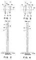
- Figs. 1, 3, and 5 are sectional views of lenses of the focusing optical systems of the embodiments shown in Tables 1 to 3.
- Figs. 2, 4, and 6 show spherical aberrations with respect to a plurality of wavelengths of the focusing optical systems shown in Figs. 1, 3, and 5, respectively.
- L1 represents a first lens group having a positive refracting power
- L2 represents a second lens group having a negative refracting power
- AX represents an optical axis.
- the first lens group L1 comprises a single convex lens, and is arranged at the side of the surface of a medium (not shown).
- the second lens group L2 comprises a single concave lens, and is arranged at the side of a photodetector (not shown).
- each of the lens groups L1 and L2 respectively comprises a single lens, but may comprise a plurality of lenses.
- each lens group comprises a single lens like in this embodiment, assembly and adjustment can be facilitated, and cost can be reduced, resulting in practical advantages.
- A represents a spherical aberration curve with respect to a wavelength of 820 nm
- B represents a spherical aberration curve with respect to a wavelength of 800 nm
- C represents a spherical aberration curve with respect to a wavelength of 780 nm
- D represents a spherical aberration curve with respect to a wavelength of 840 nm.
- a focusing optical system in which the on-axis or axial chromatic aberration is satisfactorily corrected, can be provided. Therefore, even if variations in wavelength of the light source occurs, variations in aberration in the optical system can be minimized.
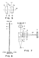
- Fig. 7 is a schematic view of an optical information recording/reproducing apparatus comprising the focusing optical system of the present invention.
- the information recording/reproducing apparatus shown in Fig. 7 includes a semiconductor laser 1, a collimator lens 2, a beam splitter 3, an objective lens 4, an information recording medium (e.g., optical disk) 5, a condensing or focusing lens 6, and a photodetector 7.
- the focusing lens 6 comprises a lens system shown in any one of Figs. 1, 3, and 5.
- the chromatic aberration of the focusing lens 6 is corrected as well as various aberrations within the range of a change in oscillation wavelength of the laser 1.
- the objective lens 4 shown in Fig. 7 comprises a single aspherical lens.
- the lens 4 may employ an optical system disclosed in U.S. Pat. No.4,657,352 (the same assignee as this application). These optical systems comprise an objective lens having one aspherical surface.
- an optical system comprising a double-aspherical surface lens or a plurality of lens elements may be employed. Not only a uniform medium optical system but also a so-called "gradient index lens" having a refracting index distribution in the medium can be used.
- a divergent laser beam emitted from the semiconductor laser 1 is collimated to a parallel laser beam by the collimator lens 2, and is then directed toward the beam splitter 3.
- the parallel laser beam passing through the beam splitter 3 is incident on the objective lens 4, and is thereby converted to a convergent laser beam. Then, the convergent laser beam is focused on the information recording surface of the information recording medium 5.
- the laser beam reflected by the information recording surface of the information recording medium 5 is directed toward the beam splitter 3 through the objective lens 4, and is then reflected by the beam splitter 3.
- the laser beam reflected by the beam splitter 3 is focused on the photodetector 7 through the focusing optical system 6.
- the focusing optical system 6 comprises two lenses. Since the chromatic aberration is corrected well, as described above, even if the oscillation wavelength of the semiconductor laser 1 is changed, the focusing optical system 6 can always focus the laser beam reflected by the information recording medium 5 onto the photodetector 7 in the best state.
- a focusing error signal or a tracking signal output from the photodetector 7 in accordance with the incident state of the reflected laser beam onto the photodetector 7 is always accurate and stable. For this reason, reliability of a recording/reproducing system can be greatly improved, and information recording/reproduction can be accurately performed.
- the objective lens 4 is moved along the optical axis AX and in a direction perpendicular to the optical axis AX based on these signals.
- Drive control of the objective lens 4 is performed by an objective lens drive mechanism (not shown), so that the laser beam is accurately focused on the surface of the information recording medium, and a laser beam spot is accurately formed on a predetermined track on the surface of the information recording medium.
- Such AF servo and AT servo are executed by a servo system of a control apparatus (not shown). The servo system is operated upon reception of the output signals from the photodetector 7.
- a driver (not shown) of the semiconductor laser 1 is controlled in accordance with the signal corresponding to information to be recorded, such that the laser beam emitted from the semiconductor laser 1 is turned on or off to form information bits along the track.
- the information recording medium 5 is moved (rotated) in a direction along the track.
- AF and AT are performed for the recording surface.
- the laser beam having a lower intensity than that in the recording mode is emitted from the semiconductor laser 1, and the beam reflected by the bits of the track on the recording surface is detected by the photodetector 7 through the objective lens 4, the beam splitter 3, and the focusing optical system 6.
- the photodetector 7 outputs a signal corresponding to the recorded information.
- the information recording medium 5 is also moved (rotated) in a direction along the track.
- AF and AT are performed.
- the objective lens 4 may comprise an achromatic lens which is subjected to chromatic-aberration correction within substantially the same wavelength range as the focusing optical system 6.
- the objective lens 4 may comprise a composite single lens disclosed in Japanese Patent Laid-Open No. 3110/1986, so that the objective lens 4 can be rendered compact and light in weight. Therefore, a load for a drive mechanism of the objective lens 4 can be reduced, and high-speed AF and AT can be realized. Since both the objective lens 4 and the focusing optical system 6 are subjected to chromatic-aberration correction, a system which is resistant and stable against variations in wavelength of the light source can be constructed.
- the collimator lens 2 normally comprises an optical system consisting of a few spherical lenses or an aspherical lens or gradient index lens similarly to the objective lens 4.
- An achromatic optical system combining the collimator lens 2 and the objective lens 4 may be provided.
- the objective lens 4 need not comprise a complex optical system such as a composite lens.
- a system which is resistant to variations in wavelength of the light source can be constructed in cooperation with the effect of the focusing optical system mentioned above.
- the focusing optical system according to the present invention is an optical system, in which the aberrations are corrected with respect to a plurality of wavelengths. For this reason, light from a surface of the information recording medium can always be satisfactorily focused on the photodetector regardless of variations in wavelength of the light source.
- an optical information recording/reproducing apparatus which is free from an influence of variations in wavelength of the light source can be provided, and highly accurate servo control such as AF and AT can be performed in the recording/reproducing mode.
Landscapes
- Physics & Mathematics (AREA)
- Optics & Photonics (AREA)
- General Physics & Mathematics (AREA)
- Lenses (AREA)
- Optical Head (AREA)
Claims (8)
- Optisches Informations-Aufnahme/-Wiedergabegerät mit:
einer Einrichtung zum Führen eines Strahles einer Strahlung zu einem Aufnahmeträger (5), und
einer Einrichtung zum Detektieren eines Strahles vom Aufnahmeträger, wobei die Einrichtung
einen Fotodetektor (7) und ein zusammenführendes, optisches System (6) zum zusammenfuhren des Strahles vom Aufnahmeträger auf den Fotodetektor hat;
dadurch gekennzeichnet, daß
das zusammenführende, optische System für eine axiale, chromatischen Abberation korrigiert wird, indem es durch ein Teleskopsystem einschließlich einer ersten Linsengruppe (L₁) und einer zweiten Linsengruppe (L₂) gebildet ist, wobei die erste Linsengruppe eine positive Brechkraft ψp hat und an einer Seite des Aufnahmeträgers angeordnet ist, und die zweite Linsengruppe eine negative Brechkraft ψn hat und an einer Seite des Fotodetektors angeordnet ist, wobei für ein normalisiertes, zusammenführendes, optisches System mit einer Systembrennweite die folgende Beziehung zutrifft:
νn die Abbesche Zahl der zweiten Linsengruppe ist. - Gerät gemäß Anspruch 1, wobei die Einrichtung zum Führen eine Kollimatorlinse (2) zur Bildung eines parallelen Strahls, eine Objektivlinse (4) zum Empfang des parallelen Strahls, um diesen auf den Aufnahmeträger zu fokusieren, und einen Strahlenteiler (3), der auf einem Weg des parallelen Strahles zwischen der Kollimatorlinse und der Objektivlinse angeordnet ist, und wobei das zusammenführende, optische System angeordnet ist, um einen Strahl vom Strahlenteiler zu empfangen, der vom Aufnahmeträger reflektiert wurde und durch die Objektivlinse im wesentlichen parallel ausgerichtet wurde.
- Optisches Informations Aufnahme/-Wiedergabegerät gemäß Anspruch 1,
wobei die Einrichtung zum Führen eine Kollimatorlinse zum Parallel-Ausrichten eines Laserstrahles eines Lasers (1) und eine Objektivlinse zum Fokusieren eines Strahles von einer Kollimatorlinse auf den Aufnahmeträger hat,
wobei die Einrichtung zum Detektieren dazu geeignet ist, einen durch den Aufnahmeträger reflektierten Strahl durch die Objektivlinse zu detektieren,
wobei der Fotodetektor zumindest ein Fokusierfehlersignal zur Anzeige eines Fokusierfehlers des Laserstrahles bezüglich dem Aufnahmeträger oder ein Nachführfehlersignal zur Anzeige eines Nachführfehlers des Laserstrahles bezüglich dem Anfnahmeträger erzeugt, und
wobei die folgende Beziehung erfüllt ist:

- Gerät gemäß Anspruch 3, wobei die Brennweite des zusammmenführenden, optischen Systems größer als die der Objektivlinse ist.
- Gerät gemäß Anspruch 3,
wobei die Einrichtung zum Führen einen Strahlenteiler hat, der zwischen der Kollimatorlinse und der Objektivlinse angeordnet ist, und
wobei die Einrichtung zum Detektieren den vom Strahlenteiler reflektierten Strahl detektiert. - Gerät gemäß Anspruch 1, wobei der Fotodetektor zumindest ein Signal zur Anzeige eines Fokusierfehlers des Strahles einer Strahlung bezüglich dem Aufnahmeträger oder ein Signal zur Anzeige eines Nachführfehlers des Strahles einer Strahlung bezüglich dem Aufnahmeträger erzeugt, der gegenüber dem Strahl, der durch das zusammenführende, optische System darauf zusammengeführt ist, empfindlich ist.
- Gerät gemäß Anspruch 6, wobei die Einrichtung zum Führen einen Halbleiterlaser hat und einen Strahl einer Strahlung vom Laser zum Aufnahmeträger führt, und die folgende Beziehung erfüllt ist:

- Gerät gemäß Anspruch 6, wobei die erste und die zweite Linsengruppe jeweils aus einem einzelnen Linsenelement bestehen.
Applications Claiming Priority (2)
| Application Number | Priority Date | Filing Date | Title |
|---|---|---|---|
| JP62020010A JPS63187213A (ja) | 1987-01-29 | 1987-01-29 | 集光光学系 |
| JP20010/87 | 1987-01-29 |
Publications (3)
| Publication Number | Publication Date |
|---|---|
| EP0276896A2 EP0276896A2 (de) | 1988-08-03 |
| EP0276896A3 EP0276896A3 (en) | 1989-02-22 |
| EP0276896B1 true EP0276896B1 (de) | 1993-12-29 |
Family
ID=12015144
Family Applications (1)
| Application Number | Title | Priority Date | Filing Date |
|---|---|---|---|
| EP88200150A Expired - Lifetime EP0276896B1 (de) | 1987-01-29 | 1988-01-28 | Optisches Informations-Aufnahme/-Wiedergabegerät |
Country Status (3)
| Country | Link |
|---|---|
| EP (1) | EP0276896B1 (de) |
| JP (1) | JPS63187213A (de) |
| DE (1) | DE3886554T2 (de) |
Families Citing this family (3)
| Publication number | Priority date | Publication date | Assignee | Title |
|---|---|---|---|---|
| JP2005284003A (ja) * | 2004-03-30 | 2005-10-13 | Fujinon Corp | 撮影レンズ |
| JP2006201604A (ja) * | 2005-01-21 | 2006-08-03 | Nikon Corp | テレフォト型屈折光学系 |
| CN111239973B (zh) * | 2020-03-12 | 2025-04-29 | 浙江舜宇光学有限公司 | 摄像光学镜头 |
Family Cites Families (3)
| Publication number | Priority date | Publication date | Assignee | Title |
|---|---|---|---|---|
| JPS5838915A (ja) * | 1981-09-01 | 1983-03-07 | Sankyo Seiki Mfg Co Ltd | 半導体レ−ザ−用コリメ−トレンズ系 |
| DE3202890A1 (de) * | 1982-01-29 | 1983-08-18 | Optische Werke G. Rodenstock, 8000 München | Farbkorrigiertes abtastobjektiv |
| JPS61275808A (ja) * | 1985-05-31 | 1986-12-05 | Asahi Optical Co Ltd | 光デイスク用レンズ |
-
1987
- 1987-01-29 JP JP62020010A patent/JPS63187213A/ja active Pending
-
1988
- 1988-01-28 EP EP88200150A patent/EP0276896B1/de not_active Expired - Lifetime
- 1988-01-28 DE DE88200150T patent/DE3886554T2/de not_active Expired - Lifetime
Also Published As
| Publication number | Publication date |
|---|---|
| JPS63187213A (ja) | 1988-08-02 |
| EP0276896A3 (en) | 1989-02-22 |
| DE3886554T2 (de) | 1994-04-28 |
| DE3886554D1 (de) | 1994-02-10 |
| EP0276896A2 (de) | 1988-08-03 |
Similar Documents
| Publication | Publication Date | Title |
|---|---|---|
| US5764613A (en) | optical pickup apparatus | |
| KR100653289B1 (ko) | 광학 헤드 및 기록 재생 장치 | |
| US5157555A (en) | Apparatus for adjustable correction of spherical aberration | |
| US6049519A (en) | Optical system for recording and reproducing for use in optical information recording medium | |
| EP0780838B1 (de) | Optisches Abtastgerät, Objektiv und konvergierendes optisches System für optisches Abtastgerät und optisches Plattengerät | |
| US4986641A (en) | Retrofocus objective lens and optical scanning device provided with such a lens | |
| US20080008078A1 (en) | Object lens for optical pickup, optical pickup and optical information processing device | |
| KR940003550B1 (ko) | 부상형 광헤드 및 광정보 기록재생장치 | |
| US5202867A (en) | Condensing optical system with corrected chromatic aberration, and information recording/reproducing apparatus using this optical system | |
| US5289313A (en) | Optical head using semiconductor laser array as light source | |
| US4965785A (en) | Optical head including a collimator having lenses of different focal lengths | |
| US20060198254A1 (en) | Objective lens, optical pickup, and optical information processing apparatus | |
| EP0594952B1 (de) | Detektorelement zum Ermitteln des Fokusfehlers und damit versehener optischer Abtaster | |
| US4927247A (en) | Objective lens for optical disk system and optical head using the same | |
| KR20030023761A (ko) | 광학 주사장치 | |
| US6151174A (en) | Device for optically scanning a record carrier | |
| US7130258B2 (en) | Field curvature reduction for optical system | |
| US6876620B2 (en) | Optical storage device | |
| US6434104B2 (en) | Objective lens, optical pickup device and optical disk device | |
| US7483345B2 (en) | Optical pickup apparatus capable of compensating thickness deviation of optical recording media | |
| US7215605B2 (en) | Optical scanning device with coma correction for improved focus tracking signal | |
| US5220553A (en) | Optical head | |
| US6741539B2 (en) | Optical system for optical head | |
| EP0276896A2 (de) | Optisches Informations-Aufnahme/-Wiedergabegerät | |
| US4687916A (en) | Optical pick-up device for both focus and error tracking detection |
Legal Events
| Date | Code | Title | Description |
|---|---|---|---|
| PUAI | Public reference made under article 153(3) epc to a published international application that has entered the european phase |
Free format text: ORIGINAL CODE: 0009012 |
|
| AK | Designated contracting states |
Kind code of ref document: A2 Designated state(s): DE FR GB IT NL |
|
| RHK1 | Main classification (correction) |
Ipc: G02B 13/00 |
|
| PUAL | Search report despatched |
Free format text: ORIGINAL CODE: 0009013 |
|
| AK | Designated contracting states |
Kind code of ref document: A3 Designated state(s): DE FR GB IT NL |
|
| 17P | Request for examination filed |
Effective date: 19890818 |
|
| 17Q | First examination report despatched |
Effective date: 19910805 |
|
| GRAA | (expected) grant |
Free format text: ORIGINAL CODE: 0009210 |
|
| AK | Designated contracting states |
Kind code of ref document: B1 Designated state(s): DE FR GB IT NL |
|
| REF | Corresponds to: |
Ref document number: 3886554 Country of ref document: DE Date of ref document: 19940210 |
|
| ET | Fr: translation filed | ||
| ITF | It: translation for a ep patent filed | ||
| PLBE | No opposition filed within time limit |
Free format text: ORIGINAL CODE: 0009261 |
|
| STAA | Information on the status of an ep patent application or granted ep patent |
Free format text: STATUS: NO OPPOSITION FILED WITHIN TIME LIMIT |
|
| 26N | No opposition filed | ||
| ITTA | It: last paid annual fee | ||
| REG | Reference to a national code |
Ref country code: GB Ref legal event code: IF02 |
|
| PGFP | Annual fee paid to national office [announced via postgrant information from national office to epo] |
Ref country code: NL Payment date: 20070115 Year of fee payment: 20 |
|
| PGFP | Annual fee paid to national office [announced via postgrant information from national office to epo] |
Ref country code: GB Payment date: 20070124 Year of fee payment: 20 |
|
| PGFP | Annual fee paid to national office [announced via postgrant information from national office to epo] |
Ref country code: DE Payment date: 20070125 Year of fee payment: 20 |
|
| PGFP | Annual fee paid to national office [announced via postgrant information from national office to epo] |
Ref country code: IT Payment date: 20070622 Year of fee payment: 20 |
|
| REG | Reference to a national code |
Ref country code: GB Ref legal event code: PE20 |
|
| NLV7 | Nl: ceased due to reaching the maximum lifetime of a patent |
Effective date: 20080128 |
|
| PG25 | Lapsed in a contracting state [announced via postgrant information from national office to epo] |
Ref country code: NL Free format text: LAPSE BECAUSE OF EXPIRATION OF PROTECTION Effective date: 20080128 |
|
| PGFP | Annual fee paid to national office [announced via postgrant information from national office to epo] |
Ref country code: FR Payment date: 20070109 Year of fee payment: 20 |
|
| PG25 | Lapsed in a contracting state [announced via postgrant information from national office to epo] |
Ref country code: GB Free format text: LAPSE BECAUSE OF EXPIRATION OF PROTECTION Effective date: 20080127 |