EP0277005A2 - Verfahren une Vorrichtung zur Erzeugung eines Abdruckes eines Hochenergielaser-Strahlenbündels - Google Patents
Verfahren une Vorrichtung zur Erzeugung eines Abdruckes eines Hochenergielaser-Strahlenbündels Download PDFInfo
- Publication number
- EP0277005A2 EP0277005A2 EP88300700A EP88300700A EP0277005A2 EP 0277005 A2 EP0277005 A2 EP 0277005A2 EP 88300700 A EP88300700 A EP 88300700A EP 88300700 A EP88300700 A EP 88300700A EP 0277005 A2 EP0277005 A2 EP 0277005A2
- Authority
- EP
- European Patent Office
- Prior art keywords
- laser beam
- energy
- replica
- reflected
- reflective
- Prior art date
- Legal status (The legal status is an assumption and is not a legal conclusion. Google has not performed a legal analysis and makes no representation as to the accuracy of the status listed.)
- Withdrawn
Links
Images

Classifications
-
- G—PHYSICS
- G02—OPTICS
- G02B—OPTICAL ELEMENTS, SYSTEMS OR APPARATUS
- G02B5/00—Optical elements other than lenses
- G02B5/20—Filters
- G02B5/205—Neutral density filters
-
- G—PHYSICS
- G02—OPTICS
- G02B—OPTICAL ELEMENTS, SYSTEMS OR APPARATUS
- G02B19/00—Condensers, e.g. light collectors or similar non-imaging optics
- G02B19/0004—Condensers, e.g. light collectors or similar non-imaging optics characterised by the optical means employed
- G02B19/0028—Condensers, e.g. light collectors or similar non-imaging optics characterised by the optical means employed refractive and reflective surfaces, e.g. non-imaging catadioptric systems
-
- G—PHYSICS
- G02—OPTICS
- G02B—OPTICAL ELEMENTS, SYSTEMS OR APPARATUS
- G02B19/00—Condensers, e.g. light collectors or similar non-imaging optics
- G02B19/0033—Condensers, e.g. light collectors or similar non-imaging optics characterised by the use
- G02B19/0076—Condensers, e.g. light collectors or similar non-imaging optics characterised by the use for use with a detector
-
- G—PHYSICS
- G02—OPTICS
- G02B—OPTICAL ELEMENTS, SYSTEMS OR APPARATUS
- G02B5/00—Optical elements other than lenses
- G02B5/003—Light absorbing elements
-
- H—ELECTRICITY
- H01—ELECTRIC ELEMENTS
- H01S—DEVICES USING THE PROCESS OF LIGHT AMPLIFICATION BY STIMULATED EMISSION OF RADIATION [LASER] TO AMPLIFY OR GENERATE LIGHT; DEVICES USING STIMULATED EMISSION OF ELECTROMAGNETIC RADIATION IN WAVE RANGES OTHER THAN OPTICAL
- H01S3/00—Lasers, i.e. devices using stimulated emission of electromagnetic radiation in the infrared, visible or ultraviolet wave range
- H01S3/005—Optical devices external to the laser cavity, specially adapted for lasers, e.g. for homogenisation of the beam or for manipulating laser pulses, e.g. pulse shaping
- H01S3/0057—Temporal shaping, e.g. pulse compression, frequency chirping
Definitions
- the present invention relates to high energy laser beam attenuation; and more particularly, to an improved method and system for producing an attenuated fiducial replica of a high energy laser beam.
- High energy laser beams are typically defined as having a peak power in the neighborhood of 15 megawatts; and may be collimated in the form of a circular beam or an annular beam having a large external diameter, in the neighborhood of 20 to 30 centimeters (8 to 12 inches), for example, in order to achieve small beam divergence.
- it has become increasingly necessary to characterize high energy laser beams, in terms of beam divergence, energy distribution in the far field footprint, and centroid behavior of beams.
- the current practice of producing a high energy laser beam replica involves intercepting the laser beam by a two dimensional diffractive beam sampler, which exhibits a very small power transmittance in the diffracted orders; and diverting the bulk of the laser energy into an optical absorber, or dump, in an essentially non-dissipative manner.
- the low energy transmitted diffracted orders are collected by suitable long focal length focusing optics to produce an attenuated far field fiducial replica of the incident high-energy laser beams in the focal plane.
- a long focal length e.g. 40 meters
- a two-dimensional beam sampler that is widely used for attenuation is a diffraction grating that is comprised of a thin highly reflective plate that is perforated with an array of small holes to provide a representative transmittance sampling over the entire area of the collimated beam.
- a two dimensional beam sampler has the ability to accommodate very high incident peak and average power levels; and the zero order, or on-axis, beam is relatively insensitive to tolerance levels in hole placement, or shift in hole locations, caused by thermal drift.
- the diameter and density of these holes control the fraction of incident laser power that is transmitted through the grating.
- the goal is to transmit the smallest fraction of laser energy, while obtaining a true representative sampling of the entire beam; and yet provide adequate angular separation between the zero order beam and adjacent diffracted orders to fully resolve the zero order beam and its sidelobes.
- This is achieved by the proper selection of hole spacing, which, of course, in turn dictates hole density, i.e. , number of holes per unit area. Once hole density is fixed, the grating transmittance is determined by the selection of hole diameter.
- a very small grating transmittance Prior to the present invention, a very small grating transmittance, and thus very small holes, were required in order to non-dissipatively deflect the bulk of the laser power. For example, if the peak zero order power of an attenuated fiducial replica in the focal plane is to be less than 0.5 watts, and the peak input power to the diffraction grating is 15 megawatts, a grating transmittance of 1.79 x 10 ⁇ 4 is necessary Thus, if an 800 micro-radian separation of adjacent orders is necessary to adequately resolve a number of 100 micro-radian features, for example, the spacing density of the holes require hole diameters of approximately 0.2 millimeters (.008 inches).
- the hole depth should not exceed approximately 25 percent of the hole diameter, or 0.05 millimeters (.002 inches), in the present example.
- the diffraction grating be made of (1) a very thin plate, which, of course, is undesirable because of lack of rigidity and lack of capability to preserve the flatness of the reflective surface; or (2) a thicker plate, with the small holes being counterbored to- within a few mils of the opposite surface, which further increases the difficulty of fabrication.
- Compact test optics are desirable in normal environments but particularly so where mobility is at stake Specifically, it is desirable that any linear dimension of a system for producing an attenuated replica be in the neighborhood of one and one-half meters, for example.
- the use of a Cassegranian optical system may be utilized to shorten the physical length of the optics while still maintaining a long effective focal length, but such a resulting system would still be longer than would be convenient for a vehicle transportable system.
- relay optics may also be considered to increase the effective focal length of the system, while still saving space, but the magnification must be kept low in order to preserve image quality when using existing camera optics, such as a Pyro-electric vidicon camera, for example, as a sensor.
- Another object of the present invention to provide such a system where the diffraction grating may be easily fabricated without the necessity of very small holes and close tolerances.
- a further object of the present invention is to provide such a system that does not degrade zero order image quality.
- a still further object of the present invention is to provide such a system that is relatively easy to align optically, simple to adjust, and relatively inexpensive to manufacture.
- a system for producing an attenuated far field fiducial replica of a high energy laser beam of the invention comprises a first deflecting means for non-dissipatively deflecting a first fraction of laser beam energy of an incident laser beam source in an angular direction to the axis of the incident beam; means for transmitting the undeflected incident laser beam energy having energy substantially greater than the replica to be produced, in a forward direction substantially parallel to the axis of the incident laser beam; means for reflecting substantially the remaining fraction of the transmitted laser beam energy in a rearward direction surrounding the axis of the laser beam source; optical folding means disposed between the transmitting means and the reflecting-means in axial alignment with the transmitted laser beam operative for re-reflecting in a forward direction surrounding the axis of the transmitted beam a fractional portion of each reflected fraction a predetermined number of times for producing in a focal plane substantially on the
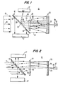
- first deflecting means includes a first or front highly reflective flat surface 13 and a second, or rear, highly reflective flat surface 28.
- Plate 12 may be oriented at a 45 degree angle to axis 14 of an incident annular laser beam 15 for deflecting a fraction of laser energy at an angle to axis 14 for absorption by an absorber or a dump 17.
- Absorber 17 may be any conventional device or material, such as firebrick, for example.
- transmitting means is comprised of a plurality of spaced holes 16 in plate 12, which are selectively spaced to form an annulus (see Figure 4) of a selected density for transmitting diffracted orders 18 of laser energy in a forward direction as represented by the direction of arrow of axis 14 of laser beam 15.
- means for reflecting transmitted diffracted orders 18 in a rearward direction surrounding the axis of a diffracted order 18 includes reflector 20 having a spherical concave surface 21 with a central aperture 22.
- optical folding means may include a partially reflective member 25 having a convex surface 26 opposing reflective surface 21, and planar surface 27 opposing flat highly reflective surface 28 of plate 12, which surface 28 constitutes second deflecting means, as herein embodied, for deflecting reflected laser energy represented by dashed lines 30 into a dump 17 ⁇ similar to dump 17.
- holes 16 in plate 12 are preferably spaced such that adjacent diffracted orders, or individual beam overlap does not occur after laser beam 15 passes through holes 16.
- diameter of holes 16 may be increased an order of magnitude, or ten times the maximum diameter that would be required for a conventional system. Such an increase in hole diameter results in a corresponding increase in the transmittance of laser energy through holes 16 by two orders of magnitude, or a hundred times more than would be permitted in conventional systems, for example. This surplus energy is subsequently removed in a non dissipative manner as will be described, thus permitting the use of large holes.
- plate 12 may have holes 16 having a diameter in the neighborhood of 2 millimeters (.08 inches) where a conventional grating would require holes having diameters in the neighborhood of 0.2 millimeters (.008 inches)
- plate 12 may have an overall thickness, if desired, in the neighborhood of 0.5 millimeters (.02 inches), since it is essential that true hole diffraction of high energy laser beam 15 occurs rather than diffraction from a cylindrical wave guide that would be simulated by a hole deeper than approximately 25 percent of hole diameter.
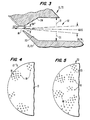
- holes 16 may be provided with a counterbore 32 to have a diameter represented by arrows 31 with such counterbore 32 tapering inwardly at peripheral surfaces 33 and 34 of holes 16.
- optical folding means include partially reflective optical member 25 which is disposed between reflective surface 28 of plate 12 and reflective surface 21 of reflector 20, and which is oriented such that the axis of member 25 is aligned with central aperture 22.
- Partially reflective member 25 as embodied in Figure 1 has a convex surface 26 opposing concave surface 21 and a planar surface 27 which opposes reflective rear surface 28.
- Surface 27 is coated with a conventional anti-reflective coating 35 that reflects approximately 1/10 of one percent of laser energy incident on planar surface 27. Approximately 17 percent of laser energy is reflected from surface 26.
- member 25 may be a lens made of zinc selenide (ZnSe) which is a material having low absorption far infrared spectrum.
- ZnSe zinc selenide
- partially reflective optical member 25 is disposed to intercept and re-reflect successive fractions (app. 17 percent) of reflected laser beam diffracted orders 18 for transmission of the attenuated replica through central aperture 22 to a focal plane referred to as 36 of Figure 1, where a sensor such as a vidicon camera 37 is to be located for characterization.
- Member 25 is so constituted and disposed at the selected distance to produce an attenuated replica having an effective focal length substantially longer than the effective focal length of primary reflector 20
- the optical folding and multiple reflections on surfaces 21 and 26 (Figure 1) not only provide for non-dissipative energy removal but also achieve a long effective focal length in a very compact form.
- the optics may be termed either "modified Cassegranian” ( Figure 1) or “thick mirror” ( Figure 2), respectively, wherein path folding, that is, reflection and re-reflection of the attenuated laser beam, achieves large multiplication factors relative to reflector 20 (or 75) focal length, coupled with a compact geometry.
- the embodiment in Figure 1 is well suited to accept laser beams of annular cross section, which is common for most expanded high energy laser beams.
- Ray 40 then reflects at point 43 to convex surface 26 of partially reflective member 25 at point 44 approximately 6.22 centimeters from optical axis 45 of lens 25. Approximately seventeen percent of the laser energy is re-reflected at point 44 back to concave spherical surface 21 at point 46 which is approximately 5.6 centimeters from the center of aperture 22. This outer ray 40 then reflects from point 46 on surface 21 to point 47 on partially reflective member 25, which is approximately 1.7 centimeters from optical axis 45. Ray 40 again re-reflects from point 47 approximately 17% of the energy reflected at 46 to pass through aperture 22 to contribute to the attenuated fiducial replica at focal plane 36 which is approximately one-tenth of a meter beyond primary reflector 20. Each time ray 40 is re-reflected from member 25, it loses all but 17 percent of its energy. Thus, with two re-reflections from surface 26, the transmitted diffracted orders lose all but approximately 0.0289 of the energy.
- Inner ray 41 strikes concave spherical surface 21 of reflector 20 approximately 8.8 centimeters from optical axis 45 at point 48. This ray 41 then reflects from point 48 to point 51 on member 25. The aforenoted fractional portion is then re-reflected from point 51 to point 52 on surface 21 which is approximately 3.3 centimeters from optical axis 45. Ray 41 is then reflected from point 52 on surface 21 to point 53 on member 25, where the power of the attenuated replica as above mentioned is re-reflected from a point of approximately 1.02 centimeters from optical axis 45 through aperture 22 to focal plane 36.
- Curve 55 near aperture 22 represents a diffraction envelope of ray 41. From the diagram it is seen that envelope 55 decreases in energy until it nulls at 56 adjacent the periphery of aperture 22. In the event that the diffraction envelope, such as 55 should be of a width that would result in undesired on-axis spillover of adjacent order energy 52 into focal plane 36, the replica at focal plane 36 would not be clear or representative of the laser beam source 15. Thus, the diameter of holes 16 are increased as previously mentioned in order to shrink envelope width of a diffraction envelope such as 55, to an optimum, or at least to an extent that a first null represented at 56 is on-axis to minimize spillover.
- single hole diffraction envelope 55 for zero order ray is centered approximately 3.3 centimeters off axis 45 with first nulls of the beam being approximately 2 54 centimeters from the axis.
- single hole diffraction envelope 55 for the inner ray trace is the ray most likely to cause undesired spillover of adjacent order energy into primary focal plane 36 in the event that holes 16 are of insufficient diameter.
- two demagnified ghost images 64 and 65 of diffraction grating 12 are formed along optical axis 45 between member 25 and reflector 20 by reflections from planar surface 27 of member 25.
- These images 64 and 65 are real, because partially reflective member 25 behaves as a bi-convex lens in the reflection mode; and this fact modifies the effective focal length of the optical system associated with the ghosts.
- ghost 65 has an effective focal length of approximately 76.7 centimeters and is located approximately 66.7 centimeters from surface 26.
- the effective focal length is 2.238 meters.
- focal lengths together with the reflection coefficients of member 25 determine power densities exhibited by on-axis foci 60 and 61 for given peak power input and beam divergence. Additional n on-axis foci 62 and 63 may be produced by energy transmitted through member 25 which is en route to energy dump 17 ⁇ . These foci 62 and 63 are less significant because they lie outside folded space between members 25 and 20 in which air breakdown must be avoided. No air breakdown is expected between members 25 and 20.
- optical system 10 comprises two spherical surfaces 21 and 26, it exhibits a natural axis of symmetry passing through the centers of curvature without regard for the orientation of members 20 and 25, respectively.
- the optical axis dictated by aiming considerations may be both laterally displaced from and make an angle with the natural axis of symmetry.
- This non-dissipative attenuation permits greater grating transmittance and thus larger grating holes for a given hole density. Also, the use of spherical reflecting surfaces such as 21 and 26 preclude undue sensitivity to positioning of the members 20 and 25, and on-axis foci power densities between members 20 and 25 are well below "contaminated" air break down levels.
- the overall system length from diffraction plate 12 to primary focal plane 36 is less than 1.5 meters and the total non-dissipative attenuation experienced by the zero order beam is greater than 50db
- system 11 produces an attenuated fiducial replica, from a laser source that may be either annular as previously described in connection with Fig. 1 such as 15, or a circular high energy laser beam such as 71, in Figure 2.
- System 11 may include a plate 72 having spaced holes such as 16 (see Figure 5) of a selected diameter and density that cover the entire area of plate 72.
- Plate 72 has a flat first or front reflective surface 73 and a rear or second surface 74 similar to the embodiment previously described.
- System 11 includes primary reflector 75 that may have an elliptical reflecting surface 76 and a central opening 22 for reflecting laser beam energy that is transmitted through holes 16.
- a transparent optical quality zinc selenide (ZnSe) plate 77 Positioned between reflector surface 76 and rear surface 74 is a transparent optical quality zinc selenide (ZnSe) plate 77 having an uncoated flat surface 78 opposing elliptical surface 76 and a flat surface 80 opposing rear reflective surface 74 of plate 72.
- Surface 80 has an anti-reflection coating for transmitting all unwanted laser energy to surface 74 of plate 72.
- the desired diffracted orders are reflected from elliptical surface 76, and re-reflected from surface 78 to elliptical surface 76, a selected number of times and then through central opening 22 to primary focal plane 36.
- the degree of attenuation and effective focal length is deter strictlymined by the number of reflections of the laser beam on uncoated surface 78 of the partially reflective member 77.
- plate 72 has holes 16 spaced over the entire surface 38 making it acceptable for either an annular or circular laser beam as previously mentioned.
Landscapes
- Physics & Mathematics (AREA)
- Optics & Photonics (AREA)
- General Physics & Mathematics (AREA)
- Electromagnetism (AREA)
- Engineering & Computer Science (AREA)
- Plasma & Fusion (AREA)
- Diffracting Gratings Or Hologram Optical Elements (AREA)
- Testing Of Optical Devices Or Fibers (AREA)
- Lasers (AREA)
- Photometry And Measurement Of Optical Pulse Characteristics (AREA)
- Optical Elements Other Than Lenses (AREA)
Applications Claiming Priority (2)
| Application Number | Priority Date | Filing Date | Title |
|---|---|---|---|
| US07/009,842 US4746205A (en) | 1987-01-30 | 1987-01-30 | High energy laser beam replica producing method and system |
| US9842 | 1987-01-30 |
Publications (2)
| Publication Number | Publication Date |
|---|---|
| EP0277005A2 true EP0277005A2 (de) | 1988-08-03 |
| EP0277005A3 EP0277005A3 (de) | 1990-03-07 |
Family
ID=21740026
Family Applications (1)
| Application Number | Title | Priority Date | Filing Date |
|---|---|---|---|
| EP88300700A Withdrawn EP0277005A3 (de) | 1987-01-30 | 1988-01-27 | Verfahren une Vorrichtung zur Erzeugung eines Abdruckes eines Hochenergielaser-Strahlenbündels |
Country Status (4)
| Country | Link |
|---|---|
| US (1) | US4746205A (de) |
| EP (1) | EP0277005A3 (de) |
| JP (1) | JPS63265131A (de) |
| CA (1) | CA1289395C (de) |
Families Citing this family (11)
| Publication number | Priority date | Publication date | Assignee | Title |
|---|---|---|---|---|
| US4945489A (en) * | 1988-05-25 | 1990-07-31 | Robolase Systems, Inc. | Laser time-sharing system |
| US5237454A (en) * | 1989-09-07 | 1993-08-17 | Blue Sky Research, Inc. | Blackhole laser beam terminator |
| GB2255483A (en) * | 1990-05-02 | 1992-11-04 | Darrell Dicicco | Beam-diverging multi-aperture diffraction plate |
| US5136413A (en) * | 1990-11-05 | 1992-08-04 | Litel Instruments | Imaging and illumination system with aspherization and aberration correction by phase steps |
| US5228051A (en) * | 1991-12-16 | 1993-07-13 | Hughes Aircraft Company | Tilted lens imager in a laser amplifier/oscillator and method utilizing same |
| US6036324A (en) * | 1997-09-17 | 2000-03-14 | Lockheed Martin Energy Research Corp | Catadioptric zoom scattering collector |
| US5940217A (en) * | 1998-05-06 | 1999-08-17 | Intel Corporation | Anti-aliasing diffractive aperture and optical system using the same |
| US6178046B1 (en) | 1999-04-21 | 2001-01-23 | Intel Corporation | Anti-aliasing diffractive aperture and method of using same |
| JP2007531918A (ja) * | 2004-04-05 | 2007-11-08 | マイクロニック レーザー システムズ アクチボラゲット | 高出力レーザー・ビーム用の開口絞りアセンブリ |
| US9612368B2 (en) * | 2014-09-16 | 2017-04-04 | Jerry Ghionis | Light reflector |
| US11881676B2 (en) * | 2019-01-31 | 2024-01-23 | L3Harris Technologies, Inc. | End-pumped Q-switched laser |
Family Cites Families (10)
| Publication number | Priority date | Publication date | Assignee | Title |
|---|---|---|---|---|
| US2916966A (en) * | 1955-06-03 | 1959-12-15 | Centre Nat Rech Scient | Catadioptric objectives |
| US3584937A (en) * | 1968-08-09 | 1971-06-15 | Olympus Optical Co | Folded reflecting microscope objective |
| US3614449A (en) * | 1969-02-12 | 1971-10-19 | Itt | Optical tracking system utilizing a coaxial lens system |
| US3748015A (en) * | 1971-06-21 | 1973-07-24 | Perkin Elmer Corp | Unit power imaging catoptric anastigmat |
| US3858046A (en) * | 1973-06-25 | 1974-12-31 | Hughes Aircraft Co | Catadioptric beamsplitter system |
| US4192573A (en) * | 1977-02-14 | 1980-03-11 | The United States Of America As Represented By The Secretary Of The Navy | Variable power attenuator for light beams |
| US4487478A (en) * | 1982-02-09 | 1984-12-11 | Pda Engineering | Laser protection device |
| US4475793A (en) * | 1982-06-01 | 1984-10-09 | Texas Instruments Incorporated | Integrated optical beam expander |
| US4576447A (en) * | 1983-09-26 | 1986-03-18 | The Boeing Company | Compact, single piece laser beam analyzer |
| US4711526A (en) * | 1986-07-07 | 1987-12-08 | Coherent, Inc. | Attenuating beam splitter |
-
1987
- 1987-01-30 US US07/009,842 patent/US4746205A/en not_active Expired - Fee Related
-
1988
- 1988-01-22 CA CA000557164A patent/CA1289395C/en not_active Expired - Lifetime
- 1988-01-27 EP EP88300700A patent/EP0277005A3/de not_active Withdrawn
- 1988-01-29 JP JP63019435A patent/JPS63265131A/ja active Pending
Also Published As
| Publication number | Publication date |
|---|---|
| CA1289395C (en) | 1991-09-24 |
| JPS63265131A (ja) | 1988-11-01 |
| US4746205A (en) | 1988-05-24 |
| EP0277005A3 (de) | 1990-03-07 |
Similar Documents
| Publication | Publication Date | Title |
|---|---|---|
| US5285318A (en) | Illumination system having an aspherical lens | |
| EP0708970B1 (de) | Roentgenstrahlungsoptik mit streifendem lichteinfall und sphaerischen spiegeln | |
| US4737021A (en) | Wide-field three-mirror collimator | |
| US3811749A (en) | Wide field reflective optical apparatus | |
| US3982824A (en) | Catoptric lens arrangement | |
| US4746205A (en) | High energy laser beam replica producing method and system | |
| US3905675A (en) | Optical systems having stop means for preventing passage of boundary wave radiation | |
| US5946143A (en) | Dynamic aberration correction of conformal/aspheric domes and windows for missile and airborne fire control applications | |
| US4756585A (en) | Optical beam scanning system | |
| Willstrop | The Mersenne–Schmidt: a three-mirror survey telescope | |
| US3752559A (en) | Ritchey-chretien telescope | |
| JPH02157808A (ja) | 放射ビーム収束装置 | |
| CA1160488A (en) | Compact optical system | |
| GB2119112A (en) | Optical elements | |
| EP1272886B1 (de) | Spiegelteleskop | |
| WO2001077734A1 (en) | Compact imaging system including an aspheric quaternary element | |
| US20070177261A1 (en) | Catadioptric telescopes | |
| US4576452A (en) | Reflective Schmidt system with nonrotationally symmetric corrector | |
| US4136926A (en) | Achromatic illumination system for small targets | |
| WO1987007392A1 (en) | Optical imaging systems | |
| US5506702A (en) | Holographic optical element providing an artificial star for an optical system | |
| EP0051969A1 (de) | Feldkrümmungskorrektion in optischen Systemen | |
| Seppala | Improved optical design for the large synoptic survey telescope (lsst) | |
| RU2238576C1 (ru) | Способ фокусировки волнового поля и устройство для его осуществления | |
| White et al. | Scanning characteristics of two-reflector antenna systems |
Legal Events
| Date | Code | Title | Description |
|---|---|---|---|
| PUAI | Public reference made under article 153(3) epc to a published international application that has entered the european phase |
Free format text: ORIGINAL CODE: 0009012 |
|
| AK | Designated contracting states |
Kind code of ref document: A2 Designated state(s): BE DE FR GB IT NL SE |
|
| PUAL | Search report despatched |
Free format text: ORIGINAL CODE: 0009013 |
|
| AK | Designated contracting states |
Kind code of ref document: A3 Designated state(s): BE DE FR GB IT NL SE |
|
| 17P | Request for examination filed |
Effective date: 19900830 |
|
| 17Q | First examination report despatched |
Effective date: 19921228 |
|
| STAA | Information on the status of an ep patent application or granted ep patent |
Free format text: STATUS: THE APPLICATION HAS BEEN WITHDRAWN |
|
| 18W | Application withdrawn |
Withdrawal date: 19940208 |