EP0277044A2 - Querstromgebläse - Google Patents
Querstromgebläse Download PDFInfo
- Publication number
- EP0277044A2 EP0277044A2 EP88300834A EP88300834A EP0277044A2 EP 0277044 A2 EP0277044 A2 EP 0277044A2 EP 88300834 A EP88300834 A EP 88300834A EP 88300834 A EP88300834 A EP 88300834A EP 0277044 A2 EP0277044 A2 EP 0277044A2
- Authority
- EP
- European Patent Office
- Prior art keywords
- fan
- air
- cross flow
- casing
- airflow
- Prior art date
- Legal status (The legal status is an assumption and is not a legal conclusion. Google has not performed a legal analysis and makes no representation as to the accuracy of the status listed.)
- Granted
Links
- 238000005192 partition Methods 0.000 claims abstract description 14
- 239000003381 stabilizer Substances 0.000 claims description 8
- 238000007664 blowing Methods 0.000 claims description 4
- 238000004378 air conditioning Methods 0.000 claims description 3
- 230000002401 inhibitory effect Effects 0.000 claims 1
- 238000010586 diagram Methods 0.000 description 24
- 238000010276 construction Methods 0.000 description 10
- 230000000694 effects Effects 0.000 description 8
- 238000009826 distribution Methods 0.000 description 5
- 230000003068 static effect Effects 0.000 description 3
- 238000012360 testing method Methods 0.000 description 3
- 238000007599 discharging Methods 0.000 description 2
- 238000002474 experimental method Methods 0.000 description 2
- 230000003292 diminished effect Effects 0.000 description 1
- 238000000034 method Methods 0.000 description 1
- 238000012986 modification Methods 0.000 description 1
- 230000004048 modification Effects 0.000 description 1
- 230000010349 pulsation Effects 0.000 description 1
- 230000000717 retained effect Effects 0.000 description 1
- 230000006641 stabilisation Effects 0.000 description 1
- 238000011105 stabilization Methods 0.000 description 1
- 230000000087 stabilizing effect Effects 0.000 description 1
- 210000005182 tip of the tongue Anatomy 0.000 description 1
Images




Classifications
-
- F—MECHANICAL ENGINEERING; LIGHTING; HEATING; WEAPONS; BLASTING
- F04—POSITIVE - DISPLACEMENT MACHINES FOR LIQUIDS; PUMPS FOR LIQUIDS OR ELASTIC FLUIDS
- F04D—NON-POSITIVE-DISPLACEMENT PUMPS
- F04D17/00—Radial-flow pumps, e.g. centrifugal pumps; Helico-centrifugal pumps
- F04D17/02—Radial-flow pumps, e.g. centrifugal pumps; Helico-centrifugal pumps having non-centrifugal stages, e.g. centripetal
- F04D17/04—Radial-flow pumps, e.g. centrifugal pumps; Helico-centrifugal pumps having non-centrifugal stages, e.g. centripetal of transverse-flow type
Definitions
- the present invention relates to a cross flow fan system which is utilized for air conditioners and various other types of air conditioning systems.
- the cross flow fan used in a conventional air conditioner is equipped with a suction opening for air and a discharge opening 2 as shown in Fig. 4, has a heat exchanger 5 and a cross flow fan 4 in the casing, and a tongue section 3 and a rear guider 6 for stabilizing the air flow.
- the hear exchanger 5 is installed so that the lower end of the heat exchanger 5 is above the shaft of the fan.
- Fig. 6 is a structural diagram of a cross flow fan for a conventional air conditioner.
- the conventional cross flow fan incorporates a cross flow fan 101 in a casing 103, and at a position close to the outer circumferential surface of the fan is provided a tongue section 102 having the same cross section (which plays a role of dividing the suction side and discharge side) in an overall area in the direction of the shaft of the fan.
- 104 represents a discharge opening.
- the discharge flow rate at both ends 104a of the fan shown in Fig. 7 is less as compared with that of the middle section 104b of the same fan and there is a possibility of generating a reverse suction flow depending on the shape of the tongue section 102, causing instability in the discharge flow rate of the fan. Furthermore, if a load 105 such as a heat exchanger is provided on the suction side of the fan, there is a possibility to easily generate surging of the discharged air flow particularly in the low air volume range.
- the conventional fan is provided with a suction opening 202 for taking in the open air at the front of the casing 201, a blow off opening 203 is provided thereunder, and a fan 204 is pivoted freely rotatably on a portion surrounded by a partition board 205 and a rear guider 201 ⁇ in the air duct connected to the blow off opening 203 from the aforementioned suction opening 202.
- the partition board 205 provided between the aforementioned suction opening 202 and the blow off opening 203 is intended to eliminate the short-circuit flow between the two openings and a blind patch is used for this purpose.
- the magnitude and position of the eddy of accessory current generated secondarily depend on the shape and installed position of the partition board 205 and the number of revolutions of the fan and other factors. In order to maintain these factors under stabilized conditions, the eccentric eddy is stabilized at a fixed position by adjusting the number of revolutions of the fan and a consideration is given so that the blown air flow without pulsation can be obtained.
- an air flow direction control blade 305a which is a flat board like blade and does not curve in either direction is provided at the discharge opening formed between the rear guide 302 enclosing the fan 301 and the stabilizer 303 of the front panel 304, and when the upward air blowing is desired, the air flow direction control blade 305a is maintained almost horizontally as shown in Fig. 18(a).
- the air flow "b" such as cold air or hot air is obtained from the blow off opening between the lower surface of the air flow direction control blade 305a and the extended upper surface of the rear guide 302 while the eddy like air flow "a ⁇ " is being generated in this space.
- the air flow direction control blade 308a is set vertically as shown in Fig.
- the air flow "b ⁇ 1" generated above the circumference of the fan 301 collides with the air flow direction control blade 305a almost at right angle because the air flow direction control blade 305a is flat, and the air flow "b ⁇ 1" is blown off downward by the internal pressure which is increased after collision.
- the present invention is accomplished in order to solve conventional problems of above.
- the cross flow fan according to the present invention is provided with a flow changing board over the entire axial direction above the portion where the rear guider and the outward circumferential surface of the fan are most close to each other.
- the cross flow fan according to the present invention is composed so that the shape of the tongue section in close vicinity to the outward circumferential surface of the fan is caused to be different at both ends of the fan and at the middle section of the fan.
- the cross flow fan according to the present invention is provided with a partition board for short-circuiting which has continuous through holes at a position on the outward circumferential surface of the fan where the suction opening and the blow off opening of the air are separated.
- the cross flow fan according to the present invention is provided with a air flow direction control blade which is curved in one direction and mounted freely pivotably at the blow off opening section formed between the rear guide enveloping the fan and the stabilizer of the front panel.
- the air flow is generated from the suction opening to the blow off opening by the rotation of the fan, and by causing a part of the air flow sent out from the blow off opening to flow back from the secondary side to the primary side of the aforementioned partition board by means of the through hole thereof, the position of the eccentric eddy is caused to be fixed by the short-circuit flow.
- the flow changing board provided above the portion where the rear guider and outward circumferential surface of the fan are most close to each other, it is possible to increase the air flow which flows through the cross flow fan and to provide an excellent effect for increasing the discharged air volume.
- the third invention is an invention of high practical value, which has an excellent effect such for example to stabilize the eccentric eddy at a fixed position without being moved by factors such as changes in the number of revolutions and the fluctuation of the load at the suction opening of the fan and to cause the discharged air volume to increase by means of a simple construction because the cross flow fan of the present invention is composed in a manner described above.
- the fourth invention is composed in a manner as described above, by using a air flow direction control blade of simple construction, it is possible to reduce the eddy current and to blow off the air at high efficiency when the aforementioned air flow direction control blade is held horizontally.
- the cross flow fan of the present invention is capable of reducing the resistance of the air flow at the blow off section so as to achieve efficient air blowing and has excellent efficiency to reduce the thickness of the cross flow fan because of simple construction.
- Fig. 1 is a structural diagram of a cross flow type fan showing an embodiment of the present invention.
- Fig. 2 is a detailed diagram of the essential components of Fig. 1.
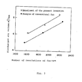
- Fig. 3 is an explanatory diagram showing experimental results wherein the cross flow type fan shown in Fig. 2 is used.
- Fig. 4 is a structural diagram of a conventional cross flow type fan.
- Fig. 5(1) and Fig. 5(2) are diagrams showing the shape of the tongue section in an embodiment of the present invention
- Fig. 5(1) shows the shape of the tongue section in the middle section in the axial direction of the fan
- Fig. 5(2) shows the shape of the tongue section at both ends in the axial direction of the fan.
- Fig. 6 is a cross sectional structural diagram of the cross flow type fan for a conventional air conditioner.
- Fig. 7 is a perspective diagram showing the discharging opening section of an air conditioner.
- Fig. 8 is a diagram showing experimental results of the static pressure distribution of the discharged air flow in case the tongue section of Fig. 5(1) and Fig. 5(2) is used.
- Fig. 5(1) and Fig. 5(2) is used.
- FIG. 9 is a diagram for comparing the wind velocity distribution in the axial direction of the fan between a case wherein the tongue section according to the present invention is used and a case wherein the conventional tongue section is used.
- Fig. 10(1) and Fig. 10(2) are diagrams respectively showing the shape of the tongue section at the middle section and at both ends in the axial direction of the fan in other embodiment of the present invention.
- Fig. 11 is a schematic diagram of the vertical side of the apparatus according to the present invention
- Fig. 12(a) and Fig. 12(b) are enlarged perspective diagrams respectively of essential components
- Fig. 13 is a schematic diagram of the vertical side of an apparatus for testing
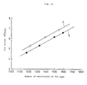
- Fig. 14 is a diagram for comparing the performance between the apparatus of the present invention and the conventional apparatus
- Fig. 15 is a schematic diagram of the vertical side showing the conventional apparatus.
- Fig. 16 and Fig. 17 respectively show embodiments of the present invention
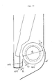
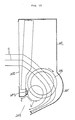
- Fig. 16 is a longitudinal sectional diagram of the air flow direction control blade
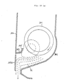
- Fig. 17(a) is a longitudinal sectional diagram showing an example of usage of the air flow direction control blade of Fig. 16
- Fig. 17(b) is a longitudinal sectional diagram showing the operation of the above
- Fig. 18(a) is a longitudinal sectional diagram of the conventional apparatus
- Fig. 18(b) is a longitudinal sectional diagram showing the operation of the conventional apparatus.
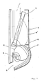
- a flow changing board 10 is provided over the entire axial direction of the fan above the portion 7 where the rear guider 6 and the outward circumferential surface of the fan are most close to each other.
- the cross flow fan 4 is rotated to suck the air into the body 1 from the suction opening 1.
- the air sucked into the body 1 gives and receives heat energy with the heat medium in the heat exchanger 5 while the air passes through the heat exchanger 5 and the air is further subjected to the driving action of the cross flow fan 4 to be discharged from the discharge opening 2.
- the air current 8 ⁇ flowing along the rear guider 6 in the casing collides with the flow changing board 10 to move toward the center of the casing, and then flows through the cross flow fan 4.
- Fig. 2 is a detailed diagram of the cross flow type fan shown in Fig. 1 which is used to confirm the effect of the above embodiment through experiments and is provided with a flow changing board 10 having a width of 15 mm with respect to the diameter of 70 mm of the cross flow fan 4.
- Fig. 3 shows an example of the test results illustrating a relation between the number of revolutions and the air volume.
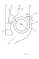
- Fig. 5(1) For the shape of the tongue section of the example 2 of the conventional cross flow fan, the one shown in Fig. 5(1) is common and is designed so as to obtain high air volume.
- Fig. 5(2) shows the shape of the tongue section whose space with the outward circumferential surface of the fan is widened by tilting (107 ⁇ ) the portion of the tongue section (tip of the tongue section) 107 in close vicinity of the outward circumferential surface of the fan so as to move away from the outward circumferential surface of the fan than the portion 107 shown in Fig. 5(1).
- Fig. 4 shows a comparison of experimental results in which the static pressure distribution at the discharge opening 4. From the results shown in Fig. 4, it is known that the shape of the tongue section shown in Fig. 5(2) has higher static pressure distribution than that shown in Fig. 5(1).
- the shape of the tongue section shown in Fig. 5(2) is provided at both ends 104a of the fan, the entire tongue section is composed in the middle section 104b by using the shape of the tongue section shown in Fig. 5(1), and by increasing the station pressure of the discharged air flow at both ends 104a of the discharge opening higher than that at the middle section 104b, the pressure characteristic of the discharged air flow at both ends 104a is improved so as to obtain better stability.
- Fig. 9 is a diagram in which the wind velocity distribution of the discharged air flow in the axial direction of the fan is compared between the case where the tongue section according to the present invention is used and the case of the tongue section of the conventional cross flow fan, and it is known that the flow rate at both ends 104a of the present invention is increased.
- the suction opening 202 for taking in the open air is provided at the front section of the casing 201 of the fan as shown in Fig. 11, the blow off opening 203 is formed thereunder, the fan 204 is pivoted freely rotatably at a portion surrounded by the lower edge 202 ⁇ of the suction opening and the rear guider 201 ⁇ in the air duct connected from the aforementioned suction opening 202 to the blow off opening 203, in the corner section between the aforementioned fan 204 and the aforementioned lower edge 202 ⁇ of the suction opening and on the aforementioned lower edge 202 ⁇ of the suction opening, the partition board 205a formed with continuous through holes 206a, 206a ... comprising one or a plurality of slots is fixed as shown in Fig. 12(a), so that the short circuit flow is caused to be generated between the suction side, that is the primary side and the blow off opening, that is, the secondary side.
- the aforementioned continuous through holes 206a, 206b ... are provided on the plane 207 formed on the partition board 205a so as to intersect almost at right angle with the outward circumferential surface of the fan 204, and in addition to the aforementioned continuous through hole 206a, circular continuous through holes 206b, 206b, ... may be drilled as shown in Fig. 12(b).
- the length of the continuous hole 206a or the diameter and the number and other factors of the circular continuous hole 206b are not limitative of the above embodiment.
- a blow off opening such for example of warm air of cool air is formed between the rear guide 302 surrounding the fan 301 and the stabilizer 303 of the front panel 304, and between the stabilizer and the frontal section 302 ⁇ of the rear guide 302 the air flow direction control blade 305 whose one end section 305 ⁇ is caused to curve upward by ⁇ (15° in this case) is installed to be held horizontally or vertically.
- the most essential point of the present invention is that when the air flow direction control blade 305 is held horizontally, the direction of the curve and inclination of the blade 305 is such that the tip 305 ⁇ thereof is caused to curve on the circumference of the fan 301 in a direction directly facing the rotational direction of the fan 301 and that when the end section 305 ⁇ of the air flow direction control blade 305 is held vertically, the other end section is composed to curve inward from the outer surface of the front panel 304 so as to extend toward the direction of the stabilizer 303.
- the air flow direction is to be directed downward, by directing vertically the end section 305 ⁇ of the air flow direction control blade 305 as shown in Fig. 17(b), the air current "b1" generated by the fan 301 blows strongly along the tip section 302 ⁇ of the rear guide 302 and the upper part of the air flow direction control blade 305 is inclined inwardly from the front surface of the front panel 304. Therefore, because the end section 305 ⁇ of the air flow direction control blade 305 does not intersects with the air current "b1" at right angle and becomes inclined toward the direction of the blow off opening, thereby reducing the flow resistance and the scale of the eddy current "a1".
- the present invention is designed to smooth the air current in a manner as described above by curving the tip of the air flow direction control blade, in order to correct the shape of the tip which causes the stagnation of the air flow.
Landscapes
- Engineering & Computer Science (AREA)
- Mechanical Engineering (AREA)
- General Engineering & Computer Science (AREA)
- Structures Of Non-Positive Displacement Pumps (AREA)
- Air-Conditioning Room Units, And Self-Contained Units In General (AREA)
Applications Claiming Priority (8)
| Application Number | Priority Date | Filing Date | Title |
|---|---|---|---|
| JP20890/87 | 1987-01-30 | ||
| JP62020890A JPS63189695A (ja) | 1987-01-30 | 1987-01-30 | クロスフロ−型送風機 |
| JP55067/87 | 1987-03-10 | ||
| JP5469387A JPS63220035A (ja) | 1987-03-10 | 1987-03-10 | 送風機の風向羽根 |
| JP54693/87 | 1987-03-10 | ||
| JP62055067A JPS63223438A (ja) | 1987-03-10 | 1987-03-10 | クロスフロ−型送風機 |
| JP1987160608U JPH0166523U (de) | 1987-10-20 | 1987-10-20 | |
| JP160608/87 | 1987-10-20 |
Publications (3)
| Publication Number | Publication Date |
|---|---|
| EP0277044A2 true EP0277044A2 (de) | 1988-08-03 |
| EP0277044A3 EP0277044A3 (en) | 1990-09-19 |
| EP0277044B1 EP0277044B1 (de) | 1996-05-29 |
Family
ID=27457474
Family Applications (1)
| Application Number | Title | Priority Date | Filing Date |
|---|---|---|---|
| EP88300834A Expired - Lifetime EP0277044B1 (de) | 1987-01-30 | 1988-02-01 | Querstromgebläse |
Country Status (3)
| Country | Link |
|---|---|
| US (2) | US4913622A (de) |
| EP (1) | EP0277044B1 (de) |
| DE (1) | DE3855315T2 (de) |
Cited By (4)
| Publication number | Priority date | Publication date | Assignee | Title |
|---|---|---|---|---|
| EP0887554A1 (de) * | 1997-06-23 | 1998-12-30 | Carrier Corporation | Strömungsstabilisator für Querstromlüfter |
| EP0823345A3 (de) * | 1996-08-05 | 2001-01-10 | Japan Climate Systems Corporation | Klimaanlage eines Fahrzeuges |
| US7235607B2 (en) | 2002-09-05 | 2007-06-26 | Exxonmobil Chemical Patents Inc. | Shrink film |
| EP3505766A4 (de) * | 2016-09-30 | 2020-04-08 | Daikin Industries, Ltd. | Querstromgebläse und innenraumeinheit einer klimaanlage damit |
Families Citing this family (11)
| Publication number | Priority date | Publication date | Assignee | Title |
|---|---|---|---|---|
| US5197850A (en) * | 1987-01-30 | 1993-03-30 | Sharp Kabushiki Kaisha | Cross flow fan system |
| US4913622A (en) * | 1987-01-30 | 1990-04-03 | Sharp Kabushiki Kaisha | Cross flow fan system |
| KR930006876B1 (ko) * | 1989-06-23 | 1993-07-24 | 가부시끼 가이샤 히다찌세이사꾸쇼 | 관류팬을 사용한 송풍장치 및 공기조화기 |
| CA2028374C (en) * | 1989-10-25 | 1994-03-29 | Toru Ichikawa | Automobile air conditioner |
| US5058434A (en) * | 1990-02-27 | 1991-10-22 | Carl Schenck Ag | Process for early detection of damage to machine parts |
| JPH09503612A (ja) * | 1993-07-16 | 1997-04-08 | バーグ・テクノロジー・インコーポレーテッド | 電気ワイヤ用コネクタ |
| KR100809784B1 (ko) * | 2006-05-20 | 2008-03-04 | 엘지전자 주식회사 | 횡류팬을 포함하는 공기 조화기 |
| US20120134794A1 (en) * | 2009-08-25 | 2012-05-31 | Mitsubishi Electric Corporation | Fan and air-conditioning apparatus provided with fan |
| WO2018029828A1 (ja) | 2016-08-10 | 2018-02-15 | 三菱電機株式会社 | 空気調和機の室内機 |
| CN114440316B (zh) * | 2022-01-30 | 2024-02-27 | 广东美的暖通设备有限公司 | 风道组件和具有其的空气调节设备 |
| CN118661026A (zh) * | 2022-02-21 | 2024-09-17 | 三菱电机株式会社 | 横流风扇 |
Family Cites Families (21)
| Publication number | Priority date | Publication date | Assignee | Title |
|---|---|---|---|---|
| US3124301A (en) * | 1964-03-10 | Helmbold | ||
| US1823579A (en) * | 1930-06-16 | 1931-09-15 | American Blower Corp | Unit heater and ventilator |
| US1920952A (en) * | 1931-01-02 | 1933-08-08 | American Blower Corp | Line flow fan |
| DE1403545A1 (de) * | 1960-01-18 | 1968-11-07 | Eck Dr Ing Bruno | Querstromgeblaese,bei dem zur Fuehrung der Durchsatzstroemang dieser im Innern des Laeufers das Feld eines Potentialwirbels ueberlagert wird |
| DE1403552A1 (de) * | 1960-03-11 | 1969-04-17 | Firth Cleveland Ltd | Luefter |
| NL144369B (nl) * | 1961-01-25 | 1974-12-16 | Daetwyler Gottfried Dr | Dwarsstroomventilator. |
| US3322332A (en) * | 1962-09-05 | 1967-05-30 | Laing Vortex Inc | Cross flow machine |
| GB1066053A (en) * | 1963-04-22 | 1967-04-19 | Hoover Ltd | Improvements relating to cross-flow machines for inducing flow of fluids |
| US3209668A (en) * | 1963-07-18 | 1965-10-05 | Carrier Corp | Air conditioning unit |
| GB1136981A (en) * | 1965-02-16 | 1968-12-18 | Firth Cleveland Ltd | Improvements relating to cross-flow fans |
| FR1446638A (fr) * | 1965-09-08 | 1966-07-22 | Karl Heinkel Appbau K G | Soufflerie, notamment du type tangentiel, dans laquelle le tambour de ventilateur est disposé dans un carter ou une partie de carter réalisé comme diffuseur |
| US3459365A (en) * | 1967-12-01 | 1969-08-05 | Torrington Mfg Co | Transverse flow blower unit having cavity with restricted opening adjacent cut-off section |
| US4014625A (en) * | 1973-08-20 | 1977-03-29 | Teruo Yamamoto | Transverse flow fan |
| DE2457183A1 (de) * | 1974-12-04 | 1976-06-10 | Braun Ag | Lueftungsoeffnung fuer geblaese mit luefterwalze |
| DE2545036B2 (de) * | 1975-10-08 | 1979-08-23 | Kurt Dr.-Ing. 7505 Ettlingen Zenkner | Gehäuse für ein Querstromgebläse |
| US4078870A (en) * | 1976-06-16 | 1978-03-14 | International Standard Electric Corporation | Tangential blower |
| SU901642A2 (ru) * | 1980-04-09 | 1982-01-30 | Предприятие П/Я Г-4974 | Диаметральный вентил тор |
| US4462750A (en) * | 1980-12-25 | 1984-07-31 | Matsushita Electric Industrial Co., Ltd. | Electric fan assembly |
| DE3102626A1 (de) * | 1981-01-27 | 1982-08-19 | Siemens AG, 1000 Berlin und 8000 München | "passive elektrooptische anzeigevorrichtung" |
| DE3418160A1 (de) * | 1984-05-16 | 1985-11-28 | Standard Elektrik Lorenz Ag, 7000 Stuttgart | Querstromluefter |
| US4913622A (en) * | 1987-01-30 | 1990-04-03 | Sharp Kabushiki Kaisha | Cross flow fan system |
-
1988
- 1988-01-29 US US07/150,390 patent/US4913622A/en not_active Expired - Lifetime
- 1988-02-01 EP EP88300834A patent/EP0277044B1/de not_active Expired - Lifetime
- 1988-02-01 DE DE3855315T patent/DE3855315T2/de not_active Expired - Fee Related
-
1989
- 1989-08-08 US US07/390,833 patent/US5056987A/en not_active Expired - Lifetime
Cited By (6)
| Publication number | Priority date | Publication date | Assignee | Title |
|---|---|---|---|---|
| EP0823345A3 (de) * | 1996-08-05 | 2001-01-10 | Japan Climate Systems Corporation | Klimaanlage eines Fahrzeuges |
| EP0887554A1 (de) * | 1997-06-23 | 1998-12-30 | Carrier Corporation | Strömungsstabilisator für Querstromlüfter |
| US6050773A (en) * | 1997-06-23 | 2000-04-18 | Carrier Corporation | Flow stabilizer for transverse fan |
| US7235607B2 (en) | 2002-09-05 | 2007-06-26 | Exxonmobil Chemical Patents Inc. | Shrink film |
| EP3505766A4 (de) * | 2016-09-30 | 2020-04-08 | Daikin Industries, Ltd. | Querstromgebläse und innenraumeinheit einer klimaanlage damit |
| US11396879B2 (en) | 2016-09-30 | 2022-07-26 | Daikin Industries, Ltd. | Cross-flow blower and indoor unit of air-conditioning device equipped with same |
Also Published As
| Publication number | Publication date |
|---|---|
| US5056987A (en) | 1991-10-15 |
| US4913622A (en) | 1990-04-03 |
| EP0277044A3 (en) | 1990-09-19 |
| DE3855315D1 (de) | 1996-07-04 |
| EP0277044B1 (de) | 1996-05-29 |
| DE3855315T2 (de) | 1996-11-28 |
Similar Documents
| Publication | Publication Date | Title |
|---|---|---|
| EP0277044A2 (de) | Querstromgebläse | |
| EP0989374B1 (de) | Querstromlüfter | |
| JP4823294B2 (ja) | 送風機及びこの送風機を用いたヒートポンプ装置 | |
| KR102321173B1 (ko) | 팬 및 이를 구비하는 공기 조화기 실내기 | |
| KR20050038710A (ko) | 송풍장치 및 이를 갖춘 공기조화기 | |
| JPH07115579B2 (ja) | 車輌用空気調和装置 | |
| US5197850A (en) | Cross flow fan system | |
| JP3757481B2 (ja) | 空気調和機用室外機ユニット | |
| JP7232986B2 (ja) | 天井埋め込み形空気調和機 | |
| EP2280176B1 (de) | Querstromlüfter und klimaanlage damit | |
| JP2022062748A (ja) | 空気調和機 | |
| JP2615495B2 (ja) | 空気調和機の風向偏向装置 | |
| JP3158543B2 (ja) | 空気調和機 | |
| WO2023003455A1 (en) | An air discharge port of an air conditioning unit | |
| JPH0593531A (ja) | 空気調和機の室外機用前面グリル | |
| JP3632117B2 (ja) | 空気調和機 | |
| JP2689802B2 (ja) | 空気調和機 | |
| JP7120360B1 (ja) | 送風機および室内機 | |
| JP3067875B2 (ja) | 空気調和機 | |
| JP3213786B2 (ja) | 送風装置 | |
| KR100282352B1 (ko) | 공기조화기의 풍향조절장치 | |
| KR101115788B1 (ko) | 공기조화기의 스테빌라이저 구조 | |
| JP2000199642A (ja) | 空気調和機の整流機構 | |
| JPH03249324A (ja) | 車両用ラジエータのファン | |
| KR0134846Y1 (ko) | 패키지형 에어콘의 와류발생 방지장치 |
Legal Events
| Date | Code | Title | Description |
|---|---|---|---|
| PUAI | Public reference made under article 153(3) epc to a published international application that has entered the european phase |
Free format text: ORIGINAL CODE: 0009012 |
|
| AK | Designated contracting states |
Kind code of ref document: A2 Designated state(s): DE GB |
|
| PUAL | Search report despatched |
Free format text: ORIGINAL CODE: 0009013 |
|
| AK | Designated contracting states |
Kind code of ref document: A3 Designated state(s): DE GB |
|
| 17P | Request for examination filed |
Effective date: 19901228 |
|
| 17Q | First examination report despatched |
Effective date: 19920427 |
|
| GRAH | Despatch of communication of intention to grant a patent |
Free format text: ORIGINAL CODE: EPIDOS IGRA |
|
| GRAA | (expected) grant |
Free format text: ORIGINAL CODE: 0009210 |
|
| AK | Designated contracting states |
Kind code of ref document: B1 Designated state(s): DE GB |
|
| REF | Corresponds to: |
Ref document number: 3855315 Country of ref document: DE Date of ref document: 19960704 |
|
| PLBE | No opposition filed within time limit |
Free format text: ORIGINAL CODE: 0009261 |
|
| STAA | Information on the status of an ep patent application or granted ep patent |
Free format text: STATUS: NO OPPOSITION FILED WITHIN TIME LIMIT |
|
| 26N | No opposition filed | ||
| REG | Reference to a national code |
Ref country code: GB Ref legal event code: IF02 |
|
| PGFP | Annual fee paid to national office [announced via postgrant information from national office to epo] |
Ref country code: GB Payment date: 20020130 Year of fee payment: 15 |
|
| PGFP | Annual fee paid to national office [announced via postgrant information from national office to epo] |
Ref country code: DE Payment date: 20020227 Year of fee payment: 15 |
|
| PG25 | Lapsed in a contracting state [announced via postgrant information from national office to epo] |
Ref country code: GB Free format text: LAPSE BECAUSE OF NON-PAYMENT OF DUE FEES Effective date: 20030201 |
|
| PG25 | Lapsed in a contracting state [announced via postgrant information from national office to epo] |
Ref country code: DE Free format text: LAPSE BECAUSE OF NON-PAYMENT OF DUE FEES Effective date: 20030902 |
|
| GBPC | Gb: european patent ceased through non-payment of renewal fee |