EP0277049A1 - Verfahren zum Steuern einer motorbetätigten Kupplung - Google Patents
Verfahren zum Steuern einer motorbetätigten Kupplung Download PDFInfo
- Publication number
- EP0277049A1 EP0277049A1 EP88400026A EP88400026A EP0277049A1 EP 0277049 A1 EP0277049 A1 EP 0277049A1 EP 88400026 A EP88400026 A EP 88400026A EP 88400026 A EP88400026 A EP 88400026A EP 0277049 A1 EP0277049 A1 EP 0277049A1
- Authority
- EP
- European Patent Office
- Prior art keywords
- durations
- clutch
- actuator
- stroke
- pulses
- Prior art date
- Legal status (The legal status is an assumption and is not a legal conclusion. Google has not performed a legal analysis and makes no representation as to the accuracy of the status listed.)
- Granted
Links
Images

Classifications
-
- B—PERFORMING OPERATIONS; TRANSPORTING
- B60—VEHICLES IN GENERAL
- B60W—CONJOINT CONTROL OF VEHICLE SUB-UNITS OF DIFFERENT TYPE OR DIFFERENT FUNCTION; CONTROL SYSTEMS SPECIALLY ADAPTED FOR HYBRID VEHICLES; ROAD VEHICLE DRIVE CONTROL SYSTEMS FOR PURPOSES NOT RELATED TO THE CONTROL OF A PARTICULAR SUB-UNIT
- B60W30/00—Purposes of road vehicle drive control systems not related to the control of a particular sub-unit, e.g. of systems using conjoint control of vehicle sub-units
- B60W30/18—Propelling the vehicle
-
- B—PERFORMING OPERATIONS; TRANSPORTING
- B60—VEHICLES IN GENERAL
- B60W—CONJOINT CONTROL OF VEHICLE SUB-UNITS OF DIFFERENT TYPE OR DIFFERENT FUNCTION; CONTROL SYSTEMS SPECIALLY ADAPTED FOR HYBRID VEHICLES; ROAD VEHICLE DRIVE CONTROL SYSTEMS FOR PURPOSES NOT RELATED TO THE CONTROL OF A PARTICULAR SUB-UNIT
- B60W10/00—Conjoint control of vehicle sub-units of different type or different function
- B60W10/02—Conjoint control of vehicle sub-units of different type or different function including control of driveline clutches
-
- B—PERFORMING OPERATIONS; TRANSPORTING
- B60—VEHICLES IN GENERAL
- B60W—CONJOINT CONTROL OF VEHICLE SUB-UNITS OF DIFFERENT TYPE OR DIFFERENT FUNCTION; CONTROL SYSTEMS SPECIALLY ADAPTED FOR HYBRID VEHICLES; ROAD VEHICLE DRIVE CONTROL SYSTEMS FOR PURPOSES NOT RELATED TO THE CONTROL OF A PARTICULAR SUB-UNIT
- B60W10/00—Conjoint control of vehicle sub-units of different type or different function
- B60W10/04—Conjoint control of vehicle sub-units of different type or different function including control of propulsion units
-
- B—PERFORMING OPERATIONS; TRANSPORTING
- B60—VEHICLES IN GENERAL
- B60W—CONJOINT CONTROL OF VEHICLE SUB-UNITS OF DIFFERENT TYPE OR DIFFERENT FUNCTION; CONTROL SYSTEMS SPECIALLY ADAPTED FOR HYBRID VEHICLES; ROAD VEHICLE DRIVE CONTROL SYSTEMS FOR PURPOSES NOT RELATED TO THE CONTROL OF A PARTICULAR SUB-UNIT
- B60W30/00—Purposes of road vehicle drive control systems not related to the control of a particular sub-unit, e.g. of systems using conjoint control of vehicle sub-units
- B60W30/18—Propelling the vehicle
- B60W30/1819—Propulsion control with control means using analogue circuits, relays or mechanical links
-
- F—MECHANICAL ENGINEERING; LIGHTING; HEATING; WEAPONS; BLASTING
- F16—ENGINEERING ELEMENTS AND UNITS; GENERAL MEASURES FOR PRODUCING AND MAINTAINING EFFECTIVE FUNCTIONING OF MACHINES OR INSTALLATIONS; THERMAL INSULATION IN GENERAL
- F16D—COUPLINGS FOR TRANSMITTING ROTATION; CLUTCHES; BRAKES
- F16D13/00—Friction clutches
- F16D13/58—Details
- F16D13/75—Features relating to adjustment, e.g. slack adjusters
- F16D13/752—Features relating to adjustment, e.g. slack adjusters the adjusting device being located in the actuating mechanism arranged outside the clutch
-
- F—MECHANICAL ENGINEERING; LIGHTING; HEATING; WEAPONS; BLASTING
- F16—ENGINEERING ELEMENTS AND UNITS; GENERAL MEASURES FOR PRODUCING AND MAINTAINING EFFECTIVE FUNCTIONING OF MACHINES OR INSTALLATIONS; THERMAL INSULATION IN GENERAL
- F16D—COUPLINGS FOR TRANSMITTING ROTATION; CLUTCHES; BRAKES
- F16D28/00—Electrically-actuated clutches
-
- F—MECHANICAL ENGINEERING; LIGHTING; HEATING; WEAPONS; BLASTING
- F16—ENGINEERING ELEMENTS AND UNITS; GENERAL MEASURES FOR PRODUCING AND MAINTAINING EFFECTIVE FUNCTIONING OF MACHINES OR INSTALLATIONS; THERMAL INSULATION IN GENERAL
- F16D—COUPLINGS FOR TRANSMITTING ROTATION; CLUTCHES; BRAKES
- F16D48/00—External control of clutches
- F16D48/06—Control by electric or electronic means, e.g. of fluid pressure
- F16D48/064—Control of electrically or electromagnetically actuated clutches
-
- F—MECHANICAL ENGINEERING; LIGHTING; HEATING; WEAPONS; BLASTING
- F16—ENGINEERING ELEMENTS AND UNITS; GENERAL MEASURES FOR PRODUCING AND MAINTAINING EFFECTIVE FUNCTIONING OF MACHINES OR INSTALLATIONS; THERMAL INSULATION IN GENERAL
- F16D—COUPLINGS FOR TRANSMITTING ROTATION; CLUTCHES; BRAKES
- F16D48/00—External control of clutches
- F16D48/06—Control by electric or electronic means, e.g. of fluid pressure
- F16D48/068—Control by electric or electronic means, e.g. of fluid pressure using signals from a manually actuated gearshift linkage
-
- B—PERFORMING OPERATIONS; TRANSPORTING
- B60—VEHICLES IN GENERAL
- B60W—CONJOINT CONTROL OF VEHICLE SUB-UNITS OF DIFFERENT TYPE OR DIFFERENT FUNCTION; CONTROL SYSTEMS SPECIALLY ADAPTED FOR HYBRID VEHICLES; ROAD VEHICLE DRIVE CONTROL SYSTEMS FOR PURPOSES NOT RELATED TO THE CONTROL OF A PARTICULAR SUB-UNIT
- B60W2510/00—Input parameters relating to a particular sub-units
- B60W2510/02—Clutches
- B60W2510/0208—Clutch engagement state, e.g. engaged or disengaged
- B60W2510/0225—Clutch actuator position
-
- B—PERFORMING OPERATIONS; TRANSPORTING
- B60—VEHICLES IN GENERAL
- B60W—CONJOINT CONTROL OF VEHICLE SUB-UNITS OF DIFFERENT TYPE OR DIFFERENT FUNCTION; CONTROL SYSTEMS SPECIALLY ADAPTED FOR HYBRID VEHICLES; ROAD VEHICLE DRIVE CONTROL SYSTEMS FOR PURPOSES NOT RELATED TO THE CONTROL OF A PARTICULAR SUB-UNIT
- B60W2510/00—Input parameters relating to a particular sub-units
- B60W2510/06—Combustion engines, Gas turbines
- B60W2510/0638—Engine speed
-
- B—PERFORMING OPERATIONS; TRANSPORTING
- B60—VEHICLES IN GENERAL
- B60W—CONJOINT CONTROL OF VEHICLE SUB-UNITS OF DIFFERENT TYPE OR DIFFERENT FUNCTION; CONTROL SYSTEMS SPECIALLY ADAPTED FOR HYBRID VEHICLES; ROAD VEHICLE DRIVE CONTROL SYSTEMS FOR PURPOSES NOT RELATED TO THE CONTROL OF A PARTICULAR SUB-UNIT
- B60W2510/00—Input parameters relating to a particular sub-units
- B60W2510/10—Change speed gearings
- B60W2510/1015—Input shaft speed, e.g. turbine speed
-
- B—PERFORMING OPERATIONS; TRANSPORTING
- B60—VEHICLES IN GENERAL
- B60W—CONJOINT CONTROL OF VEHICLE SUB-UNITS OF DIFFERENT TYPE OR DIFFERENT FUNCTION; CONTROL SYSTEMS SPECIALLY ADAPTED FOR HYBRID VEHICLES; ROAD VEHICLE DRIVE CONTROL SYSTEMS FOR PURPOSES NOT RELATED TO THE CONTROL OF A PARTICULAR SUB-UNIT
- B60W2510/00—Input parameters relating to a particular sub-units
- B60W2510/10—Change speed gearings
- B60W2510/104—Output speed
-
- B—PERFORMING OPERATIONS; TRANSPORTING
- B60—VEHICLES IN GENERAL
- B60W—CONJOINT CONTROL OF VEHICLE SUB-UNITS OF DIFFERENT TYPE OR DIFFERENT FUNCTION; CONTROL SYSTEMS SPECIALLY ADAPTED FOR HYBRID VEHICLES; ROAD VEHICLE DRIVE CONTROL SYSTEMS FOR PURPOSES NOT RELATED TO THE CONTROL OF A PARTICULAR SUB-UNIT
- B60W2540/00—Input parameters relating to occupants
- B60W2540/16—Ratio selector position
-
- F—MECHANICAL ENGINEERING; LIGHTING; HEATING; WEAPONS; BLASTING
- F16—ENGINEERING ELEMENTS AND UNITS; GENERAL MEASURES FOR PRODUCING AND MAINTAINING EFFECTIVE FUNCTIONING OF MACHINES OR INSTALLATIONS; THERMAL INSULATION IN GENERAL
- F16D—COUPLINGS FOR TRANSMITTING ROTATION; CLUTCHES; BRAKES
- F16D2500/00—External control of clutches by electric or electronic means
- F16D2500/50—Problem to be solved by the control system
- F16D2500/502—Relating the clutch
- F16D2500/5023—Determination of the clutch wear
Definitions
- the invention relates to a method of controlling a clutch with motorized actuation and relates more particularly to an improvement making it possible to obtain better control of the actuating stroke of the clutch as well as, incidentally, a control of the condition of said clutch throughout its service life.
- a clutch system with motorized actuation is known, for a motor vehicle, in which the conventional clutch pedal is eliminated, as well as the linkage connecting this pedal to the clutch fork. All these elements are replaced by a mechanism comprising an electric motor and an actuator associated with a spring compensator adapted to moderate or regulate the torque which the motor must exert throughout a clutch or disengage stroke.
- This spring compensator therefore makes it possible to use an electric motor of relatively low power.
- Such a clutch device is for example described in the French patent application No. 82.040603 belonging to the Applicant.
- the electric motor control means has already been described in patent application No. 83.01748, allowing to use a conventional DC electric motor controlled in position but by a succession of electrical pulses.
- the invention therefore essentially relates to a method for controlling a clutch with motorized actuation, from a direct current electric motor powered by pulses, said motor being coupled to an actuator, characterized in that it consists, after having defined a certain number of elementary displacements for a forward stroke and for a return stroke of said actuator and assigned to each elementary displacement a pulse of supply current of said motor of predetermined duration, - to memorize in a memory these predetermined durations, - reading a sequence of such predetermined durations to develop said supply current pulses, measuring the position of said actuator after one or a group of aforementioned elementary displacements resulting from the application of a corresponding number of pulses of corresponding stored durations, and - to correct one or more stored durations as a function of the difference between a prescribed position and the measured position.
- Said prescribed position is a calculated position which the actuator should occupy after the motor has received said corresponding number of pulses since the start of a outward or a return stroke, respectively.
- the series of predetermined durations, memorized for a return stroke is different from the series of predetermined durations memorized for a return stroke and these two series depend on the respective characteristics and non-linearity of the mechanical system.
- the clutch device is called the assembly comprising the actuator, the spring compensator and the clutch.
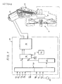
- FIG. 1 represents a control system for a clutch 11, conventional, of the friction type, inserted between a driving shaft (the vehicle crankshaft) and a driven shaft (the input shaft of a gearbox).
- the clutch is mechanically actuated by a clutch stop 12 coupled to an operating lever or fork 13 pivotally mounted.
- the fork is controlled by an electric motor 14 via an actuator associated with a spring compensator 15.
- the motor 14 is a direct current motor controlled by current pulses delivered by an electronic module 16 arranged around a microcomputer 18.
- the latter delivers a pulse signal at the input of a power stage 19 capable of applying current pulses (in one direction or the other depending on whether the is carried out a clutch switch or a clutch stroke) to the windings of the electric motor 14, these pulses having a constant amplitude and duration developed by the microcomputer 18.
- the latter receives at its inputs e 1 and e 2 signals representative of vehicle operating parameters.
- e 1 and e 2 signals representative of vehicle operating parameters.
- this singal is taken from the cursor of a potentiometer 20 coupled to the fork 13 or to the mechanical reducer linked to the motor shaft 14.
- the two signals are sent to the microcomputer 18 via an adaptation interface 22 ensuring their shaping and protection.
- Analog-digital conversion means 24 are, moreover, interposed between said interface and the input e 2.
- Other signals are sent to the microcomputer 18 via another section of the adaptation interface 22. These are respectively: S3: motor speed S4: gearbox input shaft speed S5: gearbox output shaft speed S6: actuation of the gearshift lever by the motorist.
- An alarm signal S7 can also be produced by the microcomputer 18 and sent to any signaling means of the vehicle, via the interface 22.
- the microcomputer 18 generates the engine control pulses from the parameters represented in particular by the signals S1-S6 and from a succession of pulse durations stored in a random access memory M1 which is associated with it.
- Another memory M2 called non-volatile, write-read, is connected to the microcomputer 18. Its role is to store all the information contained in the memory M1 when the motorist switches off the ignition. It may be, for example, a memory known under the name "EEPROM" in the art or a random access memory supplied by a direct link with the vehicle battery or by a small battery integrated in the system.
- the assembly formed by the microcomputer 18, the memory M valve and the analog-to-digital conversion means 24 is obtained from a component such as MOTOROLA's 6805R3, the memory M2 will be an NMC 9306E from NATIONAL SEMICONDUCTOR.
- the operation is as follows.
- the microcomputer is capable of generating all the sequences of control pulses corresponding to the different configurations of the clutch and disengage operations.
- the rapid maneuvers corresponding to speed changes or to a sudden start give rise to the development of pulse trains whose durations result essentially from the analysis of the signal S signal, that is to say more precisely from the comparison between the actual position of the actuator and that which should result from the number of pulses already applied.
- the microcomputer 19 commands an increase in the duration of the pulses applied. If, on the contrary, the actuator is "ahead", the microcomputer commands a reduction in the duration of these pulses, or even their outright elimination in certain places of the race.
- the system memorizes two groups of predetermined durations which correspond to a clutch and a disengage at so-called normal speed (i.e. - say neither especially fast nor specially slow), in other words, a forward and a backward stroke of the actuator during which its speed remains below a certain value for which the displacement increments of said actuator corresponding to the pulses can be distinguished.
- the actuator stroke is, in this exemplary embodiment, divided into four ranges to which a predetermined number n of pulses of constant duration are made to correspond, the duration being specific to the range.
- the amplitude of the pulses is also kept constant.
- the clutch or disengage stroke will be entirely traversed by the application of 32 successive pulses of only four different durations corresponding to the different ranges.
- the random access memory M1 thus has to memorize only four predetermined durations for a outward journey and four predetermined durations for a return journey, ie a total of only eight values.
- the predetermined duration associated with each elementary movement is constant in each range. For so-called slow clutch engagement and disengagement operations, these values are simply read by the microcomputer 18 and are used directly for developing the trains of pulses transmitted and amplified by the power stage 19.
- the predetermined durations contained in the memory M1 are possibly corrected if the successive measured positions of the actuator (the signal S1) do not correspond to the expected positions, after each pulse or after a given group of such impulses.
- This updating of the memory M1 makes it possible to take account of the slow evolution of the torque seen by the engine and therefore of the mechanical characteristics of the clutch device, in particular the wear of the clutch.
- the system can "educate" itself by means of a limited number of clutch and declutching operations if the durations recorded in the memory are relatively far from the durations required to obtain the desired displacement . This can be the case in particular when the clutch is put into service for the first time.
- the microcomputer controls the transfer of all the values written in the memory M1 to the non-volatile memory M2. These values serve as references for the next start.
- An additional signal S8 is therefore provided which is representative of the temperature outside the vehicle. when starting the vehicle, the computer will correct the data contained in the non-volatile memory as a function of this signal S8 before copying them into the memory M1.
- FIG. 2 illustrates the force characteristic (E) which it is necessary to apply to the clutch during the actuation stroke (C A ), when it is new (curve A) and when it is used (curve B).
- Curve C shows that the characteristic of the spring compensator associated with the actuator is chosen to roughly compensate for that of a clutch in the middle of its service life.
- the torque C p developed by the electric motor 14 throughout a double clutch and declutching stroke is in accordance with FIG. 3 when the clutch is new (a greater torque is required for re-clutching) and it conforms to FIG.
- the pulse corresponding to any given fraction of the declutching stroke will have a shorter duration than the pulse corresponding to the same fraction of stroke during the clutch.
- the pulse corresponding to any given fraction of the declutching stroke will have a longer duration than the pulse corresponding to the same fraction of stroke during the clutch.
- the microcomputer is programmed to periodically compare two by two (in the memory M1 or even in the memory M2, before starting for example) the predetermined durations recorded for the same portion of the actuator stroke, at the clutch and the disengage .
- a signaling means can be activated. More generally, an excessively large difference between the predetermined durations compared will always be representative of a defect. In particular, in addition to wear, too large a deviation in the same direction could mean a rupture of the compensator spring. Too large a deviation in the other direction could mean a rupture of the clutch diaphragm.
Landscapes
- Engineering & Computer Science (AREA)
- Mechanical Engineering (AREA)
- General Engineering & Computer Science (AREA)
- Chemical & Material Sciences (AREA)
- Combustion & Propulsion (AREA)
- Transportation (AREA)
- Physics & Mathematics (AREA)
- Automation & Control Theory (AREA)
- Electromagnetism (AREA)
- Fluid Mechanics (AREA)
- Hydraulic Clutches, Magnetic Clutches, Fluid Clutches, And Fluid Joints (AREA)
- Control Of Motors That Do Not Use Commutators (AREA)
Applications Claiming Priority (2)
| Application Number | Priority Date | Filing Date | Title |
|---|---|---|---|
| FR8700141 | 1987-01-09 | ||
| FR8700141A FR2609562B1 (fr) | 1987-01-09 | 1987-01-09 | Procede de commande d'embrayage a actionnement motorise |
Publications (2)
| Publication Number | Publication Date |
|---|---|
| EP0277049A1 true EP0277049A1 (de) | 1988-08-03 |
| EP0277049B1 EP0277049B1 (de) | 1989-12-27 |
Family
ID=9346761
Family Applications (1)
| Application Number | Title | Priority Date | Filing Date |
|---|---|---|---|
| EP88400026A Expired EP0277049B1 (de) | 1987-01-09 | 1988-01-07 | Verfahren zum Steuern einer motorbetätigten Kupplung |
Country Status (5)
| Country | Link |
|---|---|
| US (1) | US4829221A (de) |
| EP (1) | EP0277049B1 (de) |
| JP (1) | JPS63253900A (de) |
| DE (1) | DE3860015D1 (de) |
| FR (1) | FR2609562B1 (de) |
Cited By (5)
| Publication number | Priority date | Publication date | Assignee | Title |
|---|---|---|---|---|
| FR2724879A1 (fr) * | 1994-09-22 | 1996-03-29 | Fichtel & Sachs Ag | Actionneur a systeme de regulation de position d'embrayage, pour un embrayage de vehicule automobile |
| FR2729897A1 (fr) * | 1995-02-01 | 1996-08-02 | Fichtel & Sachs Ag | Embrayage a friction comprenant un actionneur |
| WO1999058868A1 (fr) * | 1998-05-13 | 1999-11-18 | Valeo | Embrayage a friction a dispositif de rattrapage d'usure, notamment pour vehicule automobile |
| NL1010512C2 (nl) * | 1998-11-09 | 2000-05-10 | Neopost Bv | Elektromagnetisch bedieningssysteem en werkwijze voor het elektromagnetisch besturen van een bedieningsorgaan. |
| EP1319857A1 (de) * | 2001-12-17 | 2003-06-18 | Renault s.a.s. | Kupplungsabnutzungsdiagnosesystem eines Kraftfahrzeuges |
Families Citing this family (28)
| Publication number | Priority date | Publication date | Assignee | Title |
|---|---|---|---|---|
| FR2641836B1 (fr) * | 1989-01-18 | 1991-03-22 | Valeo | Dispositif de commande pour moyen d'accouplement, par exemple embrayage |
| FR2652547B1 (fr) * | 1989-09-29 | 1995-06-02 | Valeo | Timonerie de transmission de forces pour vehicules automobiles. |
| FR2663887B1 (fr) * | 1990-06-29 | 1995-06-30 | Valeo | Actionneur, notamment pour la commande d'un embrayage de vehicule automobile. |
| US5592058A (en) * | 1992-05-27 | 1997-01-07 | General Electric Company | Control system and methods for a multiparameter electronically commutated motor |
| US5353902A (en) * | 1992-06-16 | 1994-10-11 | Dana Corporation | Electric actuator assembly for clutch |
| FR2697213B1 (fr) * | 1992-10-26 | 1994-12-02 | Valeo | Procédé de protection contre les démarrages intempestifs d'un véhicule. |
| DE4324810A1 (de) * | 1993-07-23 | 1995-01-26 | Zahnradfabrik Friedrichshafen | Regelverfahren für ein stufenloses Umschlingungsgetriebe |
| DE19504935A1 (de) * | 1994-02-23 | 1995-08-24 | Luk Getriebe Systeme Gmbh | Verfahren zum Steuern eines Drehmomenten-Übertragungssystems |
| DE4433826C2 (de) * | 1994-09-22 | 1996-10-02 | Fichtel & Sachs Ag | Stelleinrichtung mit einem Gehäuse |
| DE19549626A1 (de) * | 1995-02-01 | 1999-09-09 | Mannesmann Sachs Ag | Betätigungsvorrichtung, insbesondere für ein Fahrzeug |
| DE19540921A1 (de) * | 1995-11-03 | 1997-05-07 | Bosch Gmbh Robert | System zur Steuerung einer Servokupplung |
| NO314174B1 (no) * | 1995-12-18 | 2003-02-10 | Luk Getriebe Systeme Gmbh | Motorkjöretöy |
| DE19700935A1 (de) * | 1996-01-31 | 1997-08-07 | Luk Getriebe Systeme Gmbh | Vorrichtung zur Betätigung eines Aggregates im Antriebsstrang eines Kraftfahrzeuges |
| DE19639376C1 (de) * | 1996-09-25 | 1998-03-26 | Daimler Benz Ag | Automatisch gesteuerte Kupplung |
| DE19850977B4 (de) * | 1997-11-19 | 2007-01-25 | Luk Gs Verwaltungs Kg | Verfahren zum Prüfen einer automatisierten Kupplungseinrichtung |
| GB2375155B (en) * | 1997-11-29 | 2002-12-31 | Luk Getriebe Systeme Gmbh | Clutch |
| DE19853333A1 (de) * | 1997-11-29 | 1999-06-02 | Luk Getriebe Systeme Gmbh | Kupplung |
| GB9803051D0 (en) * | 1998-02-13 | 1998-04-08 | Ap Kongsberg Ltd | Clutch actuators |
| FI116338B (fi) * | 1998-07-23 | 2005-10-31 | Abb Oy | Järjestely ja menetelmä sähkökoneessa |
| FR2790806B1 (fr) | 1999-03-08 | 2001-04-27 | Valeo | Dispositif de commande pour moyen d'accouplement avec moderation d'effort variable |
| JP5041624B2 (ja) * | 2000-11-21 | 2012-10-03 | アイシン精機株式会社 | クラッチの制御装置 |
| DE10355253B4 (de) | 2002-11-28 | 2018-11-22 | Schaeffler Technologies AG & Co. KG | Reibungskupplungseinrichtung und Verfahren zur Diagnose einer Kupplungseinrichtung |
| EP1775449B1 (de) * | 2005-10-11 | 2009-06-17 | LuK Lamellen und Kupplungsbau Beteiligungs KG | Antriebsstrang für ein Kraftfahrzeug und Verfahren zum Betreiben eines solchen Antriebsstrangs |
| JP5089056B2 (ja) * | 2006-02-24 | 2012-12-05 | ヤマハ発動機株式会社 | クラッチ異常検出装置、自動クラッチ装置および鞍乗型車両 |
| CN101038033A (zh) * | 2006-03-17 | 2007-09-19 | 比亚迪股份有限公司 | 换挡动力补偿装置 |
| DE102009037400B4 (de) | 2009-08-13 | 2017-07-06 | Audi Ag | Betriebs-und Diagnoseverfahren für eine elektromotorische Antriebsvorrichtung mit Rutschkupplung eines bewegbaren Fahrzeugbauteils |
| CN103080588B (zh) * | 2010-08-09 | 2016-11-09 | 舍弗勒技术股份两合公司 | 离合器和/或变速器系统,以及启动离合器和/或变速器系统的方法 |
| US9347504B2 (en) | 2013-12-20 | 2016-05-24 | Dana Automotive Systems Group, Llc | Vehicle driveline torque managing process |
Citations (5)
| Publication number | Priority date | Publication date | Assignee | Title |
|---|---|---|---|---|
| GB856060A (en) * | 1956-12-18 | 1960-12-14 | Ferodo Sa | Improvements in or relating to control circuits for electromagnetic clutches |
| FR2523743A1 (fr) * | 1982-03-18 | 1983-09-23 | Valeo | Commande pour un dispositif d'accouplement, tel qu'embrayage, variateur de vitesse, frein ou analogue |
| GB2124321A (en) * | 1982-07-22 | 1984-02-15 | Valeo | Friction clutch control compensating for wear |
| FR2540647A1 (fr) * | 1983-02-04 | 1984-08-10 | Valeo | Dispositif de pilotage automatique d'embrayage |
| FR2559106A1 (fr) * | 1984-02-07 | 1985-08-09 | Daimler Benz Ag | Dispositif permettant l'actionnement automatique de l'embrayage de vehicules au demarrage |
Family Cites Families (6)
| Publication number | Priority date | Publication date | Assignee | Title |
|---|---|---|---|---|
| JPS5779515A (en) * | 1980-10-31 | 1982-05-18 | Mitsubishi Electric Corp | Numeric controller |
| JPS58163828A (ja) * | 1982-03-19 | 1983-09-28 | Nippon Soken Inc | クラツチの摩耗検出装置 |
| JPS601450A (ja) * | 1983-06-16 | 1985-01-07 | Fujitsu Ltd | クラツチ制御装置 |
| FR2564999B1 (fr) * | 1984-05-28 | 1987-02-13 | Valeo | Commande motorisee, d'encombrement reduit, d'un dispositif d'accouplement tel qu'embrayage, variateur de vitesse, frein ou analogue |
| JPH0639215B2 (ja) * | 1985-06-14 | 1994-05-25 | マツダ株式会社 | 車両の走行制御装置 |
| FR2588629B1 (fr) * | 1985-10-11 | 1990-01-12 | Valeo | Dispositif de commande d'un moyen d'accouplement tel que par exemple un embrayage ou un variateur de vitesse ou un frein ou analogue |
-
1987
- 1987-01-09 FR FR8700141A patent/FR2609562B1/fr not_active Expired
-
1988
- 1988-01-07 US US07/141,484 patent/US4829221A/en not_active Expired - Fee Related
- 1988-01-07 DE DE8888400026T patent/DE3860015D1/de not_active Expired - Lifetime
- 1988-01-07 EP EP88400026A patent/EP0277049B1/de not_active Expired
- 1988-01-08 JP JP63002379A patent/JPS63253900A/ja active Pending
Patent Citations (5)
| Publication number | Priority date | Publication date | Assignee | Title |
|---|---|---|---|---|
| GB856060A (en) * | 1956-12-18 | 1960-12-14 | Ferodo Sa | Improvements in or relating to control circuits for electromagnetic clutches |
| FR2523743A1 (fr) * | 1982-03-18 | 1983-09-23 | Valeo | Commande pour un dispositif d'accouplement, tel qu'embrayage, variateur de vitesse, frein ou analogue |
| GB2124321A (en) * | 1982-07-22 | 1984-02-15 | Valeo | Friction clutch control compensating for wear |
| FR2540647A1 (fr) * | 1983-02-04 | 1984-08-10 | Valeo | Dispositif de pilotage automatique d'embrayage |
| FR2559106A1 (fr) * | 1984-02-07 | 1985-08-09 | Daimler Benz Ag | Dispositif permettant l'actionnement automatique de l'embrayage de vehicules au demarrage |
Cited By (8)
| Publication number | Priority date | Publication date | Assignee | Title |
|---|---|---|---|---|
| FR2724879A1 (fr) * | 1994-09-22 | 1996-03-29 | Fichtel & Sachs Ag | Actionneur a systeme de regulation de position d'embrayage, pour un embrayage de vehicule automobile |
| FR2729897A1 (fr) * | 1995-02-01 | 1996-08-02 | Fichtel & Sachs Ag | Embrayage a friction comprenant un actionneur |
| WO1999058868A1 (fr) * | 1998-05-13 | 1999-11-18 | Valeo | Embrayage a friction a dispositif de rattrapage d'usure, notamment pour vehicule automobile |
| FR2778707A1 (fr) * | 1998-05-13 | 1999-11-19 | Valeo | Embrayage a friction a dispositif de rattrapage d'usure, notamment pour vehicule automobile |
| NL1010512C2 (nl) * | 1998-11-09 | 2000-05-10 | Neopost Bv | Elektromagnetisch bedieningssysteem en werkwijze voor het elektromagnetisch besturen van een bedieningsorgaan. |
| EP1001183A1 (de) * | 1998-11-09 | 2000-05-17 | Neopost B.V. | Steuerungssystem- und Verfahren zur elektromagnetischen Betätigung eines Steuerorgans |
| EP1319857A1 (de) * | 2001-12-17 | 2003-06-18 | Renault s.a.s. | Kupplungsabnutzungsdiagnosesystem eines Kraftfahrzeuges |
| FR2833667A1 (fr) * | 2001-12-17 | 2003-06-20 | Renault | Systeme de diagnostic de l'usure de l'embrayage d'un vehicule automobile |
Also Published As
| Publication number | Publication date |
|---|---|
| EP0277049B1 (de) | 1989-12-27 |
| FR2609562B1 (fr) | 1989-05-19 |
| FR2609562A1 (fr) | 1988-07-15 |
| US4829221A (en) | 1989-05-09 |
| DE3860015D1 (de) | 1990-02-01 |
| JPS63253900A (ja) | 1988-10-20 |
Similar Documents
| Publication | Publication Date | Title |
|---|---|---|
| EP0277049B1 (de) | Verfahren zum Steuern einer motorbetätigten Kupplung | |
| FR2572032A1 (fr) | Dispositif d'embrayage pour un vehicule a moteur | |
| FR2508104A1 (fr) | Dispositif de commande pour un moteur pouvant fonctionner avec deux carburants gaz/gazole | |
| FR2771785A1 (fr) | Procede et dispositif pour identifier des fonctionnements d'un embrayage de vehicule automobile | |
| EP0618998B1 (de) | Steuerungssystem für eine brennkkraftmaschine mit motorisiertem drosselklappgehäuse | |
| EP0401079A1 (de) | Elektromechanische Steuervorrichtung,verwendbar für die Steuerung eines Fahrzeugs | |
| FR2764249A1 (fr) | Dispositif pour commander un etat d'enclenchement | |
| EP0819227A2 (de) | Verfahren zur steuerung eines halbautomatischebn getriebes beim stillstand eines fahrzeuges | |
| EP0420736A1 (de) | Gestänge zur Kraftübertragung für Kraftfahrzeuge | |
| FR2607298A1 (fr) | Procede de lecture d'une scene mobile enregistree, notamment sur videodisque et application a des simulateurs de conduite | |
| EP0522924B1 (de) | Drehantrieb zur Erzeugung eines durch adaptierbare Steuerkennlinien veränderbaren Drehmoments am Steuerrad eines Steuersystems | |
| WO1998018119A1 (fr) | Console de commande | |
| FR2718102A1 (fr) | Procédé pour réaliser une loi d'effort antagoniste au mouvement d'un levier de commande de vol et son application au vérin de trim. | |
| EP1792106B1 (de) | Verfahren zur steuerung im multibedienungsmodus eines automatikgetriebes für ein kraftfahrzeug, besonders für leerlaufbetrieb mit nichtangezogener bremse und dazugehörige vorrichtung | |
| FR2928186A1 (fr) | Procede de determination automatique du point de lechage d'un embrayage par apprentissage | |
| WO2005119033A2 (fr) | Procede de controle d'une consigne de couple a appliquer aux roues d'une transmission automatisee pour vehicule automobile et dispositif correspondant. | |
| FR2793920A1 (fr) | Dispositif de diagnostic a base de microprocesseur, en particulier pour vehicules automobiles | |
| EP1319857A1 (de) | Kupplungsabnutzungsdiagnosesystem eines Kraftfahrzeuges | |
| FR2786284A1 (fr) | Procede de controle de mouvement d'un element servocommande | |
| EP0918266A1 (de) | Steuergerät für motorisierte Sonnenschutzvorrichtung | |
| FR2794833A1 (fr) | Procede de mise en oeuvre d'un changement de vitesse et changement de vitesse | |
| EP0420737B1 (de) | Gestänge zur Kraftübertragung für Kraftfahrzeuge | |
| EP1791715B1 (de) | Verfahren zur steuerung des mehrbetriebsmodus eines automatikgetriebes für ein kraftfahrzeug, im besonderen für leerlaufbetrieb mit angezogener bremse und dazugehörige vorrichtung | |
| EP1369281A1 (de) | Vorrichtung und Verfahren zum Ab- und Zuschalten der Brennkraftmaschine eines seriellen Hybridfahrzeugs | |
| FR2920848A1 (fr) | Procede et dispositif de commande d'un embrayage par determination du couple transmis pour un vehicule automobile. |
Legal Events
| Date | Code | Title | Description |
|---|---|---|---|
| PUAI | Public reference made under article 153(3) epc to a published international application that has entered the european phase |
Free format text: ORIGINAL CODE: 0009012 |
|
| AK | Designated contracting states |
Kind code of ref document: A1 Designated state(s): DE IT |
|
| 17P | Request for examination filed |
Effective date: 19880723 |
|
| 17Q | First examination report despatched |
Effective date: 19890518 |
|
| GRAA | (expected) grant |
Free format text: ORIGINAL CODE: 0009210 |
|
| AK | Designated contracting states |
Kind code of ref document: B1 Designated state(s): DE IT |
|
| REF | Corresponds to: |
Ref document number: 3860015 Country of ref document: DE Date of ref document: 19900201 |
|
| ITF | It: translation for a ep patent filed | ||
| PLBI | Opposition filed |
Free format text: ORIGINAL CODE: 0009260 |
|
| 26 | Opposition filed |
Opponent name: FICHTEL & SACHS AG Effective date: 19900927 |
|
| PLBN | Opposition rejected |
Free format text: ORIGINAL CODE: 0009273 |
|
| STAA | Information on the status of an ep patent application or granted ep patent |
Free format text: STATUS: OPPOSITION REJECTED |
|
| 27O | Opposition rejected |
Effective date: 19920306 |
|
| ITTA | It: last paid annual fee | ||
| PGFP | Annual fee paid to national office [announced via postgrant information from national office to epo] |
Ref country code: DE Payment date: 20020115 Year of fee payment: 15 |
|
| PG25 | Lapsed in a contracting state [announced via postgrant information from national office to epo] |
Ref country code: DE Free format text: LAPSE BECAUSE OF NON-PAYMENT OF DUE FEES Effective date: 20030801 |
|
| PG25 | Lapsed in a contracting state [announced via postgrant information from national office to epo] |
Ref country code: IT Free format text: LAPSE BECAUSE OF NON-PAYMENT OF DUE FEES;WARNING: LAPSES OF ITALIAN PATENTS WITH EFFECTIVE DATE BEFORE 2007 MAY HAVE OCCURRED AT ANY TIME BEFORE 2007. THE CORRECT EFFECTIVE DATE MAY BE DIFFERENT FROM THE ONE RECORDED. Effective date: 20050107 |