EP0277300A1 - Dispositif d'épuration et neutralisation des résidus de chaufferies - Google Patents
Dispositif d'épuration et neutralisation des résidus de chaufferies Download PDFInfo
- Publication number
- EP0277300A1 EP0277300A1 EP87117423A EP87117423A EP0277300A1 EP 0277300 A1 EP0277300 A1 EP 0277300A1 EP 87117423 A EP87117423 A EP 87117423A EP 87117423 A EP87117423 A EP 87117423A EP 0277300 A1 EP0277300 A1 EP 0277300A1
- Authority
- EP
- European Patent Office
- Prior art keywords
- container
- filter
- water tank
- activated carbon
- flue gas
- Prior art date
- Legal status (The legal status is an assumption and is not a legal conclusion. Google has not performed a legal analysis and makes no representation as to the accuracy of the status listed.)
- Granted
Links
- 238000006386 neutralization reaction Methods 0.000 title description 2
- 238000000746 purification Methods 0.000 title 1
- XLYOFNOQVPJJNP-UHFFFAOYSA-N water Substances O XLYOFNOQVPJJNP-UHFFFAOYSA-N 0.000 claims abstract description 99
- OKTJSMMVPCPJKN-UHFFFAOYSA-N Carbon Chemical compound [C] OKTJSMMVPCPJKN-UHFFFAOYSA-N 0.000 claims abstract description 46
- 239000007788 liquid Substances 0.000 claims abstract description 27
- 239000000446 fuel Substances 0.000 claims abstract description 4
- 230000003472 neutralizing effect Effects 0.000 claims abstract description 3
- 239000003546 flue gas Substances 0.000 claims description 46
- UGFAIRIUMAVXCW-UHFFFAOYSA-N Carbon monoxide Chemical compound [O+]#[C-] UGFAIRIUMAVXCW-UHFFFAOYSA-N 0.000 claims description 38
- 239000008187 granular material Substances 0.000 claims description 28
- 239000004579 marble Substances 0.000 claims description 28
- 238000004140 cleaning Methods 0.000 claims description 10
- 229920005830 Polyurethane Foam Polymers 0.000 claims description 9
- 239000011496 polyurethane foam Substances 0.000 claims description 9
- 239000000919 ceramic Substances 0.000 claims description 5
- 239000013505 freshwater Substances 0.000 claims description 5
- 239000002984 plastic foam Substances 0.000 claims description 5
- 239000000945 filler Substances 0.000 claims description 4
- 238000005406 washing Methods 0.000 claims description 3
- 239000002253 acid Substances 0.000 claims description 2
- 238000003302 UV-light treatment Methods 0.000 claims 1
- 238000010304 firing Methods 0.000 claims 1
- 239000011810 insulating material Substances 0.000 claims 1
- 238000010521 absorption reaction Methods 0.000 abstract 1
- 238000001914 filtration Methods 0.000 abstract 1
- 239000010865 sewage Substances 0.000 description 9
- 238000010438 heat treatment Methods 0.000 description 6
- 230000002378 acidificating effect Effects 0.000 description 5
- 239000007787 solid Substances 0.000 description 5
- 229930195733 hydrocarbon Natural products 0.000 description 4
- 150000002430 hydrocarbons Chemical class 0.000 description 4
- 239000002245 particle Substances 0.000 description 4
- 239000002250 absorbent Substances 0.000 description 3
- 230000002745 absorbent Effects 0.000 description 3
- 238000006477 desulfuration reaction Methods 0.000 description 3
- 230000023556 desulfurization Effects 0.000 description 3
- 239000003344 environmental pollutant Substances 0.000 description 3
- 231100000719 pollutant Toxicity 0.000 description 3
- RAHZWNYVWXNFOC-UHFFFAOYSA-N Sulphur dioxide Chemical compound O=S=O RAHZWNYVWXNFOC-UHFFFAOYSA-N 0.000 description 2
- 238000002485 combustion reaction Methods 0.000 description 2
- 230000003584 silencer Effects 0.000 description 2
- 239000010802 sludge Substances 0.000 description 2
- 239000004071 soot Substances 0.000 description 2
- 239000000126 substance Substances 0.000 description 2
- XTQHKBHJIVJGKJ-UHFFFAOYSA-N sulfur monoxide Chemical class S=O XTQHKBHJIVJGKJ-UHFFFAOYSA-N 0.000 description 2
- 229910052815 sulfur oxide Inorganic materials 0.000 description 2
- 229910000831 Steel Inorganic materials 0.000 description 1
- NINIDFKCEFEMDL-UHFFFAOYSA-N Sulfur Chemical compound [S] NINIDFKCEFEMDL-UHFFFAOYSA-N 0.000 description 1
- 239000002956 ash Substances 0.000 description 1
- 238000011001 backwashing Methods 0.000 description 1
- 239000012671 ceramic insulating material Substances 0.000 description 1
- 238000005352 clarification Methods 0.000 description 1
- 230000007797 corrosion Effects 0.000 description 1
- 238000005260 corrosion Methods 0.000 description 1
- 239000003651 drinking water Substances 0.000 description 1
- 235000020188 drinking water Nutrition 0.000 description 1
- 238000005108 dry cleaning Methods 0.000 description 1
- 239000000428 dust Substances 0.000 description 1
- 238000003912 environmental pollution Methods 0.000 description 1
- 239000000463 material Substances 0.000 description 1
- 238000012856 packing Methods 0.000 description 1
- 230000000149 penetrating effect Effects 0.000 description 1
- 229920003023 plastic Polymers 0.000 description 1
- 239000004033 plastic Substances 0.000 description 1
- 239000010959 steel Substances 0.000 description 1
- 229910052717 sulfur Inorganic materials 0.000 description 1
- 239000011593 sulfur Substances 0.000 description 1
- 239000002351 wastewater Substances 0.000 description 1
Images


Classifications
-
- C—CHEMISTRY; METALLURGY
- C02—TREATMENT OF WATER, WASTE WATER, SEWAGE, OR SLUDGE
- C02F—TREATMENT OF WATER, WASTE WATER, SEWAGE, OR SLUDGE
- C02F1/00—Treatment of water, waste water, or sewage
- C02F1/28—Treatment of water, waste water, or sewage by sorption
-
- B—PERFORMING OPERATIONS; TRANSPORTING
- B01—PHYSICAL OR CHEMICAL PROCESSES OR APPARATUS IN GENERAL
- B01D—SEPARATION
- B01D17/00—Separation of liquids, not provided for elsewhere, e.g. by thermal diffusion
- B01D17/02—Separation of non-miscible liquids
- B01D17/0202—Separation of non-miscible liquids by ab- or adsorption
-
- B—PERFORMING OPERATIONS; TRANSPORTING
- B01—PHYSICAL OR CHEMICAL PROCESSES OR APPARATUS IN GENERAL
- B01D—SEPARATION
- B01D17/00—Separation of liquids, not provided for elsewhere, e.g. by thermal diffusion
- B01D17/02—Separation of non-miscible liquids
- B01D17/0208—Separation of non-miscible liquids by sedimentation
-
- B—PERFORMING OPERATIONS; TRANSPORTING
- B01—PHYSICAL OR CHEMICAL PROCESSES OR APPARATUS IN GENERAL
- B01D—SEPARATION
- B01D17/00—Separation of liquids, not provided for elsewhere, e.g. by thermal diffusion
- B01D17/08—Thickening liquid suspensions by filtration
- B01D17/10—Thickening liquid suspensions by filtration with stationary filtering elements
-
- B—PERFORMING OPERATIONS; TRANSPORTING
- B01—PHYSICAL OR CHEMICAL PROCESSES OR APPARATUS IN GENERAL
- B01D—SEPARATION
- B01D53/00—Separation of gases or vapours; Recovering vapours of volatile solvents from gases; Chemical or biological purification of waste gases, e.g. engine exhaust gases, smoke, fumes, flue gases, aerosols
- B01D53/02—Separation of gases or vapours; Recovering vapours of volatile solvents from gases; Chemical or biological purification of waste gases, e.g. engine exhaust gases, smoke, fumes, flue gases, aerosols by adsorption, e.g. preparative gas chromatography
-
- C—CHEMISTRY; METALLURGY
- C02—TREATMENT OF WATER, WASTE WATER, SEWAGE, OR SLUDGE
- C02F—TREATMENT OF WATER, WASTE WATER, SEWAGE, OR SLUDGE
- C02F1/00—Treatment of water, waste water, or sewage
- C02F1/28—Treatment of water, waste water, or sewage by sorption
- C02F1/281—Treatment of water, waste water, or sewage by sorption using inorganic sorbents
-
- C—CHEMISTRY; METALLURGY
- C02—TREATMENT OF WATER, WASTE WATER, SEWAGE, OR SLUDGE
- C02F—TREATMENT OF WATER, WASTE WATER, SEWAGE, OR SLUDGE
- C02F1/00—Treatment of water, waste water, or sewage
- C02F1/28—Treatment of water, waste water, or sewage by sorption
- C02F1/283—Treatment of water, waste water, or sewage by sorption using coal, charred products, or inorganic mixtures containing them
-
- C—CHEMISTRY; METALLURGY
- C02—TREATMENT OF WATER, WASTE WATER, SEWAGE, OR SLUDGE
- C02F—TREATMENT OF WATER, WASTE WATER, SEWAGE, OR SLUDGE
- C02F1/00—Treatment of water, waste water, or sewage
- C02F1/28—Treatment of water, waste water, or sewage by sorption
- C02F1/285—Treatment of water, waste water, or sewage by sorption using synthetic organic sorbents
-
- C—CHEMISTRY; METALLURGY
- C02—TREATMENT OF WATER, WASTE WATER, SEWAGE, OR SLUDGE
- C02F—TREATMENT OF WATER, WASTE WATER, SEWAGE, OR SLUDGE
- C02F1/00—Treatment of water, waste water, or sewage
- C02F1/66—Treatment of water, waste water, or sewage by neutralisation; pH adjustment
-
- C—CHEMISTRY; METALLURGY
- C02—TREATMENT OF WATER, WASTE WATER, SEWAGE, OR SLUDGE
- C02F—TREATMENT OF WATER, WASTE WATER, SEWAGE, OR SLUDGE
- C02F2101/00—Nature of the contaminant
- C02F2101/30—Organic compounds
- C02F2101/32—Hydrocarbons, e.g. oil
-
- C—CHEMISTRY; METALLURGY
- C02—TREATMENT OF WATER, WASTE WATER, SEWAGE, OR SLUDGE
- C02F—TREATMENT OF WATER, WASTE WATER, SEWAGE, OR SLUDGE
- C02F2103/00—Nature of the water, waste water, sewage or sludge to be treated
- C02F2103/18—Nature of the water, waste water, sewage or sludge to be treated from the purification of gaseous effluents
-
- Y—GENERAL TAGGING OF NEW TECHNOLOGICAL DEVELOPMENTS; GENERAL TAGGING OF CROSS-SECTIONAL TECHNOLOGIES SPANNING OVER SEVERAL SECTIONS OF THE IPC; TECHNICAL SUBJECTS COVERED BY FORMER USPC CROSS-REFERENCE ART COLLECTIONS [XRACs] AND DIGESTS
- Y10—TECHNICAL SUBJECTS COVERED BY FORMER USPC
- Y10S—TECHNICAL SUBJECTS COVERED BY FORMER USPC CROSS-REFERENCE ART COLLECTIONS [XRACs] AND DIGESTS
- Y10S261/00—Gas and liquid contact apparatus
- Y10S261/09—Furnace gas scrubbers
Definitions
- the invention relates to a device for cleaning and neutralizing residues from furnaces with liquid or gaseous fuels, in particular from condensing boilers.
- heating boilers which are referred to as condensing boilers
- the flue gases of the furnace are cooled below the dew point, so that the water vapor contained in the flue gases condenses and is deposited together with the pollutants and other combustion residues contained in the flue gases.
- This condensate contains sulfur oxides due to the sulfur present in the fossil liquid or gaseous fuels and is therefore very acidic.
- the invention has for its object to collect, clean and neutralize the residues from the furnace as completely as possible.
- the device according to the invention works in two stages. First of all, the condensate accumulating in the heating boiler or the cleaning water accumulating when the heating boiler is wet cleaned is led into a settling tank via a water reservoir. The water is in the settling tank so that the heavier particles contained in the water, such as ash and soot, can settle. The unburned oil droplets contained in the water collect on the surface. The oil droplets are absorbed by oil suction bodies, which consist of a material known per se, as described, for example, in DE 23 06 916 C3. The oil absorbent bodies can float as cubes or balls on the surface of the water in the settling tank or can be introduced into the water, in particular in its upper layer, as a plate or other shaped body.
- the sludge of the heavier particles which settles on the bottom of the settling container can preferably be removed via an emptying opening.
- the water which has been largely cleaned of oil and solid particles in this way, enters through a filter a clean water tank.
- the filter is preferably designed as a filter plate that separates the settling tank and the pure water tank from one another.
- the filter plate preferably consists of a water-permeable rigid plastic foam, in particular of an open-cell polyurethane foam. This filter allows the water with the dissolved substances contained therein to pass through, but reliably retains oil droplets and solids.
- the pH value of the water is raised to a permissible value, for which marble granulate is preferably used or a basic liquid is added in a metered amount.
- the water neutralized in this way flows from the pure water tank through an activated carbon filter into the sewage system. Essentially, the dissolved and undissolved hydrocarbons still contained in the water are absorbed. The water entering the sewage system is therefore of drinking water quality.
- a float switch is preferably provided in the settling tank, which switches off the burner of the furnace if the liquid level in the settling tank rises too high, so that the device cannot absorb any further condensate.
- the neutralized water in the pure water tank can also be pumped off and fed to a flue gas scrubber for flue gas desulfurization.
- the wash water which is acidic again due to the flue gas desulfurization, is returned to the cleaning device.
- a float switch is also provided in the clean water tank, which controls a fresh water supply and ensures a sufficient water level in the pure water tank.
- the pH is raised by two separate marble granulate containers.
- the water is pumped out to the flue gas scrubber via a first marble granulate container with a high water throughput. Due to the high water throughput, there is no complete neutralization, but the water supplied to the flue gas scrubber still has a pH of approx. 5 to 6. This slightly acidic wash water is suitable for operating the flue gas scrubber.
- the strongly acidic wash water emerging from the flue gas scrubber is returned to the cleaning device.
- the water from the pure water tank is led into the sewage system via the activated carbon filter via a second marble granulate tank with low water throughput. Only the overflow amount of water from the pure water tank, which is generated by the constantly occurring condensate, flows through the second marble granulate tank and the activated carbon filter. Only this much lower overflow quantity of e.g. 0.6 kg per liter of heating oil loads the activated carbon filter so that it only needs to be replaced rarely. The small overflow quantity results in a low water throughput through the marble granulate, so that a longer contact time between the water and the marble granulate is possible and the pH is raised to 6.5 to 7.0. The water can thus be safely discharged into the sewage system.
- An extremely simply constructed flue gas scrubber can be operated with the wash water obtained according to the invention.
- This consists of a gas-permeable grid inserted into a pipe through which the flue gases flow, on which ceramic fillers are layered, through which the washing water is trickled.
- the flue gas scrubber can also be designed as a silencer.
- the device has a cuboid-shaped container 10 which is separated by a filter plate 12 into a settling container 14 and a pure water container 16.
- the filter plate 12 consists of an open-cell polyurethane foam which is permeable to water, but does not allow oil droplets and solid components to pass through.
- An inlet 18 leads into the settling tank 14, through which the condensate of the heating boiler is fed via a water reservoir and the cleaning water for wet boiler cleaning.
- oil suction bodies 22 are provided which float on the surface of the liquid in the settling tank.
- the oil absorbent bodies 22 can float freely on the surface of the liquid as cubes or can be combined in the form of smaller bodies or balls in a mesh-shaped cushion.
- an oil-absorbing plate 23 can also be provided, which plate is attached to the filter plate 12. The oil drainage The lower end of the plate 23 protrudes into the liquid in order to absorb the oil that accumulates on the surface of the liquid, but leaves most of the surface of the filter plate 12 below the liquid level free for the passage of liquid.
- a float switch 24 which switches off the burner of the furnace when the liquid level in the settling chamber 14 rises to the upper edge of the container 10 so that the device can no longer absorb any more water.
- marble granules 26 are provided in the basket 16 for raising the pH in the pure water container 16.
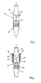
- an activated carbon filter 28 is arranged in the pure water tank 16, which is shown separately in vertical section in FIG.
- the activated carbon filter 28 consists of a can-shaped housing 30, the side walls 32 of which consist of a water-permeable rigid plastic foam, preferably also of an open-cell polyurethane foam.
- the housing 30 receives the activated carbon 34.
- the water penetrating through the side walls 32 is cleaned in the activated carbon 34, in particular the dissolved and undissolved hydrocarbons being taken up, and exits the activated carbon filter 28 and the pure water tank 16 via an outlet 36 and reaches a channel connection 38.
- the water can be drained from the container 10 via a shut-off device 40.
- the pure water tank 16 also has an outlet 42, via which water 44 can be pumped to a flue gas scrubber 46 by means of a pump.
- a further float switch 48 arranged in the pure water tank 16 controls a fresh water supply 50, so that it is ensured that there is always a sufficient water supply for the flue gas scrubber 46 in the pure water tank 16.
- the filter plate 12, the oil suction body or the oil suction plate 23, the marble granulate 26 and the activated carbon filter 28 are of course interchangeable, so that they can be replaced if necessary.
- two containers 52 and 54 filled with marble granulate 26 are arranged in the pure water container 16.
- the e.g. Cylindrical containers 52 and 54 have inlet openings 56 for the liquid in their upper region below the liquid level determined by the outlet 36.
- the outlet 42 opens, through which the water is discharged to the flue gas scrubber 46 by means of the pump 44.
- a filter layer 58 e.g. made of water-permeable rigid plastic foam, e.g. made of open-cell polyurethane foam, prevents the marble granules 26 from entering the outlet 42.
- the second container 54 has a smaller cross-section and is connected via a tube opening near the floor to a housing 30 which receives the activated carbon filter 28 sealed off by the side walls 32.
- the outlet 36 emerges from the housing 30 and leads to the vented channel connection 38.
- the water entering the clean water tank 16 through the filter plate 12 passes through the inlet openings 56 into the marble granulate tank 52 and is conveyed to the flue gas scrubber 46 by means of the pump 44.
- the water flows from the flue gas scrubber 46 back to the inlet 18 of the settling tank.
- the water pumped through the flue gas scrubber 46 by means of the pump 44 at a relatively high throughput of approximately 300 liters / hour is thus completely returned to the device, so that the liquid level in the device practically does not change as a result.
- the washing water again absorbs sulfur oxides, so that it flows back into the settling tank and the pure water tank 16 at a much lower pH.
- the acidic liquid in the pure water container 16 also passes through the inlet opening 56 into the marble granulate container 54.
- the liquid level in the pure water container 16 rises above the height of the outlet 36, the water flows through the marble granulate 26 of the container 54 and the activated carbon filter 28 via the outlet 36 into the sewage system. Since the container 54 has a smaller diameter and the liquid is not pumped out through the drain 36, there is a longer contact time between the water and the marble granulate 26 in the container 54, so that the pH of the liquid is increased more and the water from the outlet 36 with a pH of about 6.5 to 7.0 into the sewage system.
- a flue gas scrubber 46 as is preferably used, is shown in FIG. 4.
- the flue gas scrubber 46 has a tube 60 through which the flue gases are passed vertically from bottom to top.
- a gas-permeable horizontal grid 62 is inserted into the tube and has a mesh size of approximately 12 to 15 mm. Ceramic fillers 64 are heaped onto the grid 62 at a height of approximately 100 to 150 mm.
- the wash water is pumped through a water inlet 66 in an amount of preferably about 300 liters / hour from above over the packing 64 and trickled into this.
- An additional fresh water inlet 68 comes into operation when the amount of condensate is insufficient to supply enough wash water via the pump 44.
- the flue gas scrubber is used to wash out sulfur dioxide, Soot particles, dust, ash and other oil-specific residues from the flue gases.
- the wash water emerging from the flue gas scrubber 46 at the bottom is fed back into the device via the inlet 18.
- the heaped-up ceramic fillers 64 produce only a low flow resistance for the flue gases, which produces a pressure drop of approximately 1 to 4 mm WS. This is favored by the fact that the tube 60 is expanded to a diameter of 150 to 180 mm compared to the flue gas tube with a diameter of about 80 to 100 mm.
- the upper end of the flue gas scrubber 46 is connected gas-tight to the flue gas pipe leading to the chimney.
- the tube 60 of the flue gas scrubber 46 is enclosed in its upper region by a corrosion-resistant tube 70 of larger diameter, which is tightly connected to the tube 60 at the bottom.
- the pipe 60 of the flue gas scrubber is provided with bores 72 in the area of the outer pipe 70.
- the space between the tubes 60 and 70 is stuffed with an acid-resistant, preferably ceramic insulating material 74.
- the flue gas scrubber 46 also acts as a silencer.
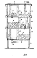
- Figure 6 shows an embodiment of the device that has proven itself in practice and is characterized by a particularly simple and compact structure.
- a frame consisting of a frame 76 and four feet 78 made of square tubular steel, carries three stacked cuboid plastic containers 80, 82 and 84.
- the inlet 18 leads vertically from above into the upper container 80, which is closed by a lid 86
- the upper container 80 serves as a settling container 14 and receives the oil absorbing bodies 22.
- a cylindrical insert 88 is inserted into the container 80, which corresponds to the filter plate 12 of the previous embodiments and how it consists of an open-cell polyurethane foam.
- the insert 88 encloses an overflow 90 leading to the middle tank 82.
- the condensate or cleaning water supplied via the inlet 18 is in the upper tank 80 at the height determined by the overflow 90. Solid components settle in the upper container 80.
- Oil components are absorbed by the oil absorbent body 22. Filtered through the insert 88, the liquid reaches the middle container 82 via the overflow 90.
- the middle container 82 is filled with the marble granulate 26.
- the middle container 82 also has an insert 88 made of open-cell polyurethane foam, which encloses an overflow 90.
- the liquid coming from the upper container 80 is in the middle container 82 at the height determined by the overflow 90 and is neutralized by the marble granulate 26.
- the filtered and neutrasilized liquid reaches the lower container 84, which is filled with the activated carbon 34.
- a cylindrical insert 88 made of polyurethane foam is also inserted in the lower container 84 and surrounds the outlet 36. In the lower container 84, the organic substances still present in the cleaned and neutralized condensate, in particular hydrocarbons, are bound.
- a flue gas scrubber can also be connected if necessary.
- the connecting line for the flue gas scrubber would be arranged on the middle container 82 below the height of the overflow 90, so that only a small excess of the condensate reaches the outlet 36 via the lower container 84.
- a hose or pipe with outlet openings can optionally be provided, through which water can be introduced under pressure in order to backwash the marble granulate 26. Backwashing loosens and cleans the layer of marble granulate 26 so that the active surface of the marble granulate is regenerated.
Landscapes
- Chemical & Material Sciences (AREA)
- Chemical Kinetics & Catalysis (AREA)
- Thermal Sciences (AREA)
- Physics & Mathematics (AREA)
- Engineering & Computer Science (AREA)
- Water Supply & Treatment (AREA)
- Hydrology & Water Resources (AREA)
- Environmental & Geological Engineering (AREA)
- Life Sciences & Earth Sciences (AREA)
- Organic Chemistry (AREA)
- Analytical Chemistry (AREA)
- General Chemical & Material Sciences (AREA)
- Oil, Petroleum & Natural Gas (AREA)
- Treating Waste Gases (AREA)
- Separation Of Particles Using Liquids (AREA)
- Water Treatment By Sorption (AREA)
- Cleaning Or Drying Semiconductors (AREA)
- Organic Low-Molecular-Weight Compounds And Preparation Thereof (AREA)
Priority Applications (1)
| Application Number | Priority Date | Filing Date | Title |
|---|---|---|---|
| AT87117423T ATE57897T1 (de) | 1987-01-22 | 1987-11-26 | Vorrichtung zur reinigung und neutralisation von rueckstaenden aus feuerungen. |
Applications Claiming Priority (2)
| Application Number | Priority Date | Filing Date | Title |
|---|---|---|---|
| DE8700987U | 1987-01-22 | ||
| DE8700987U DE8700987U1 (de) | 1987-01-22 | 1987-01-22 | Vorrichtung zur Reinigung und Neutralisation von Rückständen aus Feuerungen |
Publications (2)
| Publication Number | Publication Date |
|---|---|
| EP0277300A1 true EP0277300A1 (fr) | 1988-08-10 |
| EP0277300B1 EP0277300B1 (fr) | 1990-10-31 |
Family
ID=6803849
Family Applications (1)
| Application Number | Title | Priority Date | Filing Date |
|---|---|---|---|
| EP87117423A Expired - Lifetime EP0277300B1 (fr) | 1987-01-22 | 1987-11-26 | Dispositif d'épuration et neutralisation des résidus de chaufferies |
Country Status (4)
| Country | Link |
|---|---|
| US (1) | US4857183A (fr) |
| EP (1) | EP0277300B1 (fr) |
| AT (1) | ATE57897T1 (fr) |
| DE (2) | DE8700987U1 (fr) |
Cited By (11)
| Publication number | Priority date | Publication date | Assignee | Title |
|---|---|---|---|---|
| DE4031339A1 (de) * | 1989-10-11 | 1991-04-18 | Mikela Haustein | Transportable aufbereitungsanlage |
| DE4217447A1 (de) * | 1992-05-26 | 1993-12-16 | Willems Germann | Feststoff-Filter |
| DE19533935A1 (de) * | 1994-09-20 | 1996-04-04 | Patrick Blaase | Filtersystem für Abwasser, insbesondere zum Einbau in einen Gully |
| DE4435304C1 (de) * | 1994-10-01 | 1996-05-15 | Joachim Dipl Ing Zeisel | Anlage für die Reinigung von Grauwasser im Rahmen eines Grauwasser-Recycling-Systems |
| FR2741283A1 (fr) * | 1995-11-22 | 1997-05-23 | Rivard Ets | Procede de lavage de sediments renfermant des composes organiques notamment des hydrocarbures ainsi que dispositif adapte a la mise en oeuvre de ce procede |
| US6645387B2 (en) | 2001-02-15 | 2003-11-11 | Evac International Oy | Separator device |
| DE102006036727A1 (de) * | 2006-08-05 | 2008-02-07 | Bomat Heiztechnik Gmbh | Vorrichtung zur Neutralisation von Kondensat aus einem Heizgerät |
| DE102006036724A1 (de) * | 2006-08-05 | 2008-02-07 | Bomat Heiztechnik Gmbh | Vorrichtung zur Neutralisation von Kondensat aus einem Heizgerät |
| EP1886975A1 (fr) * | 2006-08-10 | 2008-02-13 | Mommertz Wasser- und Wärmetechnik GmbH | Agent neutralisant |
| EP2380853A3 (fr) * | 2010-04-20 | 2013-05-22 | Bomat Heiztechnik GmbH | Dispositif de neutralisation |
| CN107473533A (zh) * | 2017-09-30 | 2017-12-15 | 盐城工学院 | 一种多级污水处理装置以及污水净化系统 |
Families Citing this family (15)
| Publication number | Priority date | Publication date | Assignee | Title |
|---|---|---|---|---|
| DE9005311U1 (de) * | 1990-05-10 | 1990-07-12 | Natuurbeton-Milieu B.V., Nederweert | Abscheider für Leichtflüssigkeiten |
| US5672323A (en) * | 1995-01-26 | 1997-09-30 | The Babcock & Wilcox Company | Activated carbon flue gas desulfurization systems for mercury removal |
| FR2767523B1 (fr) * | 1997-08-25 | 1999-10-15 | Sarl Drive | Station d'epuration a structure modulaire autoporteuse |
| DE19751934A1 (de) * | 1997-11-22 | 1999-05-27 | Babcock Anlagen Gmbh | Verfahren zum Reinigen von Rauchgas |
| DE29808579U1 (de) | 1998-05-13 | 1998-07-23 | Riedel GmbH, 79227 Schallstadt | Vorrichtung zum Reinigen von mit Verschmutzungen versetzten Flüssigkeiten |
| DE19852204A1 (de) * | 1998-11-12 | 2000-05-18 | Benkeser Michael | Flüssigkeitsabscheider |
| US6372187B1 (en) | 1998-12-07 | 2002-04-16 | Mcdermott Technology, Inc. | Alkaline sorbent injection for mercury control |
| US6284199B1 (en) | 1999-03-31 | 2001-09-04 | Mcdermott Technology, Inc. | Apparatus for control of mercury |
| US6503470B1 (en) | 1999-03-31 | 2003-01-07 | The Babcock & Wilcox Company | Use of sulfide-containing liquors for removing mercury from flue gases |
| US7037474B2 (en) * | 1999-03-31 | 2006-05-02 | The Babcock & Wilcox Company | Use of sulfide-containing liquors for removing mercury from flue gases |
| US6328939B1 (en) | 1999-03-31 | 2001-12-11 | Mcdermott Technology, Inc. | Mercury removal in utility wet scrubber using a chelating agent |
| US6855859B2 (en) * | 1999-03-31 | 2005-02-15 | The Babcock & Wilcox Company | Method for controlling elemental mercury emissions |
| DE102006035907A1 (de) * | 2006-07-31 | 2008-02-07 | Freigeber, Jürgen | Neutralisationsanlage zum Neutralisieren von belastetem Kondensat und anderen Flüssigkeiten |
| WO2009024126A1 (fr) * | 2007-08-18 | 2009-02-26 | Freigeber Juergen | Dispositif de neutralisation de condensats de combustion acides |
| GB2516885B (en) * | 2013-08-02 | 2016-04-20 | Adler And Allan Ltd | Coalescent hydrocarbon filter |
Citations (5)
| Publication number | Priority date | Publication date | Assignee | Title |
|---|---|---|---|---|
| US3471401A (en) * | 1967-09-29 | 1969-10-07 | Chevron Res | Method of removing oil from water containing suspended solids |
| DE1813886A1 (de) * | 1968-12-11 | 1970-07-16 | Steinmueller Gmbh L & C | Apparat zur kontinuierlichen Aufbereitung von Abwasser |
| DE2306916A1 (de) * | 1971-04-27 | 1974-08-15 | Puren Schaumstoff Gmbh | Verfahren zur herstellung eines festkoerpers aus oelaufsaugendem material und nach dem verfahren hergestellter festkoerper |
| GB1566172A (en) * | 1977-10-19 | 1980-04-30 | Metzeler Ab | Filter device |
| EP0162195A1 (fr) * | 1984-02-20 | 1985-11-27 | Krause, Willibald | Dispositif pour la neutralisation de condensés acides |
Family Cites Families (5)
| Publication number | Priority date | Publication date | Assignee | Title |
|---|---|---|---|---|
| US3387432A (en) * | 1966-04-22 | 1968-06-11 | Ferrara Vincent | Scrubbers |
| US3756171A (en) * | 1971-02-04 | 1973-09-04 | Bord H De | System for eliminating environmental pollution |
| US4187187A (en) * | 1977-05-02 | 1980-02-05 | Turbeville Joseph E | Method and apparatus for pollutant spill control |
| DE3107639A1 (de) * | 1981-02-27 | 1982-09-16 | Linde Ag, 6200 Wiesbaden | Verfahren und vorrichtung zur entfernung von feststoffen aus fluessigkeiten |
| US4529421A (en) * | 1984-04-19 | 1985-07-16 | John Parma | Apparatus for reducing contaminants in gas containing products of combustion |
-
1987
- 1987-01-22 DE DE8700987U patent/DE8700987U1/de not_active Expired
- 1987-11-26 AT AT87117423T patent/ATE57897T1/de active
- 1987-11-26 EP EP87117423A patent/EP0277300B1/fr not_active Expired - Lifetime
- 1987-11-26 DE DE8787117423T patent/DE3765927D1/de not_active Expired - Lifetime
-
1988
- 1988-01-15 US US07/144,472 patent/US4857183A/en not_active Expired - Fee Related
Patent Citations (5)
| Publication number | Priority date | Publication date | Assignee | Title |
|---|---|---|---|---|
| US3471401A (en) * | 1967-09-29 | 1969-10-07 | Chevron Res | Method of removing oil from water containing suspended solids |
| DE1813886A1 (de) * | 1968-12-11 | 1970-07-16 | Steinmueller Gmbh L & C | Apparat zur kontinuierlichen Aufbereitung von Abwasser |
| DE2306916A1 (de) * | 1971-04-27 | 1974-08-15 | Puren Schaumstoff Gmbh | Verfahren zur herstellung eines festkoerpers aus oelaufsaugendem material und nach dem verfahren hergestellter festkoerper |
| GB1566172A (en) * | 1977-10-19 | 1980-04-30 | Metzeler Ab | Filter device |
| EP0162195A1 (fr) * | 1984-02-20 | 1985-11-27 | Krause, Willibald | Dispositif pour la neutralisation de condensés acides |
Cited By (12)
| Publication number | Priority date | Publication date | Assignee | Title |
|---|---|---|---|---|
| DE4031339A1 (de) * | 1989-10-11 | 1991-04-18 | Mikela Haustein | Transportable aufbereitungsanlage |
| DE4217447A1 (de) * | 1992-05-26 | 1993-12-16 | Willems Germann | Feststoff-Filter |
| DE19533935A1 (de) * | 1994-09-20 | 1996-04-04 | Patrick Blaase | Filtersystem für Abwasser, insbesondere zum Einbau in einen Gully |
| DE19533935C2 (de) * | 1994-09-20 | 1998-09-24 | Patrick Blaase | Vorrichtung für die Reinigung von Abwasser |
| DE4435304C1 (de) * | 1994-10-01 | 1996-05-15 | Joachim Dipl Ing Zeisel | Anlage für die Reinigung von Grauwasser im Rahmen eines Grauwasser-Recycling-Systems |
| FR2741283A1 (fr) * | 1995-11-22 | 1997-05-23 | Rivard Ets | Procede de lavage de sediments renfermant des composes organiques notamment des hydrocarbures ainsi que dispositif adapte a la mise en oeuvre de ce procede |
| US6645387B2 (en) | 2001-02-15 | 2003-11-11 | Evac International Oy | Separator device |
| DE102006036727A1 (de) * | 2006-08-05 | 2008-02-07 | Bomat Heiztechnik Gmbh | Vorrichtung zur Neutralisation von Kondensat aus einem Heizgerät |
| DE102006036724A1 (de) * | 2006-08-05 | 2008-02-07 | Bomat Heiztechnik Gmbh | Vorrichtung zur Neutralisation von Kondensat aus einem Heizgerät |
| EP1886975A1 (fr) * | 2006-08-10 | 2008-02-13 | Mommertz Wasser- und Wärmetechnik GmbH | Agent neutralisant |
| EP2380853A3 (fr) * | 2010-04-20 | 2013-05-22 | Bomat Heiztechnik GmbH | Dispositif de neutralisation |
| CN107473533A (zh) * | 2017-09-30 | 2017-12-15 | 盐城工学院 | 一种多级污水处理装置以及污水净化系统 |
Also Published As
| Publication number | Publication date |
|---|---|
| DE3765927D1 (de) | 1990-12-06 |
| DE8700987U1 (de) | 1987-03-19 |
| US4857183A (en) | 1989-08-15 |
| ATE57897T1 (de) | 1990-11-15 |
| EP0277300B1 (fr) | 1990-10-31 |
Similar Documents
| Publication | Publication Date | Title |
|---|---|---|
| EP0277300B1 (fr) | Dispositif d'épuration et neutralisation des résidus de chaufferies | |
| DE60132919T2 (de) | Wasserreinigerkanne und reinigungskartusche dafür | |
| DE69421852T2 (de) | Flüssigkeitsreinigungssystem | |
| DE2739690A1 (de) | Verfahren und vorrichtung zum reinigen von abwaessern | |
| EP0530672B1 (fr) | Filtre lavable | |
| AT403907B (de) | Vorrichtung zur mechanischen und adsorptiven reinigung und/oder rückgewinnung von abwässern | |
| EP1967657A2 (fr) | Dispositif de filtre pour un système de nettoyage pour de l'eau chargé en particules de matière solide et/ou de substances toxiques dissoutes | |
| AT505926B1 (de) | Abwasserbehandlungsanlage und verfahren zum behandeln von abwasser | |
| DE3509782C2 (fr) | ||
| DE3218636C2 (fr) | ||
| WO1996033136A1 (fr) | Station d'epuration | |
| EP0454948A2 (fr) | Procédé pour éliminer des impuretés acides ou contenant des métaux lourds des liquides | |
| DE4438198A1 (de) | Vorrichtung zur biologischen Reinigung von Luft und/oder Wasser | |
| AT360443B (de) | Verfahren und vorrichtung zur reinigung von verschmutztem wasser | |
| DE102006012462A1 (de) | Filter, Umbausatz für einen Filter und Verfahren zum Filtern von Flüssigkeiten | |
| AT201003B (de) | Biologische Reinigungsanlage für verunreinigte Wässer aller Art | |
| DE4008818A1 (de) | Vorrichtung am abgasstrom eines heizkessels | |
| DE10138040A1 (de) | Neutralisationselement zum Neutralisieren von belastetem Wasser/Kondensat | |
| DE9313940U1 (de) | Klärreaktor | |
| AT1014U2 (de) | Vorrichtung zur mechanischen und adsorptiven reinigung und/oder rückgewinnung von abwässern | |
| DE3337212A1 (de) | Verfahren zur behandlung von fluessigabfaellen | |
| DD285768A5 (de) | Vorrichtung und verfahren zur reinigung von abwasser | |
| DE103068C (fr) | ||
| EP1156016A2 (fr) | Procédé et dispositif pour la purification des eaux ménagères | |
| DE3910579A1 (de) | Vorrichtung zur abscheidung von suspensa aus dem wasser |
Legal Events
| Date | Code | Title | Description |
|---|---|---|---|
| PUAI | Public reference made under article 153(3) epc to a published international application that has entered the european phase |
Free format text: ORIGINAL CODE: 0009012 |
|
| AK | Designated contracting states |
Kind code of ref document: A1 Designated state(s): AT BE CH DE FR GB IT LI LU NL SE |
|
| 17P | Request for examination filed |
Effective date: 19880919 |
|
| 17Q | First examination report despatched |
Effective date: 19890920 |
|
| ITF | It: translation for a ep patent filed | ||
| GRAA | (expected) grant |
Free format text: ORIGINAL CODE: 0009210 |
|
| PGFP | Annual fee paid to national office [announced via postgrant information from national office to epo] |
Ref country code: FR Payment date: 19901009 Year of fee payment: 4 |
|
| PGFP | Annual fee paid to national office [announced via postgrant information from national office to epo] |
Ref country code: AT Payment date: 19901029 Year of fee payment: 4 |
|
| AK | Designated contracting states |
Kind code of ref document: B1 Designated state(s): AT BE CH DE FR GB IT LI LU NL SE |
|
| PG25 | Lapsed in a contracting state [announced via postgrant information from national office to epo] |
Ref country code: SE Effective date: 19901031 Ref country code: NL Effective date: 19901031 Ref country code: BE Effective date: 19901031 |
|
| REF | Corresponds to: |
Ref document number: 57897 Country of ref document: AT Date of ref document: 19901115 Kind code of ref document: T |
|
| ET | Fr: translation filed | ||
| PGFP | Annual fee paid to national office [announced via postgrant information from national office to epo] |
Ref country code: CH Payment date: 19901119 Year of fee payment: 4 |
|
| PG25 | Lapsed in a contracting state [announced via postgrant information from national office to epo] |
Ref country code: LU Free format text: LAPSE BECAUSE OF NON-PAYMENT OF DUE FEES Effective date: 19901130 |
|
| REF | Corresponds to: |
Ref document number: 3765927 Country of ref document: DE Date of ref document: 19901206 |
|
| PGFP | Annual fee paid to national office [announced via postgrant information from national office to epo] |
Ref country code: DE Payment date: 19901214 Year of fee payment: 4 |
|
| GBT | Gb: translation of ep patent filed (gb section 77(6)(a)/1977) | ||
| NLV1 | Nl: lapsed or annulled due to failure to fulfill the requirements of art. 29p and 29m of the patents act | ||
| PLBI | Opposition filed |
Free format text: ORIGINAL CODE: 0009260 |
|
| 26 | Opposition filed |
Opponent name: JOH. VAILLANT GMBH U. CO Effective date: 19910712 |
|
| PG25 | Lapsed in a contracting state [announced via postgrant information from national office to epo] |
Ref country code: GB Effective date: 19911126 Ref country code: AT Effective date: 19911126 |
|
| PG25 | Lapsed in a contracting state [announced via postgrant information from national office to epo] |
Ref country code: LI Effective date: 19911130 Ref country code: CH Effective date: 19911130 |
|
| GBPC | Gb: european patent ceased through non-payment of renewal fee | ||
| PG25 | Lapsed in a contracting state [announced via postgrant information from national office to epo] |
Ref country code: FR Effective date: 19920731 |
|
| REG | Reference to a national code |
Ref country code: CH Ref legal event code: PL |
|
| PG25 | Lapsed in a contracting state [announced via postgrant information from national office to epo] |
Ref country code: DE Effective date: 19920801 |
|
| REG | Reference to a national code |
Ref country code: FR Ref legal event code: ST |
|
| PLBN | Opposition rejected |
Free format text: ORIGINAL CODE: 0009273 |
|
| STAA | Information on the status of an ep patent application or granted ep patent |
Free format text: STATUS: OPPOSITION REJECTED |
|
| 27O | Opposition rejected |
Effective date: 19930314 |
|
| PG25 | Lapsed in a contracting state [announced via postgrant information from national office to epo] |
Ref country code: IT Free format text: LAPSE BECAUSE OF NON-PAYMENT OF DUE FEES;WARNING: LAPSES OF ITALIAN PATENTS WITH EFFECTIVE DATE BEFORE 2007 MAY HAVE OCCURRED AT ANY TIME BEFORE 2007. THE CORRECT EFFECTIVE DATE MAY BE DIFFERENT FROM THE ONE RECORDED. Effective date: 20051126 |