EP0277320A1 - Gas- und flüssigkeitsdichter Verschluss - Google Patents
Gas- und flüssigkeitsdichter Verschluss Download PDFInfo
- Publication number
- EP0277320A1 EP0277320A1 EP87118378A EP87118378A EP0277320A1 EP 0277320 A1 EP0277320 A1 EP 0277320A1 EP 87118378 A EP87118378 A EP 87118378A EP 87118378 A EP87118378 A EP 87118378A EP 0277320 A1 EP0277320 A1 EP 0277320A1
- Authority
- EP
- European Patent Office
- Prior art keywords
- closure
- slide
- elements
- seal
- closure elements
- Prior art date
- Legal status (The legal status is an assumption and is not a legal conclusion. Google has not performed a legal analysis and makes no representation as to the accuracy of the status listed.)
- Withdrawn
Links
Images





Classifications
-
- A—HUMAN NECESSITIES
- A44—HABERDASHERY; JEWELLERY
- A44B—BUTTONS, PINS, BUCKLES, SLIDE FASTENERS, OR THE LIKE
- A44B19/00—Slide fasteners
- A44B19/24—Details
- A44B19/32—Means for making slide fasteners gas or watertight
-
- Y—GENERAL TAGGING OF NEW TECHNOLOGICAL DEVELOPMENTS; GENERAL TAGGING OF CROSS-SECTIONAL TECHNOLOGIES SPANNING OVER SEVERAL SECTIONS OF THE IPC; TECHNICAL SUBJECTS COVERED BY FORMER USPC CROSS-REFERENCE ART COLLECTIONS [XRACs] AND DIGESTS
- Y10—TECHNICAL SUBJECTS COVERED BY FORMER USPC
- Y10S—TECHNICAL SUBJECTS COVERED BY FORMER USPC CROSS-REFERENCE ART COLLECTIONS [XRACs] AND DIGESTS
- Y10S24/00—Buckles, buttons, clasps
- Y10S24/30—Separable-fastener or required component thereof
- Y10S24/50—Separable-fastener or required component thereof including member having elongated, resilient, interlocking face with identical, parallel cross-sections throughout its length
-
- Y—GENERAL TAGGING OF NEW TECHNOLOGICAL DEVELOPMENTS; GENERAL TAGGING OF CROSS-SECTIONAL TECHNOLOGIES SPANNING OVER SEVERAL SECTIONS OF THE IPC; TECHNICAL SUBJECTS COVERED BY FORMER USPC CROSS-REFERENCE ART COLLECTIONS [XRACs] AND DIGESTS
- Y10—TECHNICAL SUBJECTS COVERED BY FORMER USPC
- Y10T—TECHNICAL SUBJECTS COVERED BY FORMER US CLASSIFICATION
- Y10T24/00—Buckles, buttons, clasps, etc.
- Y10T24/25—Zipper or required component thereof
- Y10T24/2502—Plural zippers
- Y10T24/2505—Plural zippers having surface sealing structure
-
- Y—GENERAL TAGGING OF NEW TECHNOLOGICAL DEVELOPMENTS; GENERAL TAGGING OF CROSS-SECTIONAL TECHNOLOGIES SPANNING OVER SEVERAL SECTIONS OF THE IPC; TECHNICAL SUBJECTS COVERED BY FORMER USPC CROSS-REFERENCE ART COLLECTIONS [XRACs] AND DIGESTS
- Y10—TECHNICAL SUBJECTS COVERED BY FORMER USPC
- Y10T—TECHNICAL SUBJECTS COVERED BY FORMER US CLASSIFICATION
- Y10T24/00—Buckles, buttons, clasps, etc.
- Y10T24/25—Zipper or required component thereof
- Y10T24/2514—Zipper or required component thereof with distinct member for sealing surfaces
-
- Y—GENERAL TAGGING OF NEW TECHNOLOGICAL DEVELOPMENTS; GENERAL TAGGING OF CROSS-SECTIONAL TECHNOLOGIES SPANNING OVER SEVERAL SECTIONS OF THE IPC; TECHNICAL SUBJECTS COVERED BY FORMER USPC CROSS-REFERENCE ART COLLECTIONS [XRACs] AND DIGESTS
- Y10—TECHNICAL SUBJECTS COVERED BY FORMER USPC
- Y10T—TECHNICAL SUBJECTS COVERED BY FORMER US CLASSIFICATION
- Y10T24/00—Buckles, buttons, clasps, etc.
- Y10T24/25—Zipper or required component thereof
- Y10T24/2532—Zipper or required component thereof having interlocking surface with continuous cross section
-
- Y—GENERAL TAGGING OF NEW TECHNOLOGICAL DEVELOPMENTS; GENERAL TAGGING OF CROSS-SECTIONAL TECHNOLOGIES SPANNING OVER SEVERAL SECTIONS OF THE IPC; TECHNICAL SUBJECTS COVERED BY FORMER USPC CROSS-REFERENCE ART COLLECTIONS [XRACs] AND DIGESTS
- Y10—TECHNICAL SUBJECTS COVERED BY FORMER USPC
- Y10T—TECHNICAL SUBJECTS COVERED BY FORMER US CLASSIFICATION
- Y10T24/00—Buckles, buttons, clasps, etc.
- Y10T24/25—Zipper or required component thereof
- Y10T24/2532—Zipper or required component thereof having interlocking surface with continuous cross section
- Y10T24/2534—Opposed interlocking surface having dissimilar cross section
-
- Y—GENERAL TAGGING OF NEW TECHNOLOGICAL DEVELOPMENTS; GENERAL TAGGING OF CROSS-SECTIONAL TECHNOLOGIES SPANNING OVER SEVERAL SECTIONS OF THE IPC; TECHNICAL SUBJECTS COVERED BY FORMER USPC CROSS-REFERENCE ART COLLECTIONS [XRACs] AND DIGESTS
- Y10—TECHNICAL SUBJECTS COVERED BY FORMER USPC
- Y10T—TECHNICAL SUBJECTS COVERED BY FORMER US CLASSIFICATION
- Y10T24/00—Buckles, buttons, clasps, etc.
- Y10T24/45—Separable-fastener or required component thereof [e.g., projection and cavity to complete interlock]
- Y10T24/45152—Each mating member having similarly shaped, sized, and operated interlocking or intermeshable face
Definitions
- the invention relates to a gas and liquid-tight closure for connecting two adjacent edge parts of a material wall of an object to be closed, in particular containers, of clothing, tarpaulins and / or the like, the edge parts at least one closure absorbing the closing forces, in particular a zipper or spiral closure, and have mutually associated closure elements which can be brought into a sealing position when the closure is closed.
- Gas and liquid-tight closures are required in many areas, such as gas and waterproof protective suits for the fire service, gas and civil protection, waterproof clothing for diving, sailing and surfing, waterproof packaging for sensitive equipment, tent roofs and tarpaulins , for backpacks, bags and the like.
- Closures for the above areas of application are already known. Zippers are used to connect adjacent edge parts of a material wall to be closed, the teeth of which are enclosed by the edge parts of the material wall, the fabric of the material wall being held on the teeth of the zipper by means of metal clips.
- the free ends of the material wall protrude slightly and come into sealing contact with each other when the zipper is closed, so that the connection of the two edge parts with the help of the zipper and the sealing with the help of the free ends of the textile material of the wall to be closed are achieved.
- the slide of the known zipper is difficult to operate because it not only tightly grips not only the teeth of the zipper, but also the plastic-coated textile material enclosing the teeth and the clips holding the textile material together, as a result of which between the slide and the protruding sealing lips of the coated textile material and the Brackets considerable frictional forces occur.
- the zipper is also sensitive to kinking and has low transverse tensile strength. In the worst case, it can happen that the retaining clips loosen or bend, so that the assignment of the teeth to each other changes and thus leaks occur. It can also happen that the free ends of the material to be closed, which serve as closure elements, diverge when the closure is bent or twisted, so that even in this case there is no tightness more is guaranteed.
- the closure is subjected to constant tensile, pressure and / or bending stress, so that the known closure system is not very suitable for this purpose.
- Another disadvantage is that the known closure is very thick on the outside and for this reason also creates an aesthetically unfavorable impression in clothing and is uncomfortable for the wearer.
- the invention is therefore based on the object of developing a closure of the generic type by means of which the aforementioned disadvantages are eliminated.
- the closure should be gas and liquid-tight, comfortable to wear in connection with textiles and should not adversely affect the external appearance of a piece of clothing.
- the closure force should not decrease, but rather should be increased.
- the closure should be comfortable to wear due to its elasticity and should remain gas and liquid-tight even under constant pressure, tensile and / or bending stress.
- the closure should be simple and inexpensive to manufacture and also easy to operate by avoiding the occurrence of high frictional forces or high operating resistance.
- the seal is achieved by means of a sliding slide closure, in which profile parts are used as closure elements, which are mechanically locked with the aid of a slide, so that a sealing position of the profile parts relative to one another is thereby achieved.
- This slide slide fastener is assigned to a slide fastener, the slide of which can be operated together with the slide of the slide slide fastener by the slides ver are bound. If the zipper is now closed or opened by actuating the slider, the seal slide fastener is inevitably opened or closed at the same time by the slider closing the teeth of the zipper which are assigned to one another on the opposite edge sides of the opening to be closed and the associated profile parts.
- the tensile force is essentially transmitted through the carrier tapes of the zipper into the laterally adjacent carrier film of the material wall to be closed, while such a transmission of tensile forces through the profile parts essentially through a suitable arrangement of a spacer between the profile parts of the sealing slide closure and the base body connected to the carrier film is avoided.
- the closure according to the invention has a pleasing appearance, is gas- and liquid-tight, is easy to use, elastic and has a shallow depth in the embodiment in which the teeth of the zip fastener and the profile parts of the sliding seal closure are arranged next to one another essentially in the same plane. so that it is particularly suitable for items of clothing such as for water sports clothing. It is also easy to manufacture without the use of complicated special machines and is therefore inexpensive. If necessary, the closure according to the invention can be easily replaced, since it can be sewn as a separate finished part with the material webs to be closed.
- closure can be curved outwards due to its elasticity when subjected to a load from inside, the closure elements formed by profile parts being able to absorb such deflection due to their elasticity, so that, for example, in the presence of an internal overpressure in a container the sealing force is maintained.
- the fastener elements of the fastener and the sliding slide fastener can be arranged next to one another in a plane perpendicular to the material wall to be fastened by the fastener, the directions of movement of the teeth of the fastener opening and closing being orthogonal to those of the fastener elements of the fastener sliding fastener.
- the tractive force that can be absorbed is greatest, since tensile forces can be absorbed both by the carrier tapes of the zipper and by the base bodies of the slide seal closure and introduced into the carrier film of the material wall.
- the actuating forces of the slide when opening and closing are somewhat larger compared to the embodiment in which the closure elements of the zipper and the seal slide closure are arranged next to one another in a perpendicular plane to the material wall, such that the movement devices of the respective closure elements when opening or closing of the closure run in parallel planes.
- the closure according to the invention is therefore advantageously suitable in one form or another for a specific purpose.
- a further embodiment results from the fact that in the case of a closure with a small structural depth, as may be preferred, for example, in articles of clothing or bags, the closure elements of the zipper and the slide seal closure are arranged next to one another in the plane of the material wall to be closed, in such a way that the directions of movement of the respective ones Closure elements run when opening or closing the closure in orthogonal planes or in a common plane.
- Both embodiments of this type have a relatively low overall height and are suitable in the first case for absorbing large tensile forces and in the second case for facilitating actuation.
- closure elements of the slide seal closure formed by the profile parts can have different shapes, but the latching engagement is caused by the slide is brought about or released, necessary to ensure the required tightness of the closure under any tensile, compressive, bending and / or twisting stress.
- the profile parts of the sliding seal closure can be formed in one piece with the elastic base bodies.
- the required transverse elasticity of the base body can be achieved by appropriate material thickness or hardness, bellows or loop-shaped profile formation of the base body. If the closure is used to close an opening provided in a material wall, then an end piece is provided at each end of the closure, through which the closure elements are held together and connected to the material wall. In the area of these end pieces, the closure elements of the sliding seal closure have wedge-shaped thickenings in the direction of the closure slide openings, which enter into the slide channels of the slide when closing and seal them in a sealed manner.
- the closure according to the invention can be divided, so that only one half of the zipper or the sliding seal closure is provided with the aid of an end piece, while the respective other half can be inserted into the end piece and the respective slider.
- the free ends of the insertable halves of the closures are reinforced.
- two independently movable sliders can also be arranged one behind the other in a manner known per se for the zip fastener and for the sliding seal closure, one slide of the zip fastener being connected to one slide of the sliding seal closure.
- connection between the zipper and the slide seal can be made, for example, by high-frequency welding. This presupposes that the slide seal closure is made of PVC and is therefore HF weldable.
- the zipper tape must also be prepared for HF welding. To this The purpose of the tape contains PVC threads that are woven into the area of the welding zone and that combine homogeneously with the slide seal. Another possibility is the application of liquid PVC mass to the zip fastener tape, which is soaked and then exposed at temperatures between 150 ° C-180 ° C and is thus embedded as a PVC layer in the tape fabric.
- the slide seal closure is made of thermally fusible plastic, for example polyethylene, it could be thermally welded to the zipper band, provided that the band also contains fusible materials. If the zipper tape and slide seal cannot be welded, these parts can either be glued together or sewn together. When sewing together, there is the option of painting over the seams with a sealant, which achieves the required gas and water tightness.
- closure elements of the sliding seal closure have on each closure half a guide extending outside the sealing region of the closure elements in the longitudinal direction of the closure, each with a guide on the slide formed guide element is engaged in such a way that when the seal slide closure is opened, the closure elements are moved apart from the outside, that the closure elements are held together in their sealing position at the end of the seal slide closure facing the opening side of the slide, and that in the region of the end position of the slide facing the aforementioned end the guides of the closure elements are designed in such a way that the sealing slide closure does not open in this end position.
- the slide fastener is not opened by an element which is pushed between the fastener elements of the slide fastener, that is, the two fastener halves of the slide fastener are not so from the inside of a wedge-shaped element are pushed apart, but rather that the closure halves are pulled apart from the outside, so that no sliding element between the closure halves is required on the slide.
- This then opens up the possibility, by means of a special configuration of the guides on the closure element side at the end region of the closure, of preventing the closure from opening in this end region. Rather, the opening mechanism of the slide seal closure has no effect here, although the opening side of the slide has been completely brought up to the end of the slide seal closure.
- the opening movement of the closure elements in the end region of the sliding seal closure can be prevented in the simplest manner in that, in a preferred development of the invention in the region of the end position of the slide, at least the regions of the guides on the closure element causing the closure elements to move apart are eliminated.
- a preferred constructive solution which allows the closure elements to be pulled apart from the outside is as a result characterized in that the slide has a guide rail on both sides, on each of which a guide of the closure element of the closure half is guided so as to engage from the outside, and that the guide rails open in a V-shape on the opening side of the slide.
- closure elements can be used to implement the variant according to the invention, which therefore have, for example, one or more hook-shaped, mushroom-shaped or bulge-shaped formations which can be sealingly brought into engagement with one another.
- one of the closure elements clasps the other closure element from the outside and that the closure elements are locked together in this clasping position.
- the clasping closure element is provided with at least one spring extending in the longitudinal direction of the closure, which biases this closure element into its closed position clasping the other closure element.
- This spring can in particular be designed as a meandering spiral spring wire, which in the longitudinal direction must leave a continuous gap for inserting the closure element to be clasped into the clasping closure element.
- the guide rails of the slide are preferably designed as flanges extending transversely to the opening direction of the closure elements, which are fastened to support parts of the slide extending perpendicularly thereto in such a way that an approximately T-shaped configuration is formed overall, one flange of a closure element and the other flange is encompassed by the other closure element.
- the opening effect of the slide in the region of the end of the sealing slide closure can be overridden by the fact that an edge portion of the guide of each closure half encompassing the region of the flange lying outside in the opening direction ends before the end of the sealing slide closure; it is thereby achieved that in this end region the flanges which widen outward in a V-shape on the opening side of the slide in this end region of the sealing slide closure are without counter-guide on the closure element side and therefore can no longer attack the closure halves in the sense of opening the closure halves.
- the sliding seal closure can be designed in such a way that the two T-shaped configurations are arranged on both sides of the slider in such a way that their crossbeams formed by the flanges are offset in height and the areas of the crossbeam to be pointed towards one another are perpendicular to the plane of movement of the Sealed slide closure partially overlay that the one closure element guided on the inside flange has a cavity which is adapted to the cross section of this flange and which opens in the region of the carrier part of this flange is that the other closure element is approximately S-shaped in cross-section, with its one curvature section clasping that part of the one closure element which is guided on the inner flange half with respect to the carrier part, and with its other curvature section engages positively around the outer flange.
- the locking between the two closure elements is expediently effected by latching surfaces lying opposite one another in the region of the transition from one curvature section to the other curvature section and extending essentially transversely to the direction of movement of the sealing slide closure.
- the closure according to the invention enables gas and / or liquid-tight sealing of a wide variety of objects.
- the invention can also be advantageously used in connection with very large tents, air-inflated halls or the like, in that such tents or halls consist of individual sheets which are simply connected to one another by means of the closure according to the invention when the tent or the hall is assembled.
- the size of such tents or halls can also be adapted to the respective requirements in the simplest manner by simply inserting additional webs if necessary using the closure according to the invention.
- the gas and liquid-tight closure 1 according to the invention shown in FIG. 1 consists in the exemplary embodiment shown of a zipper 2 and a slide seal closure 3.
- the use of a spiral closure with a spiral nylon wire is also conceivable.
- This closure is flat on its underside, which is why the closure according to the invention can be very flat overall.
- the zipper shown in Fig. 1 and the slide seal are arranged side by side in a plane 4, the plane 4 being perpendicular to the plane of the material wall 5 to be closed.
- the material wall 5 is connected to the carrier tapes 6 of the zipper, which at their free ends Have thickenings 7, on which the teeth or spirals (or spiral closure elements) 8 of the zipper 2 are attached.
- FIG. 1 there is a section of the seal slide closure 3, designated as the base body 9, below the carrier tapes 6, which section is connected to a profile part 12 or 13 via a spacer 10 or 11.
- Base body 9, spacer 11 and profile part 13 are, for example, made in one piece, while the base body 9 with the spacer 10 and the profile part 12 consist of different materials, but are firmly connected to one another.
- the profile parts 12, 13 have hook-shaped projections which can be brought into engagement with one another. Other configurations of the profile parts are also conceivable, but care must be taken to ensure that the profile parts are forcibly locked together when the zipper 2 is closed.
- an integrally formed slide 14 is provided, which is equipped in a manner known per se with opposed handles 15, 16, to which tabs (not shown) can be attached.
- the slide can have a spring lock, not shown, which can be actuated via the tab and between the teeth or Spirals 8 engages to prevent automatic release of the closure.
- both the carrier tapes 6 and the base body 9 with the spacers 10 and 11 can absorb tensile forces in a plane essentially perpendicular to the plane 4.
- the spacer 10 is bellows-shaped and the spacer 11 is loop-shaped, so that tensile forces can only be absorbed when the spacers are stretched to the maximum.
- the zip fastener 17 and the seal slide fastener 18 are arranged side by side in a plane 19 which is perpendicular to the plane 20 of the material wall.
- the profile parts 21, 22 are rotated by 90 ° with respect to the exemplary embodiment according to FIG. 1, so that the closing movements and opening movements of the teeth 23 and the profile parts 21 and 22 take place in planes parallel to the plane 20.
- opening and closing the slide 24 can be actuated somewhat more easily, since lower frictional forces occur when moving.
- 3 and 4 show further variants in which the zip fastener 25 and the seal slide fastener 26 are arranged next to one another essentially in a plane predetermined by the material wall, in the exemplary embodiment 3 the directions of movement of the teeth 27 on the one hand and the profile parts 28, 29 on the other hand when opening and closing the closure run in orthogonal planes 30, 31, while in the embodiment according to FIG. 4 they run in parallel planes 32, 33. 3 and 4 have a small overall depth.
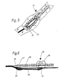
- the closure 34 shown in FIGS. 5 and 6 shows that both the zipper 35 and the seal slide closure 36 have an end piece 37 and 38, respectively.
- the end piece 37 holds the locking elements formed by the teeth together and serves as a movement limitation for the shooting About 39.
- the end piece 38 has wedge-shaped thickenings 40 which engage in the end position of the slide in the corresponding slide channels 41 and seal them.
- the closure shown in Figs. 5 and 6 finds e.g. when using bags and is not divisible.
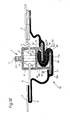
- the closure 42 shown in FIGS. 7 and 8 is intended for articles of clothing and can therefore be divided.
- the end piece 43 which serves to limit the movement of the slider 44, is connected to the right half of the zipper carrier band 45 or the base body 46 of the seal slide fastener in relation to FIG. 7, while the left half of the zipper carrier band 47 in relation to the figure and the base body 48 of the seal slide closure in the direction of arrow 49 can first be inserted into the left slide channel of the slide 44 and then into the left channel of the end piece 43.
- the zipper carrier band 47 can be formed with a reinforced end piece 51.
- the channel 50 may have a side slot which may be open at its top with respect to FIG. 7.
- the right end with respect to FIG. 7 of the base body 46 of the seal slide closure has a thickening 52 for securing so that it cannot be pulled out of the slide closure channel 53 of the slide 44.
- FIG. 9 shows a slide 14 for the closure according to the invention according to FIG. 1 in a perspective manner on an enlarged scale.
- the slide 14 has two input channels 54, 55 and an output channel 56 in its upper part.
- the closure elements are in the input channels 54, 55 of the zipper 2 inserted separately and leave the slider through the channel 56 in the closed state.
- Immediately below the upper section of the slide 14 is the lower section of the slide with the two input channels 57, 58 and the output channel 59. From FIG. 9 it can be seen that the slide is slightly conical from the input side to the output side, which means that threading the closure elements of the zipper or spiral fastener or the seal slide fastener is facilitated.
- the closure elements leave the slide 14 through the channels 56, 59 in the closed state, whereby they lie close together.
- the seal slide closure designated overall by reference number 60, comprises two closure elements 62, 64 which are designed in the manner of a profile and are fastened to the material wall 5 in the manner described above.
- the closure elements 62, 64 bear against one another in a form-locking and non-positive manner in the manner shown in FIG. 10.
- the slide 14 serves to open and close the seal slide fastener, the upper half of which is assigned to the slide fastener and the lower half of which is assigned to the slide slide fastener. If the slide 14 is addressed in the following, this always relates to the lower half of the slide assigned to the seal slide closure.
- the slide 14 comprises a plate 66, on the edge of which is arranged a carrier plate 68, 70 which runs perpendicular to the plate 66.
- a guide plate 72, 74 is arranged on each carrier plate 68, 70 and extends in each case parallel to the plate 66.
- the carrier plate 68 is higher than the carrier plate 70, so that the guide plates 72, 74 are arranged one above the other, the guide plate 74 being approximately in the middle between the plate 66 and the guide plate 72.
- the guide plate 74 projects with its inner section 74a approximately to the middle of the space defined by plate 66, carrier plate 68, guide plate 72 and carrier plate 70, while the section 72a of the guide plate 72 extends to near the plane of the carrier plate 70.
- the closure element 64 is designed such that it engages around the guide plate 74 on all sides. An edge section 76 of the closure element 64 engages over the outwardly projecting plate section 74b of the guide plate 74. A bottom section 78 of the closure element 64 extends along the underside of the guide plate 74 and a further section 80 of the closure element 64 adjoining it engages around the plate section 74a and ends close to it Carrier plate 70. A step running in the longitudinal direction of the closure element 64 is formed in the bottom section 78, the stop surface 82 of which is oriented perpendicular to the direction of movement of the sliding seal closure and points outwards.
- the closure element 62 is generally approximately S-shaped. Its upper curvature section 84 clasps the correspondingly shaped sections 80 and 78 (this section only partially), while the lower curvature section 86 is guided on and engages around the guide plate 72.
- the lower curvature section 86 with its inner surface is over the upper side of the plate section 72a and along the lower side of the guide plate 72 out to its outer end.
- An edge section 88 engages over the plate section 72b of the guide plate 72.
- a step is formed on the lower curvature section 86, which defines a stop surface 90 which lies opposite the stop surface 82.
- the two stop surfaces 82, 90 cause the two closure elements 62, 64 to latch against one another when the sealing slide closure is in the closed state.
- the closure elements 62, 64 assume the configuration shown in FIG. 10.
- the curvature section 84 of the closure element 62 clasps the sections 80, 78 of the closure element 64, this sealing position being locked.
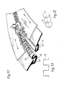
- the curved section 84 is surrounded over its entire length with a wire spring 92, which can be seen particularly clearly from FIGS. 11 to 13.
- This wire spring 92 is curved in the longitudinal direction of the closure in a rectangular or meandering manner, as is indicated in FIG. 13. The wire spring shaped in this way is then bent as required from the flat configuration shown in FIG. 13 and pushed onto the curved section 84.
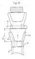
- an end piece 98 is arranged, which serves as a stop for the slide 14.
- the ends of the two halves of the sliding seal closure are suitably welded in a suitable manner and they are in their sealing position relative to one another.
- the edge sections 76 and 88 of the closure elements 62, 64 are removed in an end region 100 of the sliding seal closure.
- the length of the region 100 is at least equal to the distance between the end piece 98 and the start of the V-shaped expansion of the guide channel or the guide plate sections 72b, 74b. The result of this is that in region 100 the expansion forces of the slide normally acting on the slide seal closure cannot come into effect, so that in the end position of the slide shown in FIG. 15 the slide seal closure is continuously sealed until its end.
- closure elements 62, 64 are inevitably held in a sealing position by being guided within the guide channel of the slide 14 by being enclosed by the inner surfaces of the slide guide profile.
Landscapes
- Slide Fasteners (AREA)
- Bag Frames (AREA)
Applications Claiming Priority (2)
| Application Number | Priority Date | Filing Date | Title |
|---|---|---|---|
| DE3700427 | 1987-01-08 | ||
| DE19873700427 DE3700427A1 (de) | 1987-01-08 | 1987-01-08 | Gas- und fluessigkeitsdichter verschluss |
Publications (1)
| Publication Number | Publication Date |
|---|---|
| EP0277320A1 true EP0277320A1 (de) | 1988-08-10 |
Family
ID=6318581
Family Applications (1)
| Application Number | Title | Priority Date | Filing Date |
|---|---|---|---|
| EP87118378A Withdrawn EP0277320A1 (de) | 1987-01-08 | 1987-12-11 | Gas- und flüssigkeitsdichter Verschluss |
Country Status (6)
| Country | Link |
|---|---|
| US (1) | US4875258A (it) |
| EP (1) | EP0277320A1 (it) |
| JP (1) | JPS63174603A (it) |
| DE (1) | DE3700427A1 (it) |
| FI (1) | FI880062L (it) |
| IT (1) | IT1207751B (it) |
Cited By (1)
| Publication number | Priority date | Publication date | Assignee | Title |
|---|---|---|---|---|
| WO1997007702A1 (en) * | 1995-08-23 | 1997-03-06 | Seo Chung Sil | Waterproof double fastener |
Families Citing this family (16)
| Publication number | Priority date | Publication date | Assignee | Title |
|---|---|---|---|---|
| US5924172A (en) * | 1996-06-03 | 1999-07-20 | Cascade Designs, Inc. | Weather resistant structures for conventional slide fasteners and methods for making the same |
| JP3802955B2 (ja) * | 1996-11-27 | 2006-08-02 | 富士機械製造株式会社 | 回路部品装着システム |
| US6361213B2 (en) * | 1999-04-22 | 2002-03-26 | The Procter & Gamble Company | Sliding mechanical closure with consumer-releasable motion-limiting features |
| US20040234171A1 (en) * | 2003-05-19 | 2004-11-25 | Dais Brian C. | Reclosable pouch with closure device that allows venting and/or an air-tight seal |
| US20050076480A1 (en) * | 2003-10-14 | 2005-04-14 | Chen Tan Ming | Zipper slide |
| ITTO20060458A1 (it) * | 2006-06-22 | 2007-12-23 | Ykk Europ Ltd | Cursore per una cerniera lampo |
| JP4689631B2 (ja) | 2007-02-08 | 2011-05-25 | Ykk株式会社 | 液密スライドファスナー並びに液密スライドファスナーの製造方法 |
| FR2951915B1 (fr) * | 2009-10-30 | 2012-01-20 | Delsey Soc | Dispositif de securite pour bagage equipe de fermetures a glissiere |
| JP2012524580A (ja) * | 2009-04-24 | 2012-10-18 | デルセイ | 第1の外側ジッパーと第2の内側ジッパーを含む1つの手荷物用の安全装置 |
| US20100299886A1 (en) * | 2009-05-27 | 2010-12-02 | Eric Fodge | Zipper with removable slider |
| US9706816B2 (en) * | 2014-04-09 | 2017-07-18 | Northeastern University | Zipper guide for facilitating closure of open-ended zipper |
| GB2533796A (en) * | 2014-12-30 | 2016-07-06 | Tan Fu-Hsing | Sealing Strap |
| CN104720212A (zh) * | 2015-04-10 | 2015-06-24 | 新疆际华七五五五职业装有限公司 | 一种防水拉链 |
| US9545134B1 (en) * | 2015-10-14 | 2017-01-17 | Fu-Hsing Tan | Waterproof zipper |
| EP4061178A4 (en) | 2019-11-23 | 2023-12-13 | Talon Technologies Inc. | CURVED ZIPPER |
| US11363860B2 (en) | 2019-11-23 | 2022-06-21 | Talon Technologies, Inc. | Waterproof curved zippers |
Citations (10)
| Publication number | Priority date | Publication date | Assignee | Title |
|---|---|---|---|---|
| US1702426A (en) * | 1928-01-26 | 1929-02-19 | Joseph C Anderegg | Fastener |
| US1959319A (en) * | 1927-07-16 | 1934-05-15 | Hookless Fastener Co | Fastening device |
| US2296468A (en) * | 1942-01-05 | 1942-09-22 | John H Feist | Slide fastener |
| US2306488A (en) * | 1939-09-13 | 1942-12-29 | Morner Hans Georg | Lifesaving and protecting suit |
| FR990158A (fr) * | 1944-03-09 | 1951-09-18 | Dispositif de fermeture souple et étanche, notamment pour vêtements | |
| US2637086A (en) * | 1950-08-31 | 1953-05-05 | Flexigrip Inc | Combined slide fastener |
| US2693013A (en) * | 1951-12-11 | 1954-11-02 | Treg Inc | Sealing closure |
| GB1201290A (en) * | 1969-04-09 | 1970-08-05 | New Zipper Co Ltd | Improvements in or relating to sliding clasp fasteners |
| US4130917A (en) * | 1978-01-16 | 1978-12-26 | The United States Of America As Represented By The Secretary Of The Army | Flexible slide fastener |
| GB2014232A (en) * | 1978-02-08 | 1979-08-22 | Roeder Ind Holdings | Flexible continuous slide closures |
Family Cites Families (15)
| Publication number | Priority date | Publication date | Assignee | Title |
|---|---|---|---|---|
| US2229216A (en) * | 1940-02-09 | 1941-01-21 | Whitehall Patents Corp | Separable fastener |
| US2460853A (en) * | 1945-06-27 | 1949-02-08 | Paul A Siple | Waterproof fastening device |
| GB605599A (en) * | 1945-12-31 | 1948-07-27 | E I Du Pont De Nemurs And Comp | Manufacture of quaternary ammonium compounds in paste form |
| US2641037A (en) * | 1950-04-24 | 1953-06-09 | Treg Inc | Sealing closure |
| US2909822A (en) * | 1954-09-10 | 1959-10-27 | Botti Argentino Benjamin | Continuous linear closing devices |
| US3103051A (en) * | 1960-01-05 | 1963-09-10 | Iwatsuki Frank | Self-energized zipper seal |
| US3509927A (en) * | 1967-10-23 | 1970-05-05 | Minigrip Inc | Bag with carrying handle |
| DE1916228A1 (de) * | 1969-03-29 | 1970-10-08 | Walter Urban | Reissverschluss |
| US3668745A (en) * | 1969-12-18 | 1972-06-13 | Goodrich Co B F | Sealing closure |
| US3624871A (en) * | 1970-05-08 | 1971-12-07 | Frederick N Osterkorn | Covered slide fastener |
| US3948705A (en) * | 1972-07-25 | 1976-04-06 | Steven Ausnit | Method for making multiple plastic bags with reclosable fasteners thereon |
| JPS5832703A (ja) * | 1981-08-20 | 1983-02-25 | ワイケイケイ株式会社 | 気密・水密用スライドファスナ−ストリンガ− |
| US4641400A (en) * | 1983-08-15 | 1987-02-10 | Mpc Containment Systems, Ltd. | Airtight, watertight mechanical seam for joining panels of industrial strength fabrics |
| JPH0216648Y2 (it) * | 1985-07-27 | 1990-05-09 | ||
| US4731911A (en) * | 1986-08-08 | 1988-03-22 | Minigrip, Inc. | Extruded closure strip carrying reactivatable adhesive layer |
-
1987
- 1987-01-08 DE DE19873700427 patent/DE3700427A1/de not_active Withdrawn
- 1987-04-13 IT IT8704814A patent/IT1207751B/it active
- 1987-12-11 EP EP87118378A patent/EP0277320A1/de not_active Withdrawn
-
1988
- 1988-01-07 US US07/141,624 patent/US4875258A/en not_active Expired - Fee Related
- 1988-01-08 FI FI880062A patent/FI880062L/fi not_active Application Discontinuation
- 1988-01-08 JP JP63003028A patent/JPS63174603A/ja active Pending
Patent Citations (10)
| Publication number | Priority date | Publication date | Assignee | Title |
|---|---|---|---|---|
| US1959319A (en) * | 1927-07-16 | 1934-05-15 | Hookless Fastener Co | Fastening device |
| US1702426A (en) * | 1928-01-26 | 1929-02-19 | Joseph C Anderegg | Fastener |
| US2306488A (en) * | 1939-09-13 | 1942-12-29 | Morner Hans Georg | Lifesaving and protecting suit |
| US2296468A (en) * | 1942-01-05 | 1942-09-22 | John H Feist | Slide fastener |
| FR990158A (fr) * | 1944-03-09 | 1951-09-18 | Dispositif de fermeture souple et étanche, notamment pour vêtements | |
| US2637086A (en) * | 1950-08-31 | 1953-05-05 | Flexigrip Inc | Combined slide fastener |
| US2693013A (en) * | 1951-12-11 | 1954-11-02 | Treg Inc | Sealing closure |
| GB1201290A (en) * | 1969-04-09 | 1970-08-05 | New Zipper Co Ltd | Improvements in or relating to sliding clasp fasteners |
| US4130917A (en) * | 1978-01-16 | 1978-12-26 | The United States Of America As Represented By The Secretary Of The Army | Flexible slide fastener |
| GB2014232A (en) * | 1978-02-08 | 1979-08-22 | Roeder Ind Holdings | Flexible continuous slide closures |
Cited By (1)
| Publication number | Priority date | Publication date | Assignee | Title |
|---|---|---|---|---|
| WO1997007702A1 (en) * | 1995-08-23 | 1997-03-06 | Seo Chung Sil | Waterproof double fastener |
Also Published As
| Publication number | Publication date |
|---|---|
| JPS63174603A (ja) | 1988-07-19 |
| FI880062A7 (fi) | 1988-07-09 |
| IT8704814A0 (it) | 1987-04-13 |
| US4875258A (en) | 1989-10-24 |
| FI880062L (fi) | 1988-07-09 |
| FI880062A0 (fi) | 1988-01-08 |
| DE3700427A1 (de) | 1988-07-21 |
| IT1207751B (it) | 1989-06-01 |
Similar Documents
| Publication | Publication Date | Title |
|---|---|---|
| DE68913371T2 (de) | Profilierte Befestigungsvorrichtung. | |
| DE10030185B4 (de) | Fluiddichter Reißverschluß | |
| DE112012004871B4 (de) | Reissverschluss | |
| DE102009053746B4 (de) | Ein wasserfester Gleitverschluss mit kontinuierlichem Gewinde und dessen flüssigkeitsundurchlässiger Aufbau | |
| DE112021004451B4 (de) | Reissverschlusskette und reissverschluss | |
| EP1057424A2 (de) | Verschlussanordnung für Schlitzöffnungen in Wassersportanzügen | |
| DE102005060035B4 (de) | Reißverschluß | |
| DE2748546A1 (de) | Reissverschluss mit wenigstens einem schieber | |
| DE3700427A1 (de) | Gas- und fluessigkeitsdichter verschluss | |
| DE102014211629A1 (de) | Verschiebbares Befestigungselement mit einem Kopplungselement zum Anklemmen mit einem für Flüssigkeiten undurchlässigen Aufbau | |
| DE2231324C3 (de) | Spannverschluß zum Straffen, Entspannen und Halten von zwei Pack-oder Zurrungszwecken dienen den Gurtstücken | |
| DE1785533B1 (de) | Trennbares Endglied fuer Reissverschluesse | |
| DE69417852T2 (de) | Klemmschelle mit sägzahnförmiger Verschlussanordnung | |
| AT389805B (de) | Reissverschluss | |
| DE2907631A1 (de) | Reissverschluss und mit einem solchen versehene kleidungsstuecke, gegenstaende und gutbahnen | |
| DE2856552A1 (de) | Gewebte verschlusskette fuer reissverschluesse | |
| DE69822780T2 (de) | Lineares Profil, welches sich durch mechanisches ineinandergreifen dichtend schliesst | |
| DE3715089A1 (de) | Endanschlag fuer reissverschluesse | |
| DE1186666B (de) | Abgedichteter Reissverschluss | |
| DE2009973C3 (de) | Abgedichteter Reißverschluß | |
| DE2756232A1 (de) | Bandendenverstaerkungen fuer reissverschluesse mit loesbarer endverbindung | |
| DE102024122093B4 (de) | Reißverschluss mit Abdichtungsfunktion | |
| DE102006045246B3 (de) | Reißverschluss, Artikel mit einem Reißverschluss sowie Schieber für einen Reißverschluss | |
| EP0254849A1 (de) | Verschlussband aus Kunststoff | |
| DE3240150A1 (de) | Reversible schnellverbindung |
Legal Events
| Date | Code | Title | Description |
|---|---|---|---|
| PUAI | Public reference made under article 153(3) epc to a published international application that has entered the european phase |
Free format text: ORIGINAL CODE: 0009012 |
|
| AK | Designated contracting states |
Kind code of ref document: A1 Designated state(s): AT BE CH DE ES FR GB IT LI NL SE |
|
| 17P | Request for examination filed |
Effective date: 19881025 |
|
| 17Q | First examination report despatched |
Effective date: 19890823 |
|
| STAA | Information on the status of an ep patent application or granted ep patent |
Free format text: STATUS: THE APPLICATION IS DEEMED TO BE WITHDRAWN |
|
| 18D | Application deemed to be withdrawn |
Effective date: 19900103 |