EP0277382A1 - Aggrégat moteur-compresseur - Google Patents
Aggrégat moteur-compresseur Download PDFInfo
- Publication number
- EP0277382A1 EP0277382A1 EP87202579A EP87202579A EP0277382A1 EP 0277382 A1 EP0277382 A1 EP 0277382A1 EP 87202579 A EP87202579 A EP 87202579A EP 87202579 A EP87202579 A EP 87202579A EP 0277382 A1 EP0277382 A1 EP 0277382A1
- Authority
- EP
- European Patent Office
- Prior art keywords
- motor
- armature
- space
- gas
- pressure
- Prior art date
- Legal status (The legal status is an assumption and is not a legal conclusion. Google has not performed a legal analysis and makes no representation as to the accuracy of the status listed.)
- Granted
Links
- 230000006835 compression Effects 0.000 claims abstract description 19
- 238000007906 compression Methods 0.000 claims abstract description 19
- 230000007423 decrease Effects 0.000 claims description 6
- 230000003534 oscillatory effect Effects 0.000 claims description 4
- 238000001816 cooling Methods 0.000 description 3
- 230000004907 flux Effects 0.000 description 3
- 238000010276 construction Methods 0.000 description 2
- 230000003247 decreasing effect Effects 0.000 description 2
- 230000002349 favourable effect Effects 0.000 description 2
- 230000005540 biological transmission Effects 0.000 description 1
- 230000005494 condensation Effects 0.000 description 1
- 238000009833 condensation Methods 0.000 description 1
- 239000002826 coolant Substances 0.000 description 1
- 230000001419 dependent effect Effects 0.000 description 1
- 238000006073 displacement reaction Methods 0.000 description 1
- 230000005415 magnetization Effects 0.000 description 1
- 238000005057 refrigeration Methods 0.000 description 1
Images
Classifications
-
- F—MECHANICAL ENGINEERING; LIGHTING; HEATING; WEAPONS; BLASTING
- F04—POSITIVE - DISPLACEMENT MACHINES FOR LIQUIDS; PUMPS FOR LIQUIDS OR ELASTIC FLUIDS
- F04B—POSITIVE-DISPLACEMENT MACHINES FOR LIQUIDS; PUMPS
- F04B39/00—Component parts, details, or accessories, of pumps or pumping systems specially adapted for elastic fluids, not otherwise provided for in, or of interest apart from, groups F04B25/00 - F04B37/00
- F04B39/0027—Pulsation and noise damping means
-
- F—MECHANICAL ENGINEERING; LIGHTING; HEATING; WEAPONS; BLASTING
- F01—MACHINES OR ENGINES IN GENERAL; ENGINE PLANTS IN GENERAL; STEAM ENGINES
- F01B—MACHINES OR ENGINES, IN GENERAL OR OF POSITIVE-DISPLACEMENT TYPE, e.g. STEAM ENGINES
- F01B11/00—Reciprocating-piston machines or engines without rotary main shaft, e.g. of free-piston type
- F01B11/02—Equalising or cushioning devices
-
- F—MECHANICAL ENGINEERING; LIGHTING; HEATING; WEAPONS; BLASTING
- F04—POSITIVE - DISPLACEMENT MACHINES FOR LIQUIDS; PUMPS FOR LIQUIDS OR ELASTIC FLUIDS
- F04B—POSITIVE-DISPLACEMENT MACHINES FOR LIQUIDS; PUMPS
- F04B35/00—Piston pumps specially adapted for elastic fluids and characterised by the driving means to their working members, or by combination with, or adaptation to, specific driving engines or motors, not otherwise provided for
- F04B35/04—Piston pumps specially adapted for elastic fluids and characterised by the driving means to their working members, or by combination with, or adaptation to, specific driving engines or motors, not otherwise provided for the means being electric
- F04B35/045—Piston pumps specially adapted for elastic fluids and characterised by the driving means to their working members, or by combination with, or adaptation to, specific driving engines or motors, not otherwise provided for the means being electric using solenoids
Definitions
- the invention relates to a motor-compressor unit comprising a vibration motor having two or more coils around a stator core, parallel to which is arranged a magnet with a stator part above it, one of the poles of said magnet being directed to the core and circularly bent air gaps being present between the stator core and the stator part, while slide elements of an armature traverse in said air gaps a part of an arc of a circle and the armature is rotatable about a motor shaft, which is coupled with a piston body linearly movable in a cylinder, which piston body can vary with one side the volume of a compression space with inlet and outlet valves and can vary with its other side the volume of a gas spring space.
- a motor-compressor unit of the kind described above is known from EP A 0155057.
- the vibrating rotary movement of the armature is converted by means of a transmission into a linear reciprocating movement of the piston-shaped body.
- Such a motor-compressor unit forms a mass spring system, in which the springs are formed by the gas pressures on either side of the piston body and the mass is formed by the mass of the piston body and by the masses of the moving parts of the motor.
- the present invention has for its object to provide a motor-compressor unit of the kind described having an optimum efficiency.
- the invention is based on the recognition of the fact that one of the requirements for an optimum efficiency is that the piston-shaped body performs a reciprocating movement about a central position, which corresponds approximately to the central position of the armature of the motor.
- the motor- compressor unit is characterized in that the gas spring space is solely provided with an inlet valve, which is connected to the same medium supply as the inlet valve of the compression space, while at nominal power and nominal delivery pressure and suction pressure the volume of the gas spring space exceeds the volume of the compression space by such an amount that the spring stiffness of the gas in the gas spring space is equal to the spring stiffness of the gas in the compression space and the piston body performs during operation a vibration about a central position corresponding to the central position of the armature.
- a motor-compressor unit is obtained which in the nominal operating conditions has an optimum efficiency.
- both the delivery pressure and the suction pressure will vary when the motor-compressor unit is used, for example, in a refrigerating system.
- the spring stiffness of the gas in the compression space and in the gas spring space strongly depends upon the delivery pressure and suction pressure so that the natural frequency of the system will also vary with varying delivery pressure and suction pressure. Without any control the maximum efficiency will then consequently be rarely attained.
- a favourable embodiment of the motor-compressor unit according to the invention is characterized in that the suction and/or delivery lead accommodates a controllable restriction, which can be controlled so that with increasing delivery pressure the suction pressure decreases and conversely.
- the invention is based on the recognition of the fact that, when the delivery pressure in the compression space increases, the spring stiffness of the gas in this space increases. When the suction pressure is decreased, the spring stiffness will decrease. When these possibilities are combined, the resulting spring stiffness and hence the natural frequency of the system will remain substantially constant.
- suction pressure Although it is possible to manipulate both the suction pressure and the delivery pressure, it is to be preferred to adapt only the suction pressure to a varied delivery pressure in such a manner that the suction pressure decreases with increasing delivery pressure and increases with decreasing delivery pressure.
- a motor-compressor unit according to the invention in which some variation in natural frequency and central position of the moving system is taken into the bargain, is characterized in that solely the suction lead is provided with a controllable restriction, which keeps the suction pressure constant independently of the delivery pressure.
- a further favourable embodiment of the motor-compressor unit according to the invention is characterized in that the suction-and delivery leads both accommodate a controllable restriction which independently keep the suction pressure and the delivery pressure at a constant low pressure.
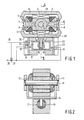
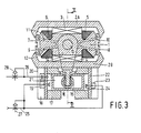
- the motor-compressor comprises a stator core 1 and stator parts 2A and 2B. Between the core 1 and the part 2 is provided a gap in which magnets 3 and 4 are arranged, one of whose poles faces the core. Further, two coils 5 and 7 wound on the stator are present, which can be connected to an alternating voltage.
- stator core 1 In the air gaps between the stator core 1 and the stator part 2 are provided four slide elements 7,8 and 9,10, which can rotate about a motor shaft 13 via armature parts 11 and 12.
- the parts 11 and 12 are connected via a part 14 and a Scottish yoke construction 15 to a piston 16, which is accommodated in a cylinder 17 ao as to be capable of performing a linear reciprocating movement.
- the cylinder 17 is provided on one side with a plate 18, in which an inlet valve 19 and an outlet valve 20 are included, through which gas can flow into and out of a compression space 21.
- a plate 22 including an inlet valve 23 limits a gas spring space 24.
- the inlet valves 19 and 23 adjoin a common suction lead 25, through which working medium can flow to the relevant spaces.
- the outlet valve 20 adjoins a delivery lead 26, to which compressed working medium is supplied by the compressor.
- the leads 25 and 26 may form part, for example, of a cooling circuit in which further a condensor (not shown), a choke valve and an evaporator are arranged.
- a controllable restriction 27 is provided in the suction lead 25.
- each slide part 7,8,9,10 alternately assumes a high and a low value.
- the magnets 3,4 are magnetized so that their direction of magnetization is the same, while further the coils 5 and 6 are interconnected so that the direction of rotation of the current through these coils is also the same so that two slide parts 7,8 and 9,10 arranged diagonally opposite to each other are subjected at the same instant to a high magnetic flux so that they are drawn into the air gap, whereas the remaining two slide parts are subjected to a low flux density and are located outside the gap. This leads to an oscillatory movement of the slide parts and of the armature.
- the piston 16 will then perform a reciprocating movement about a given central position, which is for a large part dependent upon the power supplied to the motor, upon the delivery pressure and suction pressure and upon the spring stiffness of the gas in the compressor space and the gas spring space.
- a feature of the electric motor is that is operates with an optimum efficiency when the armature performs a vibrating osciallatory movement about a central position, the slide parts 7,8 and 9,10 being located by half in their respective air gaps and by half outside these gaps. Since the armature is fixedly coupled with the piston 16, the optimum central position of the piston 16 is thus also fixed and this position is obtained according to the invention in that the cylinder is constructed so that the gas spring space 24 is slightly larger than the compression space, as a result of which it is achieved that the spring stiffness of the gas in the two spaces is substantially the same. Any leakage along the piston etc. is compensated for by providing the gas spring space with solely an inlet valve, so that the suction pressures on both sides of the piston are equal.
- a mass spring system which performs an oscillatory movement about the said central position.
- a motor-compressor has an optimum efficiency when it performs a movement about the central position and is driven by the motor at a frequency approximately corresponding to the resonance frequency of the vibrating mass spring system.
- both the delivery pressure and the suction pressure will vary due to conditions occurring in the system, which is connected to the delivery and suction valves; this may be, for example, a cooling circuit, in which the pressure varies with the ambient temperature.
- the spring stiffness of the gas in the compression space and the gas spring space will also vary so that the resonance frequency of the system may also vary.
- the delivery pressure and suction pressure are adapted, it has nevertheless proved to be possible to keep the effective spring stiffness and hence the resonance frequency equal.
- the suction lead accommodates a controllable restriction 27, which is controlled in dependence upon the pressure in the delivery lead 26 in such a manner that with increasing delivery pressure the restriction is narrowed and the suction pressure decreases.
- the spring stiffnesses and hence the resonance frequency remain unchanged so that in every operating condition the motor-compressor operates with an optimum efficiency, the optimum central position of the piston also remaining unchanged.
- the extent to which the delivery pressure and the suction pressure are controlled with respect to each other depends upon the compressor dimensions. In a compressor with a cylinder bore having a diameter of 25 mm and a piston stroke of 14 mm, the pressures are controlled so that, when the delivery pressure increases by a value P, the suction pressure decreases by a value P.
- both the suction lead 25 and the delivery lead 26 accommodate a controllable restriction 27 and 28 respectively.
- the restriction 27 is controlled in dependence upon the pressure prevailing in the suction lead and keeps this pressure at a constant low value e.g. equal to the minimum pressure which may occur during operation in the evaporates of a cooling circuit connected to the compressor.
- the restriction 28 is controlled in dependence upon the pressure prevailing in the delivery lead 26 and keeps this pressure at a constant low value e.g. equal to the condensation pressure at normal ambient temperature of the cooling medium used in a refrigeration circuit connected to the compressor. Due to the fact that in this embodiment the compressor operates with a constant suction and delivery pressure the resonance frequency will always be the same and thus in every operating condition the compressor unit operates with maximum efficiency.
Landscapes
- Engineering & Computer Science (AREA)
- Mechanical Engineering (AREA)
- General Engineering & Computer Science (AREA)
- Compressor (AREA)
- Compressors, Vaccum Pumps And Other Relevant Systems (AREA)
- Control Of Multiple Motors (AREA)
- Reciprocating, Oscillating Or Vibrating Motors (AREA)
- Structures Of Non-Positive Displacement Pumps (AREA)
Priority Applications (1)
| Application Number | Priority Date | Filing Date | Title |
|---|---|---|---|
| AT87202579T ATE61450T1 (de) | 1986-12-24 | 1987-12-18 | Motor-verdichtereinheit. |
Applications Claiming Priority (2)
| Application Number | Priority Date | Filing Date | Title |
|---|---|---|---|
| NL8603295A NL8603295A (nl) | 1986-12-24 | 1986-12-24 | Motor-compressor eenheid. |
| NL8603295 | 1986-12-24 |
Publications (2)
| Publication Number | Publication Date |
|---|---|
| EP0277382A1 true EP0277382A1 (fr) | 1988-08-10 |
| EP0277382B1 EP0277382B1 (fr) | 1991-03-06 |
Family
ID=19849056
Family Applications (1)
| Application Number | Title | Priority Date | Filing Date |
|---|---|---|---|
| EP87202579A Expired EP0277382B1 (fr) | 1986-12-24 | 1987-12-18 | Aggrégat moteur-compresseur |
Country Status (7)
| Country | Link |
|---|---|
| EP (1) | EP0277382B1 (fr) |
| JP (1) | JPS63167083A (fr) |
| AT (1) | ATE61450T1 (fr) |
| DE (1) | DE3768481D1 (fr) |
| DK (1) | DK673587A (fr) |
| ES (1) | ES2022318B3 (fr) |
| NL (1) | NL8603295A (fr) |
Cited By (3)
| Publication number | Priority date | Publication date | Assignee | Title |
|---|---|---|---|---|
| EP0428212A1 (fr) * | 1989-11-14 | 1991-05-22 | Koninklijke Philips Electronics N.V. | Unité de moteur-compresseur |
| EP0436999A1 (fr) * | 1990-01-11 | 1991-07-17 | Koninklijke Philips Electronics N.V. | Unité de moteur-compresseur |
| WO2007098987A1 (fr) * | 2006-02-28 | 2007-09-07 | BSH Bosch und Siemens Hausgeräte GmbH | Compresseur linéaire à suspension par pression de gaz |
Citations (2)
| Publication number | Priority date | Publication date | Assignee | Title |
|---|---|---|---|---|
| DE408499C (de) * | 1922-11-02 | 1925-01-20 | Ag Deutsche Maschf | Ein- oder mehrstufiger Kolbenkompressor mit Ausgleich des Kraftverbrauchs beim Hin- und Hergang des Kolbens |
| EP0155057A2 (fr) * | 1984-03-13 | 1985-09-18 | Koninklijke Philips Electronics N.V. | Moteur-compresseur |
-
1986
- 1986-12-24 NL NL8603295A patent/NL8603295A/nl not_active Application Discontinuation
-
1987
- 1987-12-18 AT AT87202579T patent/ATE61450T1/de not_active IP Right Cessation
- 1987-12-18 DE DE8787202579T patent/DE3768481D1/de not_active Expired - Lifetime
- 1987-12-18 ES ES87202579T patent/ES2022318B3/es not_active Expired - Lifetime
- 1987-12-18 EP EP87202579A patent/EP0277382B1/fr not_active Expired
- 1987-12-21 DK DK673587A patent/DK673587A/da not_active Application Discontinuation
- 1987-12-23 JP JP62326653A patent/JPS63167083A/ja active Pending
Patent Citations (2)
| Publication number | Priority date | Publication date | Assignee | Title |
|---|---|---|---|---|
| DE408499C (de) * | 1922-11-02 | 1925-01-20 | Ag Deutsche Maschf | Ein- oder mehrstufiger Kolbenkompressor mit Ausgleich des Kraftverbrauchs beim Hin- und Hergang des Kolbens |
| EP0155057A2 (fr) * | 1984-03-13 | 1985-09-18 | Koninklijke Philips Electronics N.V. | Moteur-compresseur |
Cited By (3)
| Publication number | Priority date | Publication date | Assignee | Title |
|---|---|---|---|---|
| EP0428212A1 (fr) * | 1989-11-14 | 1991-05-22 | Koninklijke Philips Electronics N.V. | Unité de moteur-compresseur |
| EP0436999A1 (fr) * | 1990-01-11 | 1991-07-17 | Koninklijke Philips Electronics N.V. | Unité de moteur-compresseur |
| WO2007098987A1 (fr) * | 2006-02-28 | 2007-09-07 | BSH Bosch und Siemens Hausgeräte GmbH | Compresseur linéaire à suspension par pression de gaz |
Also Published As
| Publication number | Publication date |
|---|---|
| DE3768481D1 (de) | 1991-04-11 |
| ATE61450T1 (de) | 1991-03-15 |
| EP0277382B1 (fr) | 1991-03-06 |
| NL8603295A (nl) | 1988-07-18 |
| DK673587D0 (da) | 1987-12-21 |
| ES2022318B3 (es) | 1991-12-01 |
| JPS63167083A (ja) | 1988-07-11 |
| DK673587A (da) | 1988-06-25 |
Similar Documents
| Publication | Publication Date | Title |
|---|---|---|
| US6879064B2 (en) | Linear motor and linear-motor based compressor | |
| US5231337A (en) | Vibratory acoustic compressor | |
| EP2966301B1 (fr) | Compresseur linéaire et moteur linéaire | |
| EP1674725A2 (fr) | Pompe à piston | |
| US20250015648A1 (en) | Rotating electrical machine, manufacturing method therefor, compressor, blower, and refrigeration device equipped with rotating electrical machine | |
| CN114144961A (zh) | 电动机、压缩机以及空调机 | |
| US4721440A (en) | Linear gas compressor | |
| EP0277382B1 (fr) | Aggrégat moteur-compresseur | |
| KR101513611B1 (ko) | 왕복동식 압축기 | |
| JP2004140901A (ja) | リニアモータおよびリニアコンプレッサ | |
| KR20190029024A (ko) | 리니어 압축기 | |
| US4992685A (en) | Reciprocating motor-compressor with W-shaped core | |
| US6700233B2 (en) | Brushless electric motor | |
| EP0155057B1 (fr) | Moteur-compresseur | |
| KR100733043B1 (ko) | 리니어 모터 및 리니어 모터를 구비한 컴프레서 | |
| EP2005564A1 (fr) | Transducteur électromagnétique | |
| US5222877A (en) | Motor-compressor unit | |
| JP2002339863A (ja) | リニアコンプレッサ | |
| US4750870A (en) | Pressure actuated movable head for a resonant reciprocating compressor balance chamber | |
| KR200142465Y1 (ko) | 리니어 모터 | |
| JPS6135149A (ja) | 振動モータ | |
| KR0186143B1 (ko) | 철심가동형 리니어 압축기 구조 | |
| Polman et al. | Free piston electrodynamic gas compressor | |
| JP3249323B2 (ja) | リニアコンプレッサ | |
| CN85107764A (zh) | 电磁斥吸式压缩机 |
Legal Events
| Date | Code | Title | Description |
|---|---|---|---|
| PUAI | Public reference made under article 153(3) epc to a published international application that has entered the european phase |
Free format text: ORIGINAL CODE: 0009012 |
|
| AK | Designated contracting states |
Kind code of ref document: A1 Designated state(s): AT DE ES FR GB IT SE |
|
| 17P | Request for examination filed |
Effective date: 19890208 |
|
| RAP1 | Party data changed (applicant data changed or rights of an application transferred) |
Owner name: WHIRLPOOL INTERNATIONAL B.V. |
|
| 17Q | First examination report despatched |
Effective date: 19900131 |
|
| GRAA | (expected) grant |
Free format text: ORIGINAL CODE: 0009210 |
|
| AK | Designated contracting states |
Kind code of ref document: B1 Designated state(s): AT DE ES FR GB IT SE |
|
| REF | Corresponds to: |
Ref document number: 61450 Country of ref document: AT Date of ref document: 19910315 Kind code of ref document: T |
|
| REF | Corresponds to: |
Ref document number: 3768481 Country of ref document: DE Date of ref document: 19910411 |
|
| ITF | It: translation for a ep patent filed | ||
| ET | Fr: translation filed | ||
| PGFP | Annual fee paid to national office [announced via postgrant information from national office to epo] |
Ref country code: ES Payment date: 19911204 Year of fee payment: 5 |
|
| PGFP | Annual fee paid to national office [announced via postgrant information from national office to epo] |
Ref country code: SE Payment date: 19911220 Year of fee payment: 5 |
|
| PGFP | Annual fee paid to national office [announced via postgrant information from national office to epo] |
Ref country code: AT Payment date: 19911230 Year of fee payment: 5 |
|
| PLBE | No opposition filed within time limit |
Free format text: ORIGINAL CODE: 0009261 |
|
| STAA | Information on the status of an ep patent application or granted ep patent |
Free format text: STATUS: NO OPPOSITION FILED WITHIN TIME LIMIT |
|
| 26N | No opposition filed | ||
| PG25 | Lapsed in a contracting state [announced via postgrant information from national office to epo] |
Ref country code: AT Effective date: 19921218 |
|
| PG25 | Lapsed in a contracting state [announced via postgrant information from national office to epo] |
Ref country code: SE Effective date: 19921219 |
|
| PG25 | Lapsed in a contracting state [announced via postgrant information from national office to epo] |
Ref country code: ES Free format text: LAPSE BECAUSE OF NON-PAYMENT OF DUE FEES Effective date: 19931219 |
|
| EUG | Se: european patent has lapsed |
Ref document number: 87202579.6 Effective date: 19930709 |
|
| REG | Reference to a national code |
Ref country code: FR Ref legal event code: TP Ref country code: FR Ref legal event code: CD Ref country code: FR Ref legal event code: CA |
|
| REG | Reference to a national code |
Ref country code: GB Ref legal event code: 732E |
|
| REG | Reference to a national code |
Ref country code: GB Ref legal event code: IF02 |
|
| PGFP | Annual fee paid to national office [announced via postgrant information from national office to epo] |
Ref country code: GB Payment date: 20031118 Year of fee payment: 17 |
|
| PGFP | Annual fee paid to national office [announced via postgrant information from national office to epo] |
Ref country code: FR Payment date: 20031230 Year of fee payment: 17 |
|
| REG | Reference to a national code |
Ref country code: ES Ref legal event code: FD2A Effective date: 19940113 |
|
| PG25 | Lapsed in a contracting state [announced via postgrant information from national office to epo] |
Ref country code: GB Free format text: LAPSE BECAUSE OF NON-PAYMENT OF DUE FEES Effective date: 20041218 |
|
| GBPC | Gb: european patent ceased through non-payment of renewal fee |
Effective date: 20041218 |
|
| PG25 | Lapsed in a contracting state [announced via postgrant information from national office to epo] |
Ref country code: FR Free format text: LAPSE BECAUSE OF NON-PAYMENT OF DUE FEES Effective date: 20050831 |
|
| REG | Reference to a national code |
Ref country code: FR Ref legal event code: ST |
|
| PGFP | Annual fee paid to national office [announced via postgrant information from national office to epo] |
Ref country code: DE Payment date: 20051117 Year of fee payment: 19 |
|
| PGFP | Annual fee paid to national office [announced via postgrant information from national office to epo] |
Ref country code: IT Payment date: 20061231 Year of fee payment: 20 |
|
| PG25 | Lapsed in a contracting state [announced via postgrant information from national office to epo] |
Ref country code: DE Free format text: LAPSE BECAUSE OF NON-PAYMENT OF DUE FEES Effective date: 20070703 |