EP0277524A2 - Vorrichtung zur Wasseraufbereitung - Google Patents
Vorrichtung zur Wasseraufbereitung Download PDFInfo
- Publication number
- EP0277524A2 EP0277524A2 EP88100543A EP88100543A EP0277524A2 EP 0277524 A2 EP0277524 A2 EP 0277524A2 EP 88100543 A EP88100543 A EP 88100543A EP 88100543 A EP88100543 A EP 88100543A EP 0277524 A2 EP0277524 A2 EP 0277524A2
- Authority
- EP
- European Patent Office
- Prior art keywords
- water
- pipe
- magnets
- sides
- inlet
- Prior art date
- Legal status (The legal status is an assumption and is not a legal conclusion. Google has not performed a legal analysis and makes no representation as to the accuracy of the status listed.)
- Granted
Links
Images

Classifications
-
- C—CHEMISTRY; METALLURGY
- C02—TREATMENT OF WATER, WASTE WATER, SEWAGE, OR SLUDGE
- C02F—TREATMENT OF WATER, WASTE WATER, SEWAGE, OR SLUDGE
- C02F1/00—Treatment of water, waste water, or sewage
- C02F1/48—Treatment of water, waste water, or sewage with magnetic or electric fields
- C02F1/481—Treatment of water, waste water, or sewage with magnetic or electric fields using permanent magnets
-
- C—CHEMISTRY; METALLURGY
- C02—TREATMENT OF WATER, WASTE WATER, SEWAGE, OR SLUDGE
- C02F—TREATMENT OF WATER, WASTE WATER, SEWAGE, OR SLUDGE
- C02F1/00—Treatment of water, waste water, or sewage
- C02F1/28—Treatment of water, waste water, or sewage by sorption
- C02F1/283—Treatment of water, waste water, or sewage by sorption using coal, charred products, or inorganic mixtures containing them
-
- C—CHEMISTRY; METALLURGY
- C02—TREATMENT OF WATER, WASTE WATER, SEWAGE, OR SLUDGE
- C02F—TREATMENT OF WATER, WASTE WATER, SEWAGE, OR SLUDGE
- C02F1/00—Treatment of water, waste water, or sewage
- C02F1/48—Treatment of water, waste water, or sewage with magnetic or electric fields
Definitions
- the invention relates to a device for water treatment, in which the water is guided through magnetic fields.
- DE-GM 84 22 660 describes a device in which two plate-shaped disks form a housing with inlet and outlet openings for the water in the middle of the disks, while the housing forms a circularly symmetrical interior with a central baffle plate, the outer edge of which Distance from the housing is arranged and a coil is housed concentrically to the baffle plate in the housing edge, which generates a field.
- these devices still tend to become blocked and, due to the shape of the window, are difficult to arrange for water pipes because the necessary distance from the wall is not available.
- these devices require an electrical connection and special insulation measures for the current coil.
- the device for water treatment in which the water is passed through magnetic fields, is characterized according to the invention in that two spaced-apart pipe sections are provided with mutually facing longitudinal slots and one pipe section has a water inlet and the second pipe section has a water outlet when connecting the two Longitudinal slots over a plate box, which has permanent magnets arranged on the inside. This creates a flat, space-saving shape that is easy to place on the wall.
- the device for water treatment in which the water is guided through magnetic fields
- the plate box is designed as an exchangeable cassette, consisting of two spaced-apart plates with one another on the inside, but especially one another Opposing magnets, preferably transverse magnet rows, which are arranged at a distance from each other to the water flow and form inlet and outlet slots. This makes it easy to remove the magnetic part for cleaning or for replacement when the device is connected and the water supply is switched off.
- the water passage and thus the efficiency can be further increased in that instead of a two cassettes on both sides in corresponding recesses on the plate box between the two transverse inlet and outlet pipes, each with associated longitudinal slots, can be inserted appropriately and closed by means of cover plates.
- the plate box has an intermediate wall and the transverse tubes are each provided with a longitudinal slot on both sides of the intermediate wall for the associated cassette.
- Sieve internals or filter cartridges and activated carbon cartridges can also prevent constipation and improve water purification and prevent calcification by the magnetic fields.
- the device according to the invention consists of two mutually spaced pipe sections 1 and 2 with mutually associated longitudinal slots 3 and 4, which by a plate box made of plates 5 and 6 with closure sides 7 and 8 are connected.
- the plate 5 with the cross members 7 and 8 is welded to a pipe slot side of 3 and 4, while the second plate 6 is detachably screwed to webs 9, 10 of the other pipe slot side of 3 and 4, whereby easy cleaning is possible.
- permanent magnets 11 and 12 are alternately fastened on the inside of the two plates 5 and 6 at a distance from one another and lying one below the other by means of clamping plate strips 13 and 14. With their magnetic field, these permanent magnets 11 and 12 avoid a connection of the polarization effect Hydrogen carbonates and thus an incrustation (calcification) of pipes, washing machines, dishwashers and the like.
- transverse permanent magnets can be arranged transversely to the water flow on the inner sides of the plates, without any spacing next to and below one another, to form a block, the two blocks lying opposite each other being a distance of 2 to 5 mm have what gives a strong magnetic field effect.
- the plate box between the longitudinal slots of the two pipe sections can also be divided by a central plate, which central plate can be covered on both sides with permanent magnets, such that two water passages are arranged one behind the other.
- a removable half-screen 15 and longitudinal magnetic rods 16 are installed as magnetic filters in the inlet pipe section 1 with water supply line A or A ⁇ in the lower half above the longitudinal slot 3.
- a removable filter cartridge can also be arranged and finally a replaceable activated carbon cartridge can be provided in the outlet pipe section 2 for water improvement, as is not particularly shown here. the water is then drained via B or B ⁇ as shown.
- the half screen 15 or the filter cartridge can be removed and the activated carbon cartridge, as described, can be exchanged; one plate 6 of the plate box can also be unscrewed.
- cleaning can also be carried out via the detachable nozzle A ⁇ to the detachable nozzle B ⁇ by filling in cleaning fluid at A bei and later draining at B ⁇ .
- the device according to the invention consists of two spaced-apart pipe sections 21 and 22, each with a longitudinal slit 23a, b and 24a, b associated with a pipe section, which are formed by a plate box with an intermediate wall 25 and recesses 26, 27 provided on both sides for inserting the cassettes 28, 29 and closure are provided by means of cover plates 30, 31.
- the cassettes 28, 29, which can be inserted into recesses 26, 27 of the plate box on both sides, form the connections for the respective longitudinal slots 23a, b and 24a, b of the tube pieces 21 and 22 with longitudinal gaps 28a and 29a.
- the exchangeable cassettes 28, 29 are at a distance from two screwed plates 32 and 33 are formed, on the inside of which mutually opposite magnet rows 34, 35 are glued transversely to the water flow with the distance forming the longitudinal gaps 28a and 29a.
- the magnets or rows of magnets can be arranged longitudinally to the water flow, as is not particularly shown here and can be arranged alternately in both cases.
- the cassettes 28, 29 can thus be removed from the recesses 26, 27 after the cover plates 30, 31 have been removed and can be taken apart and cleaned by loosening the screws 36, 37, the spacer tubes 38, 39 lying around the screws 36, 37 during assembly again ensure the correct distance.
- the recesses 26, 27 are closed again by external screwing 40 of the plates 30, 31 with the interposition of rank seals 41.
- the water inlet 42 is connected on one pipe 21 and, on the other hand, the water outlet 43 is connected on the other pipe 22.
- inlet and outlet manometers 44a and 44b are arranged on the free pipe sections 21 and 22, respectively.
- magnets 46 are arranged on a pull-through screw 45 with a space between them and an interlayer of antimagnetic disks 47 for division, the magnetic fields of which are exchangeably held.
- the magnets 46 are held on the pull-through screw 45 on the one hand by means of end receptacle 48 in the inlet pipe 21 and on the other hand by means of end cover 49 and screw nut 50.
- a VA sieve tube 51 for particle retention can also be used in the inlet tube 21, which is given if a plastic cage 52 can be connected upstream as a dirt filter at the slots 23a, 23b.
- a VA sieve tube can also be inserted in the outlet tube 22, as is not specifically drawn here, which can optionally be preceded by an activated carbon filter for eliminating foreign taste at the slits.
- Plug 53a, b and 54a, b with sealing sleeves are provided at the inlet and outlet.
- the water thus passes through the inlet 42 with connection 53a into the annular space 55 in the pipe section 21 and from here into the longitudinal slots 23a, 23b and runs on the magnets 34, 35 through longitudinal gaps 28a, 29a and the longitudinal slots 24a, 24b into the pipe section 22 to the outlet 43 with connection 53b on the input side, with the involvement of further magnets 46, possibly a tubular strainer 51 and plastic cage 52, and on the output side, if necessary, a tubular strainer and activated carbon filter.
- the further connection plugs 54a and 54b at the inlet and outlet take the inlet and outlet manometers 44a and 44b, likewise with sealing sleeves.
- the magnets 34, 35 can be arranged transversely and lengthwise as well as standing or lying in the cassettes 28 and 29, respectively, and can be combined into rows.
- Water treatment is understood here above all to mean the conversion of carbonate crystals into square shapes, which no longer bond with one another, causing incrustation and limescale deposits be prevented while the desired calcium remains in the water as a neutral substance. This prevents scale formation. Furthermore, the water can be cleaned, as described, and made odorless.
Landscapes
- Life Sciences & Earth Sciences (AREA)
- Hydrology & Water Resources (AREA)
- Engineering & Computer Science (AREA)
- Environmental & Geological Engineering (AREA)
- Water Supply & Treatment (AREA)
- Chemical & Material Sciences (AREA)
- Organic Chemistry (AREA)
- Water Treatment By Electricity Or Magnetism (AREA)
Abstract
Description
- Die Erfindung betrifft eine Vorrichtung zur Wasseraufbereitung, bei welcher das Wasser durch Magnetfelder geführt wird.
- Solche Vorrichtungen sind bekannt. So ist beispielsweise im DE-GM 84 22 660 ein Gerät beschrieben, bei welchem zwei tellerförmige Scheiben ein Gehäuse bilden mit Ein- und Austrittsöffnungen für das Wasser in der Mitte der Scheiben, während das Gehäuse einen kreissymmetrischen Innenraum bildet mit mittiger Prallplatte, deren Aussenrand im Abstand vom Gehäuse angeordnet ist und konzentrisch zur Prallplatte eine Spule im Gehäuserand untergebracht ist, welche ein Feld erzeugt. Diese Geräte neigen aber nach wie vor zur Verstopfung und sind überdies durch die Scheibenform schlecht bei Wasserleitungen anzuordnen, da der notwendige Abstand zur Wand nicht vorhanden ist. Überdies benötigen diese Geräte für die Stromspule einen elektrischen Anschluß und besondere Isolationsmaßnahmen.
- Es ist nun Aufgabe der Vorrichtung gemäß der Erfindung eine leichter zu reinigende und in der Form platzsparende Anordnung bei effizientem Wasserdurchgang zu schaffen, die gut an der Wand anzuordnen ist und überdies keinen elektrischen Anschluß bedarf.
- Die Vorrichtung zur Wasseraufbereitung, bei welcher das Wasser durch Magnetfelder geführt wird kennzeichnet sich gemäß der Erfindung dadurch, daß zwei im Abstand zueinander verlaufende Rohrstücke mit einander zugekehrten Längsschlitzen versehen sind und das eine Rohrstück einen Wassereinlaß und das zweite Rohrstück einen Wasserauslaß aufweist, bei Verbindung beider Längsschlitze über einen Plattenkasten, welcher innenseitig angeordnete Permanentmagnete aufweist. Hierdurch wird eine flache, raumsparende Form erreicht, die gut an der Wand anzuordnen ist.
- Nach einem weiteren Gedanken der Erfindung kann sich die Vorrichtung zur Wasseraufbereitung, bei welcher das Wasser durch Magnetfelder geführt wird nach der Erfindung dadurch kennzeichnen, daß der Plattenkasten als auswechselbare Kassette ausgebildet ist, bestehend aus zwei im Abstand gehaltenen Platten mit innenseitig wechselweise, insbesondere aber einander gegenüberliegende Magneten, vorzugsweise querlaufenden Magnetreihen, welche zum Wasserdurchlauf im Abstand zueinander angeordnet sind und Ein- und Ausgangsschlitze bilden. Hierdurch wird der leichte Ausbau des Magnetteils zur Reinigung oder zum Austausch bei angeschlossenem Gerät und abgestellter Wasserzufuhr ermöglicht.
- Auch kann der Wasserdurchgang und damit die Effizienz dadurch weiter erhöht werden, daß anstelle von einer zwei Kassetten beidseits in entsprechende Ausnehmungen am Plattenkasten zwischen beiden quer verlaufenden Ein- und Ausgangsrohren mit jeweils zugehörigen Längsschlitzen passend einbringbar und mittels Abdeckplatten verschließbar sind. Hierbei weist bei beidseitig einbringbaren Kassetten der Plattenkasten eine Zwischenwand auf und die quer verlaufenden Rohre sind mit je einem Längsschlitz beidseits der Zwischenwand für die jeweils zugehörige Kassette versehen.
- Durch Siebeinbauten bzw. Filterpatronen und Aktivkohlepatronen kann überdies eine Verstopfung vermieden und Wassererverbesserung erreicht, sowie durch die Magnetfelder einer Verkalkung vorgebeugt werden.
- Zwei bevorzugte Ausführungsformen einer erfindungsgemäßen Vorrichtung sind beispielsweise in der Zeichnung dargestellt und nachfolgend beschrieben und zwar zeigen:
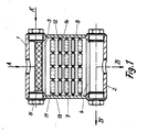
- Fig. 1 einen Längsschnitt durch eine erste Vorrichtung,
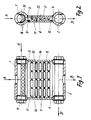
- Fig. 2 einen Querschnitt hierzu und
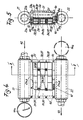
- Fig. 3 einen Einblick in eine zweite Vorrichtung ohne Kassetten teilweise aufgebrochen,
- Fig. 4 einen Einblick in diese Vorrichtung mit eingesetzten und teilweise aufgebrochenen Kassetten und
- Fig. 5 einen Querschnitt hierzu.
- Wie aus Fig. 1 und 2 beim ersten Ausführungsbeispiel ersichtlich wird, besteht die Vorrichtung gemäß der Erfindung aus zwei im Abstand zueinander verlaufenden Rohrstücken 1 und 2 mit einander zugeordneten Längsschlitzen 3 und 4, welche durch einen Plattenkasten aus Platten 5 und 6 mit Verschlußseiten 7 und 8 verbunden sind. Hiervon ist die Platte 5 mit den Querteilen 7 und 8 jeweils an einer Rohrschlitzseite von 3 und 4 angeschweißt, während die zweite Platte 6 an Stegen 9, 10 der anderen Rohrschlitzseite von 3 und 4 lösbar verschraubt ist, wodurch eine leichte Reinigung möglich wird.
- Quer zum Wasserdurchfluß sind an der Innenseite der beiden Platten5 und 6 wechselweise Dauermagneten 11 und 12 im Abstand neben- und untereinander liegend mittels Klemmblechstreifen 13 und 14 befestigt. Diese Dauermagnete 11 und 12 vermeiden mit ihrem Magnetfeld durch Polarisationswirkung eine Verbindung der Hydrogencarbonate und damit eine Verkrustung (Verkalkung) von Rohrleitungen, Waschmaschinen, Geschirrspülautomaten und dergleichen mehr.
- Anstelle der im Abstand zueinander neben- und untereinander liegenden Dauermagnete können quer zum Wasserdurchfluß an den Innenseiten der Platten auch wechselnde Dauermagnete ohne Abstand neben- und untereinanderliegend jeweils zu einem Block zusammengefaßt angeordnet sein, wobei die beiden einander gegenüberliegenden Blocks einen Abstand zueinander von 2 bis 5mm haben, was eine starke Magnetfeldwirkung ergibt.
- Auch kann der Plattenkasten zwischen den Längsschlitzen der beiden Rohrstücke durch eine Mittelplatte geteilt sein, welche Mittelplatte beidseits mit Permanentmagneten belegbar ist, derart, daß zwei Wasserdurchgänge hintereinanderliegend angeordnet sind.
- Wie weiter aus der Zeichnung ersichtlich wird, ist im Eingangsrohrstück 1 bei Wasserzuleitung A bzw. Aʹ in der unteren Hälfte über der Längsschlitzung 3 ein herausnehmbares Halbsieb 15 sowie längslaufende Magnetstäbe 16 als Magnetfilter eingebaut. Anstelle desselben kann auch eine herausnehmbare Filterpatrone angeordnet und schließlich im Ausgangsrohrstück 2 eine auswechselbare Aktivkohle-Patrone zur Wasserverbesserung vorgesehen sein, wie dies hier nicht besonders dargestellt ist. die Wasserableitung erfolgt sodann über B bzw. Bʹ wie eingezeichnet.
- Für eine Reinigung der Vorrichtung kann das Halbsieb 15 bzw. die Filterpatrone herausnehmbar und die Aktivkohle-Patrone, wie geschildert, auswechselbar sein; auch kann die eine Platte 6 des Plattenkastens abschraubbar sein. Schließlich kann bei Absperrventilen am Wassereingang A und -Ausgang B auch eine Reinigung über den lösbaren Stutzen Aʹ zum lösbaren Stutzen Bʹ durch Einfüllen von Reinigungsflüssigkeit bei Aʹ und späterem Ablassen bei Bʹ erfolgen.
- Wie weiter aus Fig. 3 bis 5 beim zweiten Ausführungsbeispiel ersichtlich wird, besteht die Vorrichtung gemäß der Erfindung aus zwei im Abstand zueinander verlaufenden Rohrstücken 21 und 22 mit jeweils einem Rohrstück zugeordneten Längsschlitzen 23a, b und 24a, b welche durch einen Plattenkasten mit Zwischenwand 25 und beidseits vorgesehenen Ausnehmungen 26, 27 zum Einsetzen der Kassetten 28, 29 sowie Verschluß mittels Abdeckplatten 30,31 versehen sind.
- Die beidseits in Ausnehmungen 26,27 des Plattenkastens einbringbare Kassetten 28, 29 bilden mit Längsspalten 28a und 29a die Anschlüsse für die jeweiligen Längsschlitze 23a, b und 24a, b der Rohrstücke 21 und 22. Die auswechselbaren Kassetten 28, 29 sind aus zwei im Abstand verschraubten Platten 32 und 33 gebildet, an deren Innenseite quer zum Wasserdurchlauf einander gegenüberliegende Magnetreihen 34, 35 mit die Längsspalten 28a und 29a bildendem Abstand eingeklebt sind. Auch können die Magnete bzw. Magnetreihen längs zum Wasserdurchlauf angeordnet sein, wie dies hier nicht besonders dargestellt ist und in beiden Fällen wechselweise angeordnet sein. Die Kassetten 28, 29 lassen sich somit aus den Ausnehmungen 26, 27 nach Abnahme der Abdeckplatten 30,31 herausnehmen und durch Lösen der Schrauben 36,37 auseinander nehmen und reinigen, wobei beim Zusammenbau die um die Schrauben 36, 37 liegenden Distanzrohre 38, 39 wiederum für den richtigen Abstand sorgen. Nach dem Einsetzen erfolgt der Verschluß der Ausnehmungen 26,27 wiederum durch Außenverschraubung 40 der Platten 30, 31 unter Zwischenlage von Rangdichtungen 41.
- An den Rohrstücken 21 und 22 wird am einen Rohr 21 einerseits der Wassereinlaß 42 und am anderen Rohr 22 andererseits der Wasserauslaß 43 angeschlossen. Wechselweise hierzu sind an den freien Rohrstücken 21 bzw. 22 Ein- und Ausgangsmanometer 44a und 44b angeordnet.
- Im Eingangsrohr 21 sind auf einer Durchzugsschraube 45 Magnete 46 unter Zwischenraum zu demselben und Zwischen -lage antimagnetischer Scheiben 47 zur Aufteilung deren Magnetfelder auswechselbar aufgereiht gehalten. Hierbei sind die Magnete 46 auf der Durchzugsschraube 45 einerseits mittels Endaufnahme 48 im Eingangsrohr 21 und andererseits mittels Abschlußdeckel 49 und Schraubmutter 50 gehalten.
- Im Eingangsrohr 21 kann ferner ein VA-Siebrohr 51 zur Teilchen-Rückhaltung eingesetzt sein, welchem gegeben falls ein Kunststoffkäfig 52 als Schmutzfilter an den Schlitzungen 23a, 23b vorgeschaltet sein kann. In entsprechender Weise kann auch, wie hier nicht besonders gezeichnet, im Ausgangsrohr 22 ein VA-Siebrohr eingesetzt sein, welchem gegebenenfalls ein Aktivkohlefilter zur Beseitigung von Fremdgeschmack an den Schlitzungen vorgeschaltet sein kann. Am Ein- und Ausgang sind Anschlußstopfen 53a,b und 54a, b mit Dichtungsmanschetten vorgesehen.
- Das Wasser tritt somit über den Einlaß 42 mit Anschluß 53a in den Ringraum 55 im Rohrstück 21 und von hier in die Längsschlitze 23a, 23b und läuft an den Magneten 34, 35 durch Längsspalte 28a, 29a und die Längsschlitze 24a, 24b in das Rohrstück 22 zum Auslaß 43 mit Anschluß 53b jeweils eingangsseitig noch unter Einschaltung von weiteren Magneten 46 gegebenenfalls einem Rohrsieb 51 und Kunststoffkäfig 52 sowie ausgangsseitig gegebenenfalls einem Rohrsieb und Aktivkohlefilter. Die weiteren Anschlußstopfen 54a und 54b am Ein- bzw. Ausgang nehmen die Ein- und Ausgangsmanometer 44a und 44b auf ebenfalls mit Dichtungsmanschetten.
- Die Magnete 34, 35 können quer und längs sowie stehend oder liegend in den Kassetten 28 bzw. 29 angeordnet und jeweils zu Reihen zusammengeschlossen sein.
- Unter Wasseraufbereitung wird hier vor allem verstanden die Umwandlung von Karbonatkristallen in quadratische Formen, welche sich nicht mehr miteinander verbinden, wodurch eine Verkrustung und Kalkablagerungen ver hindert werden, während das erwünschte Kalzium als neutrale Substanz im Wasser verbleibt. Somit wird die Kesselsteinbildung verhindert. Desweiteren kann das Wasser, wie vorgeschildert, feingereinigt und geruchsfrei gemacht werden.
Claims (16)
dadurch gekennzeichnet, daß bei dem Plattenkasten die eine Platte mit zwei Querseiten jeweils entlang der einen Rohrschlitzseite angebracht ist, währende die zweite Platte an Stegen der anderen Rohrschlitzseite lösbar verschraubt ist.
dadurch gekennzeichnet, daß quer zum Wasserdurchfluß an den Innenseiten der beiden Platten wechselweise Dauermagnete in Reihe im Abstand neben- und untereinanderliegend mittels Klemmblechstreifen befestigt sind.
dadurch gekennzeichnet, daß quer zum Wasserdurchfluß an den Innenseiten der Platten wechselnde Dauermagnete ohne Abstand neben- und untereinanderliegend jeweils zu einem Block zusammengefaßt angeordnet sind, wobei die beiden einander gegenüberliegenden Blocks insbes. einen Abstand zueinander von 2 bis 5mm haben.
dadurch gekennzeichnet, daß der Plattenkasten zwischen den Längsschlitzen der beiden Rohrstücke durch eine Mittelplatte geteilt ist, welche Mittelplatte beidseits mit Permanentmagneten belegbar ist, derart, daß zwei Wasserdurchgänge neben bzw. hintereinanderliegend angeordnet sind.
dadurch gekennzeichnet,daß ein oder zwei Kasetten einer bzw. beidseits in entsprechende Ausnehmungen am Plattenkasten zwischen beiden quer verlaufenden Ein- und Ausgangsrohren mit jeweils zugehörigen Längsschlitzen passend einbringbar und mittels Abdeckplatten verschließbar sind.
dadurch gekennzeichnet, daß bei beidseitig einbringbaren Kassetten der Plattenkasten eine Zwischenwand aufweist und die quer verlaufenden Rohre mit je einem Längsschlitz beidseits der Zwischenwand für die jeweils zugehörige Kassette versehen sind.
dadurch gekennzeichnet, daß bei quer bzw. längs zum Wasserdurchlauf einander gegenüberliegend oder zueinander wechselweise angeordneten Magneten dieselben an den Innenwänden der Kassetten vorzugsweise eingeklebt sind.
dadurch gekennzeichnet, daß die beiden Platten jeder Kassette mittels Schrauben unter Zwischenschaltung von Distanzrohren lösbar miteinander verbunden sind.
dadurch gekennzeichnet, daß die ein- oder beidseitigen Abdeckplatten des Plattenkastens zwischen den beiden quer verlaufenden Rohren mittels Schrauben wasser-und druckdicht unter Zwischenlage einer Dichtung aufgebracht sind.
dadurch gekennzeichnet, daß auch im Eingangsrohr Magnete mit außenseitigem Zwischenraum angeordnet und vorzugsweise mittels einer Durchzugsschraube auswechselbar gehalten sind, wobei zwischen den aufgereihten Magneten antimagnetische Scheiben zur Trennung der Magnetfelder eingesetzt sein können.
dadurch gekennzeichnet, daß die Magnete auf der Durchzugsschraube einerseits mittels Verschlußstopfen im Eingangsrohr und andererseits mittels Abschlußdeckel und Schraubmutter aufgereiht gehalten sind.
dadurch gekennzeichnet, daß im Eingangsrohr ein Siebrohr eingesetzt ist, welchem gegebenenfalls noch ein Kunststoffkäfig als Schmutzfilter an den Schlitzungen nachgeschaltet ist.
dadurch gekennzeichnet, daß im Ausgangsrohr ein Siebrohr eingesetzt ist, welchem gegebenenfalls noch ein Aktivkohlefilter an den Schlitzungen vorgeschaltet ist.
dadurch gekennzeichnet, daß am Ein- und Ausgangsrohr die Wasserein- bzw. Auslässe wechselweise angeschlossen sind, während am jeweils freien Rohrstutzen Ein- und Ausgangsmanometer angeordnet sind.
Priority Applications (1)
| Application Number | Priority Date | Filing Date | Title |
|---|---|---|---|
| AT88100543T ATE54435T1 (de) | 1987-02-04 | 1988-01-16 | Vorrichtung zur wasseraufbereitung. |
Applications Claiming Priority (4)
| Application Number | Priority Date | Filing Date | Title |
|---|---|---|---|
| DE8701627U DE8701627U1 (de) | 1987-02-04 | 1987-02-04 | Vorrichtung zur Wasserentkalkung |
| DE8701627U | 1987-02-04 | ||
| DE8716322U DE8716322U1 (de) | 1987-12-10 | 1987-12-10 | Vorrichtung zur Wasseraufbereitung |
| DE8716322U | 1987-12-10 |
Publications (3)
| Publication Number | Publication Date |
|---|---|
| EP0277524A2 true EP0277524A2 (de) | 1988-08-10 |
| EP0277524A3 EP0277524A3 (en) | 1988-10-05 |
| EP0277524B1 EP0277524B1 (de) | 1990-07-11 |
Family
ID=25951501
Family Applications (1)
| Application Number | Title | Priority Date | Filing Date |
|---|---|---|---|
| EP88100543A Expired - Lifetime EP0277524B1 (de) | 1987-02-04 | 1988-01-16 | Vorrichtung zur Wasseraufbereitung |
Country Status (3)
| Country | Link |
|---|---|
| EP (1) | EP0277524B1 (de) |
| DE (1) | DE3860296D1 (de) |
| ES (1) | ES2016117B3 (de) |
Cited By (3)
| Publication number | Priority date | Publication date | Assignee | Title |
|---|---|---|---|---|
| EP0352213A1 (de) * | 1988-07-22 | 1990-01-24 | Liquitech Holding S.A. | Element für Flüssigkeitsaufbereitung |
| FR2676434A1 (fr) * | 1991-05-16 | 1992-11-20 | Rer Sarl | Dispositif anti-tartre mono-bloc de filtration et de traitement des eaux, a faisceaux tubulaires filtrant et magnetiques. |
| FR2684898A1 (fr) * | 1991-12-13 | 1993-06-18 | Ladriere Serge | Appareil pour soumettre un produit coulant, notamment un fluide, particulierement un liquide, a l'action d'un champ magnetique. |
Family Cites Families (2)
| Publication number | Priority date | Publication date | Assignee | Title |
|---|---|---|---|---|
| CH497204A (de) * | 1967-02-01 | 1970-10-15 | Kunstseidenwerk Clara Zetkin V | Einrichtung zur Aussonderung magnetischer Fremdkörper aus einer hochviskosen Flüssigkeit |
| US4366053A (en) * | 1981-05-15 | 1982-12-28 | Descal-A-Matic Corporation | Magnetic liquid treating device |
-
1988
- 1988-01-16 EP EP88100543A patent/EP0277524B1/de not_active Expired - Lifetime
- 1988-01-16 DE DE8888100543T patent/DE3860296D1/de not_active Expired - Lifetime
- 1988-01-16 ES ES88100543T patent/ES2016117B3/es not_active Expired - Lifetime
Cited By (4)
| Publication number | Priority date | Publication date | Assignee | Title |
|---|---|---|---|---|
| EP0352213A1 (de) * | 1988-07-22 | 1990-01-24 | Liquitech Holding S.A. | Element für Flüssigkeitsaufbereitung |
| FR2676434A1 (fr) * | 1991-05-16 | 1992-11-20 | Rer Sarl | Dispositif anti-tartre mono-bloc de filtration et de traitement des eaux, a faisceaux tubulaires filtrant et magnetiques. |
| FR2684898A1 (fr) * | 1991-12-13 | 1993-06-18 | Ladriere Serge | Appareil pour soumettre un produit coulant, notamment un fluide, particulierement un liquide, a l'action d'un champ magnetique. |
| WO1993012040A1 (fr) * | 1991-12-13 | 1993-06-24 | Serge Ladriere | Appareil pour soumettre un produit coulant, notamment un fluide, particulierement un liquide, a l'action d'un champ magnetique |
Also Published As
| Publication number | Publication date |
|---|---|
| EP0277524B1 (de) | 1990-07-11 |
| EP0277524A3 (en) | 1988-10-05 |
| ES2016117B3 (es) | 1990-10-16 |
| DE3860296D1 (de) | 1990-08-16 |
Similar Documents
| Publication | Publication Date | Title |
|---|---|---|
| WO1992011923A1 (de) | Vorrichtung zum reinigen der bearbeitungsflüssigkeit für eine elektroerosive oder elektrochemische bearbeitungsmaschine | |
| DE2803224C2 (de) | Selbstreinigende Filtervorrichtung | |
| DE2241450B2 (de) | Vorrichtung und Verfahren zum Reinigen einer Kammer mit einer semipermeablen Membran | |
| EP1284239A2 (de) | Gerät zur elektrophysikalischen Wasserbehandlung | |
| DE69521769T2 (de) | Vorrichtung zum Herstellen von magnetisiertem Wasser und Magnetfeldgenerator | |
| DE69415910T2 (de) | Spiralförmig gewickelter Filtrationsmodul mit einem Flansch zur Verhinderung der Bypass-Strömung | |
| EP2159197A1 (de) | Verfahren und Vorrichtung zur Behandlung von Wasser | |
| EP0277524B1 (de) | Vorrichtung zur Wasseraufbereitung | |
| DE202007001107U1 (de) | Wasserverteiler für den parallelen Anschluss mehrerer Wasserbehandlungsgeräte | |
| DE7622505U1 (de) | Vorrichtung zur diffusion von substanzen zwischen zwei fliessmitteln | |
| EP0807605B1 (de) | Gerät zum Entsalzen und Aufbereiten von Wasser | |
| DE2318755C2 (de) | Doppelstrom-Elektromagnetfilter | |
| WO2002074411A1 (de) | Bierfilter | |
| DE102018213355A1 (de) | Wasseranschluss-Bauteil für wenigstens eine regenerierbare Wasserbehandlungseinheit | |
| DE742832C (de) | Vorrichtung zum Abscheiden von spezifisch schweren Verunreinigungen aus Fluessigkeiten | |
| DE60218065T2 (de) | Filtrationsvorrichtung | |
| DE8716322U1 (de) | Vorrichtung zur Wasseraufbereitung | |
| DE102007002016B4 (de) | Gerät zur Wasserbehandlung | |
| DE102017000648A1 (de) | Spülverteilervorrichtung und Spülverfahren | |
| WO2017109047A1 (de) | Deionisierungsgerät | |
| DE102021002121A1 (de) | Ionentauscher | |
| DE8701627U1 (de) | Vorrichtung zur Wasserentkalkung | |
| DE3341281A1 (de) | Fluessigkeitsfilter | |
| DE2660630C2 (de) | Hohlfaserdialysator | |
| DE2916634A1 (de) | Verfahren und einrichtung zum abscheiden von sinter o.dgl. magnetisch artverwandten teilchen aus brauch- oder abwasser |
Legal Events
| Date | Code | Title | Description |
|---|---|---|---|
| PUAI | Public reference made under article 153(3) epc to a published international application that has entered the european phase |
Free format text: ORIGINAL CODE: 0009012 |
|
| AK | Designated contracting states |
Kind code of ref document: A2 Designated state(s): AT BE CH DE ES FR GB IT LI LU NL SE |
|
| PUAL | Search report despatched |
Free format text: ORIGINAL CODE: 0009013 |
|
| AK | Designated contracting states |
Kind code of ref document: A3 Designated state(s): AT BE CH DE ES FR GB IT LI LU NL SE |
|
| 17P | Request for examination filed |
Effective date: 19890223 |
|
| 17Q | First examination report despatched |
Effective date: 19891123 |
|
| GRAA | (expected) grant |
Free format text: ORIGINAL CODE: 0009210 |
|
| AK | Designated contracting states |
Kind code of ref document: B1 Designated state(s): AT BE CH DE ES FR GB IT LI LU NL SE |
|
| REF | Corresponds to: |
Ref document number: 54435 Country of ref document: AT Date of ref document: 19900715 Kind code of ref document: T |
|
| ET | Fr: translation filed | ||
| GBT | Gb: translation of ep patent filed (gb section 77(6)(a)/1977) | ||
| REF | Corresponds to: |
Ref document number: 3860296 Country of ref document: DE Date of ref document: 19900816 |
|
| ITF | It: translation for a ep patent filed | ||
| PLBE | No opposition filed within time limit |
Free format text: ORIGINAL CODE: 0009261 |
|
| STAA | Information on the status of an ep patent application or granted ep patent |
Free format text: STATUS: NO OPPOSITION FILED WITHIN TIME LIMIT |
|
| 26N | No opposition filed | ||
| PGFP | Annual fee paid to national office [announced via postgrant information from national office to epo] |
Ref country code: FR Payment date: 19911213 Year of fee payment: 5 |
|
| PGFP | Annual fee paid to national office [announced via postgrant information from national office to epo] |
Ref country code: LU Payment date: 19911218 Year of fee payment: 5 Ref country code: BE Payment date: 19911218 Year of fee payment: 5 |
|
| PGFP | Annual fee paid to national office [announced via postgrant information from national office to epo] |
Ref country code: AT Payment date: 19911219 Year of fee payment: 5 |
|
| PGFP | Annual fee paid to national office [announced via postgrant information from national office to epo] |
Ref country code: CH Payment date: 19911220 Year of fee payment: 5 |
|
| PGFP | Annual fee paid to national office [announced via postgrant information from national office to epo] |
Ref country code: ES Payment date: 19920116 Year of fee payment: 5 |
|
| PGFP | Annual fee paid to national office [announced via postgrant information from national office to epo] |
Ref country code: SE Payment date: 19920117 Year of fee payment: 5 |
|
| ITTA | It: last paid annual fee | ||
| PGFP | Annual fee paid to national office [announced via postgrant information from national office to epo] |
Ref country code: NL Payment date: 19920131 Year of fee payment: 5 |
|
| EPTA | Lu: last paid annual fee | ||
| PGFP | Annual fee paid to national office [announced via postgrant information from national office to epo] |
Ref country code: GB Payment date: 19920413 Year of fee payment: 5 |
|
| PG25 | Lapsed in a contracting state [announced via postgrant information from national office to epo] |
Ref country code: LU Free format text: LAPSE BECAUSE OF NON-PAYMENT OF DUE FEES Effective date: 19930116 Ref country code: GB Effective date: 19930116 Ref country code: AT Effective date: 19930116 |
|
| PG25 | Lapsed in a contracting state [announced via postgrant information from national office to epo] |
Ref country code: SE Effective date: 19930117 |
|
| PG25 | Lapsed in a contracting state [announced via postgrant information from national office to epo] |
Ref country code: ES Free format text: LAPSE BECAUSE OF NON-PAYMENT OF DUE FEES Effective date: 19930118 |
|
| PG25 | Lapsed in a contracting state [announced via postgrant information from national office to epo] |
Ref country code: LI Effective date: 19930131 Ref country code: CH Effective date: 19930131 Ref country code: BE Effective date: 19930131 |
|
| BERE | Be: lapsed |
Owner name: SAUER ROLF GEORG Effective date: 19930131 |
|
| PG25 | Lapsed in a contracting state [announced via postgrant information from national office to epo] |
Ref country code: NL Effective date: 19930801 |
|
| GBPC | Gb: european patent ceased through non-payment of renewal fee |
Effective date: 19930116 |
|
| NLV4 | Nl: lapsed or anulled due to non-payment of the annual fee | ||
| PG25 | Lapsed in a contracting state [announced via postgrant information from national office to epo] |
Ref country code: FR Effective date: 19930930 |
|
| REG | Reference to a national code |
Ref country code: CH Ref legal event code: PL |
|
| REG | Reference to a national code |
Ref country code: FR Ref legal event code: ST |
|
| PGFP | Annual fee paid to national office [announced via postgrant information from national office to epo] |
Ref country code: DE Payment date: 19940819 Year of fee payment: 7 |
|
| EUG | Se: european patent has lapsed |
Ref document number: 88100543.3 Effective date: 19930810 |
|
| PG25 | Lapsed in a contracting state [announced via postgrant information from national office to epo] |
Ref country code: DE Effective date: 19951003 |
|
| REG | Reference to a national code |
Ref country code: ES Ref legal event code: FD2A Effective date: 19990405 |
|
| PG25 | Lapsed in a contracting state [announced via postgrant information from national office to epo] |
Ref country code: IT Free format text: LAPSE BECAUSE OF NON-PAYMENT OF DUE FEES;WARNING: LAPSES OF ITALIAN PATENTS WITH EFFECTIVE DATE BEFORE 2007 MAY HAVE OCCURRED AT ANY TIME BEFORE 2007. THE CORRECT EFFECTIVE DATE MAY BE DIFFERENT FROM THE ONE RECORDED. Effective date: 20050116 |