EP0277582A2 - Einheit für Kompressoren bestehend aus thermostatischem Ventil und Ölfilter - Google Patents
Einheit für Kompressoren bestehend aus thermostatischem Ventil und Ölfilter Download PDFInfo
- Publication number
- EP0277582A2 EP0277582A2 EP88101074A EP88101074A EP0277582A2 EP 0277582 A2 EP0277582 A2 EP 0277582A2 EP 88101074 A EP88101074 A EP 88101074A EP 88101074 A EP88101074 A EP 88101074A EP 0277582 A2 EP0277582 A2 EP 0277582A2
- Authority
- EP
- European Patent Office
- Prior art keywords
- oil
- thermostatic
- valve
- fact
- casing
- Prior art date
- Legal status (The legal status is an assumption and is not a legal conclusion. Google has not performed a legal analysis and makes no representation as to the accuracy of the status listed.)
- Granted
Links
Images
Classifications
-
- F—MECHANICAL ENGINEERING; LIGHTING; HEATING; WEAPONS; BLASTING
- F04—POSITIVE - DISPLACEMENT MACHINES FOR LIQUIDS; PUMPS FOR LIQUIDS OR ELASTIC FLUIDS
- F04C—ROTARY-PISTON, OR OSCILLATING-PISTON, POSITIVE-DISPLACEMENT MACHINES FOR LIQUIDS; ROTARY-PISTON, OR OSCILLATING-PISTON, POSITIVE-DISPLACEMENT PUMPS
- F04C29/00—Component parts, details or accessories of pumps or pumping installations, not provided for in groups F04C18/00 - F04C28/00
- F04C29/04—Heating; Cooling; Heat insulation
-
- F—MECHANICAL ENGINEERING; LIGHTING; HEATING; WEAPONS; BLASTING
- F04—POSITIVE - DISPLACEMENT MACHINES FOR LIQUIDS; PUMPS FOR LIQUIDS OR ELASTIC FLUIDS
- F04C—ROTARY-PISTON, OR OSCILLATING-PISTON, POSITIVE-DISPLACEMENT MACHINES FOR LIQUIDS; ROTARY-PISTON, OR OSCILLATING-PISTON, POSITIVE-DISPLACEMENT PUMPS
- F04C29/00—Component parts, details or accessories of pumps or pumping installations, not provided for in groups F04C18/00 - F04C28/00
- F04C29/02—Lubrication; Lubricant separation
- F04C29/026—Lubricant separation
Definitions
- This invention refers to a device for the circulation of the oil for lubrication and for cooling the air in compressors of the rotary type and, in particular, is directed to a special arrangement of a thermostatic valve and recycling filter for the lubrication and cooling oil to considerably simplify the construction of the compressor and improve lubrication in operating conditions of particularly low temperatures; besides this, it allows easy inspection and/or substitution of both the filter and the thermostatic valve.
- the thermostatic valve comprises a hollow cylindrical body sealingly housed inside the above-mentioned casing, and a closing cylindrical member operated by a thermostatic control element; the cylindrical member slides between two extreme operative positions in which it opens or closes some exit ports for the oil towards a passage for the direct recycling of the oil from the compressor oil chamber to the stator chamber, and respectively for connecting a cooling circuit towards the above mentioned recycling filter.
- the oil filter and the thermostatic valve are made accessible by removing a closure cover of said cylindrical casing so as to be easily removable for maintenance or substitution.
- a rotary air compressor of the type with radial blades comprises an external cylindrical body defining an annular chamber 11, only partially shown, in which a suitable quantity of oil necessary for the operation of the compressor is contained, and an internal cylindrical body 12, also referred to as stator, which defines a chamber 13 in which, as per se known, a blade rotor rotates (not shown).
- stator also referred to as stator
- stator which defines a chamber 13 in which, as per se known, a blade rotor rotates (not shown).
- the whole compressor, with all its relative automatic control devices, is not shown completely here, with the exception of the oil circulation device, since it does not constitute an innovative part of the present invention and is realizable in any of several ways.
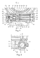
- a cylindrical casing 14 In a position underneath the body 10 of the compressor and placed in direct contact with the lower part of the oil chamber 11 is a cylindrical casing 14 in which a thermostatic valve 15 and a filter 16 are housed or coaxially arranged in alignment with each other.
- the thermostatic valve 15 comprises a hollow cylindrical body 17 in the form of a cup-shaped element, the closed bottom 17a of which is facing towards the filter 16.
- the inside of the hollow body 17 is in communication with the oil chamber 11 of the compressor by means of a lateral inlet hole 18 aligned with a hole 19 which opens towards the bottom of the oil chamber 11.
- a first set of exit ports 20 which ports communicate, through longitudinal passages or channels 21 with the space 22 in which the filtering cartridge 23 is housed, said space 22 for the filter being a continuation of the space in which the valve 15 is housed.
- the inside 24 of the filter cartridge in its turn communicates on one side with a conduit 25 which rectckes the oil directly or through suitable distributors (not shown) inside the chamber 13 of the stator.
- valve body 17 terminates in correspondence with a second exit port 26 in the casing 14 which is connected to an inlet port 27 of the filter space 22 by means of a branched off circuit for cooling the oil, comprising a heat exchanger 28.
- an axially hollow cylinder or closing member 29 which sealingly slides between a first end position, shown in Fig. 1, against an annular edge 30 of a closure cover 31, in which position the closing member completely closes the oil passage towards the second exit port 26, and a second operative position opposite the preceding one, in which the closing member 29 closes the radial ports 20 of direct communication with the filter 16 against an annular seat 32 on the bottom of the cup-shaped element mentioned above.
- the cylindrical closing member 29 is moved between its two end positions by means of a thermostatic control element 33 for example of the wax type, or equivalent element, which, through changes of the temperature of the oil coming from the chamber 11 is extended or retracted thus moving the closing member mentioned above.
- a thermostatic control element 33 for example of the wax type, or equivalent element, which, through changes of the temperature of the oil coming from the chamber 11 is extended or retracted thus moving the closing member mentioned above.
- the bulb of the thermostatic element 33 is fastened to a supporting member inside the cylinder 29 surrounded by a set of holes 34 for the passage of the oil, while the rod 35 of the thermostatic element is fastened to the cover 31 in any suitable way; for example, by means of a cup member 36 housed in a seat in the cover 31 and pushed towards the above-mentioned shaft by a spring 37.
- a second spring 38 is disposed between the bottom 17a of the valve body 17 and the perforated support member 17b for the thermostatic element 33 in the closing cylinder 29 to push the cylinder towards the above mentioned first operative position, thus opposing the action of the thermostatic element 33.
- the cartridge 23 of the filter can be withdrowen and removed simply by removing the end closure cover 39 of the housing 14 since the cartridge 23 of the filter is fixed to the cover 39 by means of a tie rod 40 as shown.
- the cylinder 29 of the thermostatic valve 15, operated by the element 33 sensitive to temperature moves gradually from one position, where the passage 26 towards the conduit leading to the heat exchanger 28 is completely closed and the direct passages 20 and 21 to the oil filter 16 are completely open, to the opposite position, where the condition of the above-mentioned passages is reversed.
- the thermostatic bulb 33 with which it comes in contact pushes out the rod 35 and forces the closing cylinder 29 to move towards the right, partially closing the passage ports 20 leading to the oil filter and uncovering contemporaneously part of the port 42 towards the opening 26 connected to the conduit towards the cooler 28. Therefore, part of the oil will begin to flow through the appropriate holes 34 in the closing cylinder, and from these towards the exit 26 connected to the cooler 28.
- the cylinder 29 When the maximum calibration temperature is reached, the cylinder 29 will have completely closed the direct passage towards the filter 16 and all the oil will have to circulate through the cooler 28 to return to the filter 16 by an appropriate return conduit connected to the inlet port 27 of the filter housing.
- a device is supplied for the circulation and cooling of the oil passing from the oil chamber of a rotary compressor to the stator chamber, which makes use of a particular arrangement of a unit comprising a thermostatic valve and an oil circulation filter, housed and aligned in a single casing positioned underneath and in direct contact with the oil chamber of the compressor.
- a unit comprising a thermostatic valve and an oil circulation filter, housed and aligned in a single casing positioned underneath and in direct contact with the oil chamber of the compressor.
Landscapes
- Engineering & Computer Science (AREA)
- Mechanical Engineering (AREA)
- General Engineering & Computer Science (AREA)
- Compressor (AREA)
- Lubrication Details And Ventilation Of Internal Combustion Engines (AREA)
- Applications Or Details Of Rotary Compressors (AREA)
- Lubricants (AREA)
- Filtering Of Dispersed Particles In Gases (AREA)
Priority Applications (1)
| Application Number | Priority Date | Filing Date | Title |
|---|---|---|---|
| AT88101074T ATE62324T1 (de) | 1987-02-02 | 1988-01-26 | Einheit fuer kompressoren bestehend aus thermostatischem ventil und oelfilter. |
Applications Claiming Priority (2)
| Application Number | Priority Date | Filing Date | Title |
|---|---|---|---|
| IT2071887U | 1987-02-02 | ||
| IT8720718U IT209903Z2 (it) | 1987-02-02 | 1987-02-02 | Gruppo valvola termostatica e filtro olio, per compressori. |
Publications (3)
| Publication Number | Publication Date |
|---|---|
| EP0277582A2 true EP0277582A2 (de) | 1988-08-10 |
| EP0277582A3 EP0277582A3 (en) | 1989-05-03 |
| EP0277582B1 EP0277582B1 (de) | 1991-04-03 |
Family
ID=11171036
Family Applications (1)
| Application Number | Title | Priority Date | Filing Date |
|---|---|---|---|
| EP88101074A Expired - Lifetime EP0277582B1 (de) | 1987-02-02 | 1988-01-26 | Einheit für Kompressoren bestehend aus thermostatischem Ventil und Ölfilter |
Country Status (5)
| Country | Link |
|---|---|
| EP (1) | EP0277582B1 (de) |
| AT (1) | ATE62324T1 (de) |
| DE (1) | DE3862202D1 (de) |
| ES (1) | ES2022472B3 (de) |
| IT (1) | IT209903Z2 (de) |
Cited By (4)
| Publication number | Priority date | Publication date | Assignee | Title |
|---|---|---|---|---|
| EP0639712A1 (de) * | 1993-07-21 | 1995-02-22 | Carrier Corporation | Verdichter mit integriertem Filter |
| EP0721066A3 (de) * | 1994-12-09 | 1998-02-11 | Hansa Metallwerke Ag | Kolbenkompressor für Kälteanlagen, insbesondere für Klimaanlagen |
| WO2002084124A1 (en) * | 2001-04-17 | 2002-10-24 | Tm.C. S.P.A. Termomeccanica Compressori | Screw compressor unit with incorporated oil cooling |
| US6719546B2 (en) * | 2001-10-30 | 2004-04-13 | Kaeser Kompressoren Gmbh | Arrangement for controlling the flow of a coolant fluid in a compressor |
Families Citing this family (1)
| Publication number | Priority date | Publication date | Assignee | Title |
|---|---|---|---|---|
| DE102008051267A1 (de) * | 2008-10-10 | 2010-04-15 | Mahle International Gmbh | Thermostatventil |
Family Cites Families (4)
| Publication number | Priority date | Publication date | Assignee | Title |
|---|---|---|---|---|
| GB1134224A (en) * | 1965-05-03 | 1968-11-20 | Hymatic Eng Co Ltd | Improvements relating to compressors |
| DE2500046C2 (de) * | 1975-01-02 | 1987-01-15 | Sullair Europe Corp., 8192 Geretsried | Durchflußregler für Kühlflüssigkeit, insbesondere bei einem Schraubenverdichter mit Flüssigkeitseinspritzung |
| DE2854762C2 (de) * | 1978-12-19 | 1983-01-05 | Bayerische Motoren Werke AG, 8000 München | Vorrichtung zum Steuern des Schmieröl- Druckumlaufsystemes bei einer Brennkraftmaschine |
| US4537346A (en) * | 1983-10-17 | 1985-08-27 | Standard-Thomson Corporation | Fail-safe oil flow control apparatus |
-
1987
- 1987-02-02 IT IT8720718U patent/IT209903Z2/it active
-
1988
- 1988-01-26 DE DE8888101074T patent/DE3862202D1/de not_active Expired - Lifetime
- 1988-01-26 AT AT88101074T patent/ATE62324T1/de not_active IP Right Cessation
- 1988-01-26 EP EP88101074A patent/EP0277582B1/de not_active Expired - Lifetime
- 1988-01-26 ES ES88101074T patent/ES2022472B3/es not_active Expired - Lifetime
Cited By (4)
| Publication number | Priority date | Publication date | Assignee | Title |
|---|---|---|---|---|
| EP0639712A1 (de) * | 1993-07-21 | 1995-02-22 | Carrier Corporation | Verdichter mit integriertem Filter |
| EP0721066A3 (de) * | 1994-12-09 | 1998-02-11 | Hansa Metallwerke Ag | Kolbenkompressor für Kälteanlagen, insbesondere für Klimaanlagen |
| WO2002084124A1 (en) * | 2001-04-17 | 2002-10-24 | Tm.C. S.P.A. Termomeccanica Compressori | Screw compressor unit with incorporated oil cooling |
| US6719546B2 (en) * | 2001-10-30 | 2004-04-13 | Kaeser Kompressoren Gmbh | Arrangement for controlling the flow of a coolant fluid in a compressor |
Also Published As
| Publication number | Publication date |
|---|---|
| ES2022472B3 (es) | 1991-12-01 |
| EP0277582B1 (de) | 1991-04-03 |
| EP0277582A3 (en) | 1989-05-03 |
| IT209903Z2 (it) | 1988-11-04 |
| IT8720718V0 (it) | 1987-02-02 |
| ATE62324T1 (de) | 1991-04-15 |
| DE3862202D1 (de) | 1991-05-08 |
Similar Documents
| Publication | Publication Date | Title |
|---|---|---|
| KR100758569B1 (ko) | 급유식 스크류형 압축기에서의 오일 재순환을 제어하기위한 방법과 그 방법을 이용하는 압축기 | |
| DE69221164T2 (de) | Spiralmaschine mit überhitzungsschutz | |
| US4196847A (en) | Thermostatic control valve | |
| KR101834585B1 (ko) | 오일 필터 모듈 및 온도 조절기 | |
| US5137079A (en) | Closed circuit cooling system | |
| EP0277582B1 (de) | Einheit für Kompressoren bestehend aus thermostatischem Ventil und Ölfilter | |
| US4100762A (en) | Integrated controls assembly | |
| US2906494A (en) | Heat responsive means for blade cooling | |
| JP2775431B2 (ja) | 感温作動型流体式フアン・カツプリング装置 | |
| US2555005A (en) | Reciprocating compressor with unloading and capacity modulating control | |
| DE69202371T2 (de) | Spiralverdichter mit Einrichtung zur Veränderung der Verdrängung. | |
| US5042447A (en) | Thermostatically controlled fuel heater and cooler | |
| US20110283965A1 (en) | Oil Pan for an Internal Combustion Engine | |
| US7762789B2 (en) | Compressor with flow control sensor | |
| US6575707B2 (en) | Air compressor having thermal valve | |
| CS199642B2 (en) | Cooling plant | |
| US3250460A (en) | Compressor with liquid refrigerant injection means | |
| US4995791A (en) | Refrigerant gas compressor unit | |
| US6261448B1 (en) | Oil filtration and heat exchange apparatus | |
| US5030066A (en) | Variable-delivery vane-type rotary compressor | |
| CN208431219U (zh) | 一种叉车液压系统独立冷却温控阀 | |
| GB2193307A (en) | Engine cooling systems | |
| JPS598647B2 (ja) | ケ−スを有する液冷式回転ピストン内燃機関 | |
| EP1752628A1 (de) | Thermostatventil für Schmierkreislauf eines Verbrennungsmotors eines Kraftfahrzeugs | |
| US4687132A (en) | Engine cooling fan coupling system controlled in concert with a cooling system thermostat |
Legal Events
| Date | Code | Title | Description |
|---|---|---|---|
| PUAI | Public reference made under article 153(3) epc to a published international application that has entered the european phase |
Free format text: ORIGINAL CODE: 0009012 |
|
| AK | Designated contracting states |
Kind code of ref document: A2 Designated state(s): AT BE CH DE ES FR GB LI NL SE |
|
| PUAL | Search report despatched |
Free format text: ORIGINAL CODE: 0009013 |
|
| AK | Designated contracting states |
Kind code of ref document: A3 Designated state(s): AT BE CH DE ES FR GB LI NL SE |
|
| 17P | Request for examination filed |
Effective date: 19890607 |
|
| 17Q | First examination report despatched |
Effective date: 19900628 |
|
| GRAA | (expected) grant |
Free format text: ORIGINAL CODE: 0009210 |
|
| AK | Designated contracting states |
Kind code of ref document: B1 Designated state(s): AT BE CH DE ES FR GB LI NL SE |
|
| REF | Corresponds to: |
Ref document number: 62324 Country of ref document: AT Date of ref document: 19910415 Kind code of ref document: T |
|
| REF | Corresponds to: |
Ref document number: 3862202 Country of ref document: DE Date of ref document: 19910508 |
|
| ET | Fr: translation filed | ||
| PLBE | No opposition filed within time limit |
Free format text: ORIGINAL CODE: 0009261 |
|
| STAA | Information on the status of an ep patent application or granted ep patent |
Free format text: STATUS: NO OPPOSITION FILED WITHIN TIME LIMIT |
|
| 26N | No opposition filed | ||
| EAL | Se: european patent in force in sweden |
Ref document number: 88101074.8 |
|
| REG | Reference to a national code |
Ref country code: GB Ref legal event code: IF02 |
|
| PGFP | Annual fee paid to national office [announced via postgrant information from national office to epo] |
Ref country code: GB Payment date: 20070102 Year of fee payment: 20 |
|
| PGFP | Annual fee paid to national office [announced via postgrant information from national office to epo] |
Ref country code: BE Payment date: 20070105 Year of fee payment: 20 |
|
| PGFP | Annual fee paid to national office [announced via postgrant information from national office to epo] |
Ref country code: SE Payment date: 20070108 Year of fee payment: 20 |
|
| PGFP | Annual fee paid to national office [announced via postgrant information from national office to epo] |
Ref country code: CH Payment date: 20070115 Year of fee payment: 20 Ref country code: ES Payment date: 20070115 Year of fee payment: 20 |
|
| PGFP | Annual fee paid to national office [announced via postgrant information from national office to epo] |
Ref country code: NL Payment date: 20070131 Year of fee payment: 20 Ref country code: AT Payment date: 20070131 Year of fee payment: 20 Ref country code: DE Payment date: 20070131 Year of fee payment: 20 |
|
| BE20 | Be: patent expired |
Owner name: ING. ENEA *MATTEI S.P.A. Effective date: 20080126 |
|
| REG | Reference to a national code |
Ref country code: GB Ref legal event code: PE20 |
|
| REG | Reference to a national code |
Ref country code: CH Ref legal event code: PL |
|
| EUG | Se: european patent has lapsed | ||
| NLV7 | Nl: ceased due to reaching the maximum lifetime of a patent |
Effective date: 20080126 |
|
| REG | Reference to a national code |
Ref country code: ES Ref legal event code: FD2A Effective date: 20080128 |
|
| PG25 | Lapsed in a contracting state [announced via postgrant information from national office to epo] |
Ref country code: NL Free format text: LAPSE BECAUSE OF EXPIRATION OF PROTECTION Effective date: 20080126 |
|
| PGFP | Annual fee paid to national office [announced via postgrant information from national office to epo] |
Ref country code: FR Payment date: 20070118 Year of fee payment: 20 |
|
| PG25 | Lapsed in a contracting state [announced via postgrant information from national office to epo] |
Ref country code: GB Free format text: LAPSE BECAUSE OF EXPIRATION OF PROTECTION Effective date: 20080125 |
|
| PG25 | Lapsed in a contracting state [announced via postgrant information from national office to epo] |
Ref country code: ES Free format text: LAPSE BECAUSE OF EXPIRATION OF PROTECTION Effective date: 20080128 |