EP0277601B1 - Dispositif de support et de coulissement - Google Patents
Dispositif de support et de coulissement Download PDFInfo
- Publication number
- EP0277601B1 EP0277601B1 EP88101278A EP88101278A EP0277601B1 EP 0277601 B1 EP0277601 B1 EP 0277601B1 EP 88101278 A EP88101278 A EP 88101278A EP 88101278 A EP88101278 A EP 88101278A EP 0277601 B1 EP0277601 B1 EP 0277601B1
- Authority
- EP
- European Patent Office
- Prior art keywords
- pull
- plate
- facing
- plates
- longitudinal slot
- Prior art date
- Legal status (The legal status is an assumption and is not a legal conclusion. Google has not performed a legal analysis and makes no representation as to the accuracy of the status listed.)
- Expired - Lifetime
Links
- 238000003780 insertion Methods 0.000 claims description 9
- 230000037431 insertion Effects 0.000 claims description 9
- 239000000872 buffer Substances 0.000 claims description 5
- 239000004033 plastic Substances 0.000 claims description 3
- 230000015572 biosynthetic process Effects 0.000 claims description 2
- 238000010276 construction Methods 0.000 abstract 1
- 238000005253 cladding Methods 0.000 description 5
- 238000006073 displacement reaction Methods 0.000 description 2
- 238000000605 extraction Methods 0.000 description 2
- 238000000034 method Methods 0.000 description 2
- 238000011109 contamination Methods 0.000 description 1
- 230000001419 dependent effect Effects 0.000 description 1
- 230000000694 effects Effects 0.000 description 1
- 230000000284 resting effect Effects 0.000 description 1
- 210000001364 upper extremity Anatomy 0.000 description 1
Images

Classifications
-
- A—HUMAN NECESSITIES
- A47—FURNITURE; DOMESTIC ARTICLES OR APPLIANCES; COFFEE MILLS; SPICE MILLS; SUCTION CLEANERS IN GENERAL
- A47B—TABLES; DESKS; OFFICE FURNITURE; CABINETS; DRAWERS; GENERAL DETAILS OF FURNITURE
- A47B77/00—Kitchen cabinets
- A47B77/04—Provision for particular uses of compartments or other parts ; Compartments moving up and down, revolving parts
- A47B77/10—Provision for particular uses of compartments or other parts ; Compartments moving up and down, revolving parts with members movable outwards to a position of use, e.g. tables, ironing boards
Definitions
- the invention relates to a holding and pulling device according to the preamble of claim 1.
- the two plates are connected to one another via a pull rod as a driver, which is fastened to the underside of the front plate and protrudes through a pull tab which is on the underside of the rear plate is attached.
- a pull rod as a driver
- the pull rod hits the pull tab on the rear panel.
- the rear panel is carried along when it is pulled out further until it hits the lifting member with its front edge.
- the rear plate is provided with support members which are designed as angle brackets and are provided with rollers. For the rollers, locking recesses are provided in fitting parts so that the rear panel initially remains in its inserted position when the front panel is pulled out.
- This device is structurally complex because of the large number of individual parts, because they have to be aligned precisely with one another in order for the plate to be pulled out properly, which is associated with a considerable amount of assembly work. These individual parts are visible from the outside when the panels are extended, have a disruptive effect and are exposed to an increased risk of contamination and damage.
- the invention has for its object to provide a device of the generic type in such a way that with a structurally simple design a safe driving and guiding of the rear plate is achieved when the front plate is pulled out, the individual parts of the device should be optimally protected when the plates are extended.
- the two plates are connected to one another during the entire displacement process.
- the cladding has several functions: since one cladding has the driver, which is in engagement with the other cladding, a positive connection between them is achieved when the panels are pulled out. One panel also serves to raise or lower the one plate because this panel interacts with the lifting member. Finally, the panels themselves are protected to a high degree against wear and damage from the cladding.
- the device according to the invention consists of only a few individual parts, which can be assembled easily and quickly in the correct position.
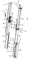
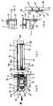
- the holding and pulling device according to FIGS. 1 to 13 is used for fastening and pulling out two pull-out plates 1, 2 accommodated in a kitchen furniture body (not shown). They lie in the inserted position one above the other in the furniture body (FIG. 9) while they are in the pulled-out position Layer (Fig. 1) have completely moved out of the furniture body and lie at the same height one behind the other and connect to each other.
- the holding and pulling device shown has two pull-out guides 3 and 3 ⁇ with pull-out parts designed as telescopic tubes 4 to 7 and 4 ⁇ , 7 ⁇ and two lifting members 8 ⁇ .
- the pull-out guide 3, 3 ⁇ and the lifting links 8 ⁇ are of the same design and are attached to the right and left side walls of the furniture.
- the telescopic tubes of the pull-out guide 3 ⁇ only the outer telescopic tube 4 is shown in FIG. 1 and the innermost telescopic tube 7 ⁇ in FIG. 13.
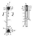
- P front ends 13 ⁇ of the telescopic tubes 7, 7 ⁇ (cf. FIG. 13) are in a first fastening section 14, 14 ⁇ a fastening bracket 15, 15 ⁇ angled inwards at right angles, a profile strip 9, 9 ⁇ of the plate 1, each with a screw 16, 16 ⁇ ( Fig. 8) screwed.
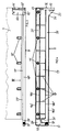
- the profile strips 9, 9 ⁇ are attached to the side edges of the front plate 1 in the pull-out direction P and form a first edge trim. 3 and 4, the profile bar 9 ⁇ is shown in more detail. It is a mirror image of the other profile bar 9.
- the profile bar 9 ⁇ is preferably made of plastic and has stiffening ribs 18 ⁇ on the inside as well as plug pins 19 ⁇ and a longitudinal groove 20 ⁇ .
- the plug pins 19 ⁇ are arranged at the same distance next to each other on a web 23 ⁇ provided in the upper third of the profile strip 9 ⁇ and are pressed into the left side edge 21 ⁇ of the plate 1.
- the height of the profile strips 9, 9 ⁇ is several times greater than the plate thickness (FIG. 5), which is approximately the height of the web 23 ⁇ having the plug pins 19ap. It is bounded at the top and bottom by a stiffening rib 18a ⁇ and 18b ⁇ , which extends essentially over the entire length of the profile bar 9 ⁇ .
- the longitudinal groove 20 ⁇ has approximately the same height as the web 23 ⁇ and is again limited at the top and bottom by stiffening ribs 18a ⁇ and 18b ⁇ .
- the longitudinal groove 20 ⁇ extends at both ends to form a latching and insertion opening 24 ⁇ and 25 ⁇ at right angles upwards or downwards.
- the stiffening rib 18b ⁇ runs U-shaped upwards, while the Stiffening rib 18a ⁇ ends in front of the region of the insertion opening 25 ⁇ in an end section 26 ⁇ bent downward in the shape of a partial circle.
- a bolt-shaped guide member or driver 27 ⁇ of a second cladding of the rear plate 2, designed as a profile strip 28 ⁇ , can be inserted into the longitudinal groove 20 ⁇ via the open opening 25offen (FIG.
- the plate 2 like the plate 1, also has a profile strip 28 with a driver 27 on the other side edge (FIG. 10).
- the driver 27 is in turn assigned a longitudinal groove 20 in the profile strip 9.
- the assembled profile strips 9, 9 ⁇ with their ends 29, 29 ⁇ having the latching openings 24 ⁇ project beyond the rear edge 30 of the plate 1 in the direction of extraction P.
- a stop buffer 32 ⁇ is arranged for the driver 27 ⁇ .
- the front end of the profile strip 9 ⁇ in the pull-out direction P has a fastening tab 15 ⁇ which is angled inwards at right angles. It consists of a first, external fastening section 33 ⁇ (Fig. 5, 12, 13) and the inwardly connecting fastening section 14 Befest Trents for the end 13 ⁇ of the telescopic tube 7 Teles.
- the fastening section 14 ⁇ has a vertical longitudinal slot 34 ⁇ (Fig. 5), the length of which corresponds to the stroke of the plate 1 when moving out and in of the furniture body.
- the other Fastening section 33 ⁇ has a downward-opening push-through opening 35 ⁇ (FIG. 5) for a screw 36 (FIG. 13), with which a holding tab 37 for an end face plate 38 of the plate 1 is fastened to the fastening section 33 ⁇ .
- the retaining tab 37 is screwed to the inside 39 of the panel 38 with screws 40, 41. Its upper end 42 is offset from the panel 38 from the remaining tab portion 43, so that it runs parallel to the panel. With the tab end 42, the holding tab 37 with the panel 38 is inserted into a pocket-like insertion opening 44 of the fastening section 33 ⁇ (FIG. 13).
- the plate 1 lies in the assembled position of the profile strips 9, 9 ⁇ on a rear over the fastening sections 14 ⁇ , 33 ⁇ projecting web 45 (Fig. 3, 4, 5, 12, 13) of the fastening section 33 ⁇ flat.
- the web 45 is approximately at the level of the stiffening rib 18b ⁇ .
- the plate 1 and the profile strips 9, 9 ⁇ form a common flat top.
- the profile strips 28, 28 ⁇ are similar to the profile strips 9, 9 ⁇ . They are preferably made of plastic and have horizontal and vertical stiffening ribs 46, 46 ⁇ . The profile strips 28, 28 ⁇ also have spigots 47, with which they are pressed into the side edges of the plate 2. Both plates 1, 2 are of the same width. In the inserted position of the two plates 1, 2, the two profile strips 9, 9 ⁇ of the front plate 1 in the pull-out direction P lie on the outer sides of the two profile strips 28, 28 ⁇ of the rear plate 2. The thickness of the profile strips 28, 28 ⁇ corresponds approximately to the thickness of the webs 23 ⁇ of the profile strips 9, 9 ⁇ .
- the profile strips 28, 28 ⁇ In inserted position are therefore the profile strips 28, 28 ⁇ below the webs 23 ⁇ , so that the profile strips 28, 28 ⁇ are not only covered outwards by the profile strips 9, 9 ⁇ , but also upwards by the profile strips 9, 9 ⁇ .
- the profile strips 9, 9 ⁇ and 28, 28 ⁇ have a small distance from one another, so that they do not rub against each other when the plates 1, 2 are inserted and removed.
- the profile strips 9, 9 ⁇ are each assigned one of the lifting members 8 ⁇ , which lies in the path of movement of these profile strips.
- the identical lifting members 8 ⁇ , of which only one is shown in the drawings, are preferably plate-like.
- Fig. 1 have the lifting members 8 ⁇ trapezoidal shape with oblique edges 48, 50 and a horizontal edge 49.
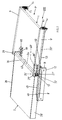
- the front edge 50 in the pull-out direction P forms when inserting the plates 1, 2 a ramp, on which the profile strips 9, 9 ⁇ with a lower rounded corner 51 of its rear end 52 accrue (Fig. 1, 2, 4).
- the plate 1 tilts down from its horizontal position, the screws 16, 16 ⁇ of the telescopic tubes 7, 7 ⁇ sliding in the longitudinal slot 34, 34 ⁇ of the fastening tabs 15, 15 ⁇ upwards.
- the plates 1, 2 can be extended further by pulling the telescopic tubes 7, 7 ⁇ out of the telescopic tubes 6.
- the plates 1, 2 are supported by two guides 60, 60 ⁇ , 61, 61 ⁇ . They each consist of angled rails 60, 60 ⁇ arranged adjacent to the telescopic tubes 4 to 7 and 4 ⁇ , 7 ⁇ and slides 61, 61 ⁇ guided in these, the angled rails forming supports for the plates 1, 2.
- the angle rails 60, 60 ⁇ rest with a horizontal leg 62 on the underside 63 of the plate 2 and are screwed to it (Fig. 2, 10).
- the angle rails 60, 60 ⁇ are attached to the plate 2 so that they protrude almost over half their length over the front plate edge 64 of the plate 2.
- the plate 1 rests on the protruding sections 60a of the angle rails 60, 60 ⁇ .
- the vertically extending legs 65 of the angle rails 60, 60 ⁇ have a horizontally extending longitudinal slot 66, 66 ⁇ , in which the sliders 61, 61 ⁇ are guided.
- the free ends 67, 68, 68 ⁇ of the leg 65 are bent vertically inwards. They each have a preferably part-circular opening 69 (FIG. 10) which open into an enlarged end section 70, 71 of the longitudinal slot 66.
- the maximum width of the openings 69 corresponds to the width of the end sections 70, 71. Via the openings 69 and the end sections 70, 71, the sliders 61, 61 ⁇ can easily be inserted into the longitudinal slot 66, 66 ⁇ .
- the sliding pieces 61, 61 ⁇ preferably consist of a bolt 61a with a roller 61b arranged at the end, a disk or the like.
- the roller 61b lies on the inside of the vertical leg 65 and is screwed onto the bolt 61a with a screw 70a (FIG. 10, 11).
- a buffer 74, 74 ⁇ preferably made of rubber, is arranged in the opening 69.
- the sliders are each screwed into a stop 72, 72 ⁇ (Fig. 8, 10). It is attached to the front edge 73 of the telescopic tube 5.
- the stop pieces 72, 72 ⁇ serve as a stop at the front end of the telescopic tubes 4, 4 ⁇ and when pulled out as a stop for a stop (not shown) of the telescopic tube 6.
- the plate 1 lies in the inserted position above the plate 2 (FIG. 9), the plate 1 being supported via the profile strips 9, 9 ⁇ on the horizontal edges 49 of the lifting members 8 ⁇ and the telescopic tubes 5 to 7, 7 ⁇ in the telescopic tubes 4, 4 ⁇ are retracted.
- the plate 1 has - measured in the pull-out direction P - preferably the same length as the plate 2.
- the plate 1 is offset in the inserted position relative to the plate 2 (FIG. 9), so that it projects forward over the plate 2 and with it its attached panel 38 rests on the front of the furniture body.
- the profile strips 9, 9 ⁇ first slide on the horizontal edges 49 of the lifting members 8 ⁇ .
- the fastening screws 16, 16 'in the longitudinal slots 34, 34' of the fastening tabs 15, 15 'from the lower one shown in FIG slide in the upper position in which they come into contact with the upper end of the slot and limit the swiveling movement. If the plate 1 is now pulled out of the furniture body until it lies with its rear edge 30 in front of the front edge 2a of the plate 2, then the plate 1 also lowers in its rear region until it rests on the upper horizontal legs 62 the angle rails 60, 60 ⁇ rests.
- This lowering movement is achieved in that the profiled strips 9, 9 ⁇ with their rounded corners 51 reach the inclined surfaces 50 of the lifting members 8 ⁇ , so that the plate 1 is lowered at its rearward end in the pull-out direction P when it is pulled out further.
- the plate 1 is in the lowered position at the same height as the immediately adjacent rear plate 2.
- the drivers 27, 27 ⁇ of the profile strips 28, 28 ⁇ of the plate 2 slide in the longitudinal grooves 20, 20 ⁇ of the profile strips 9, 9 ⁇ , while the plate 2 remains in its inserted position. If the plate 1 according to the situation. Fig. 2 has been reached and lowered, the drivers 27, 27 ⁇ of the profile strips 28, 28 ⁇ of the plate 2 enter the locking openings 24 ⁇ of the profile strips 9, 9 ⁇ .
- the plates 1 and 2 are then positively connected to each other in the pull-out direction P, so that when the plate 1 is further pulled out, the plate 2 is also pulled out, the profiled strips 28, 28 'with their undersides 31 on the horizontal legs 10, 10' of the mounting bracket 11, 11 ' slide.
- the plate 1 lowers until it rests with its rear part on the angle rails 60, 60 ⁇ , which are attached to the rear plate 2.
- the rear plate 2 is not directly connected to one of the telescopic tubes, but only via the positive connection 24 ⁇ , 27 ⁇ of the profile strips 9, 9 ⁇ , 28, 28 ⁇ with the telescopic tubes 7, 7 ⁇ .
- the plate 2 is carried over the described positive connection 24 ⁇ , 27 ⁇ from the front plate 1. Since the angle rails 60, 60 ⁇ are attached to the rear plate 2, they are moved to the same extent, so that the front plate 1 is always properly supported.
- the angle rails 60, 60 ⁇ are shifted relative to the sliders 61, 61 ⁇ , which are fastened to the telescopic tubes 5 via the stop pieces 72, 72 ⁇ .
- the angle rails 60, 60 ⁇ and thus the two plates 1, 2 can be displaced until the sliders 61, 61 ⁇ come to rest on the leg end 67 in the pull-out direction P or on the stop buffer 74, 74 ⁇ arranged there (FIG. 11 ). Then the maximum extension path of the plates 1, 2 is reached.
- the plate 2 is in this position almost completely outside the furniture body, so that the bearing surface of the plates 1, 2 can be fully used.
- the angle rails 60, 60 Gleit and the sliding pieces 61, 61 ⁇ the greatest possible extension path of the panels 1, 2 is ensured with a minimal depth of the furniture body.
- the plate 1 In order to move the plates 1, 2 back into the furniture body, the plate 1 is pushed back in the direction of the arrow P ⁇ in FIG.
- the angle rails 60, 60 ⁇ first slide backwards on the sliders 61, 61 ⁇ until they come to rest on the front leg ends 68, 68 ⁇ of the angle rails or the stop buffers 74, 74 ⁇ arranged there in the direction of extension P.
- the Telescopic tubes 7, 7 ⁇ moved into the telescopic tubes 6.
- the telescopic tubes 5 are pushed into the telescopic tubes 4, 4 ⁇ until the profile strips 9, 9 ⁇ with their rear ends 51 run on the inclined edges 50 of the lifting elements 8 ⁇ (FIG. 2).
- the rear end of the plate 1 is raised by the lifting members 8 ⁇ until this end is above the plate 2 (Fig. 2).
- the drivers 27, 27 ⁇ of the profile strips 28, 28 ⁇ get into the area of the longitudinal grooves 20 ⁇ of the profile strips 9, 9 ⁇ .
- Fig. 2 takes the plate 2 in its inserted position.
- the drivers 27, 27 ⁇ of the profiled strips 28, 28 ⁇ slide in the longitudinal grooves 20, 20 ⁇ of the profiled strips 9, 9 ⁇ .
- the plate 1 tilts under its own weight into the horizontal position, with its profile strips 9, 9 ⁇ resting on the horizontal edges 49 of the lifting members 8 ⁇ .
- the panel 38 fastened to the fastening tabs 15, 15 ⁇ of the profiled strips 9, 9ckt covers the insertion opening in the furniture body in the inserted position of the panels 1, 2.
- the panel 38 can be easily attached to the mounting tabs with the two retaining tabs 37. Its cranked end 42 can be inserted from below into the pocket-shaped plug-in openings 44 of the fastening sections 33 ⁇ , as a result of which the diaphragm is already aligned transversely to the profiled strips 9, 9 ⁇ .
- the elongated push-through openings 35 ⁇ then allow the aperture 38 to be aligned in the vertical direction.
Landscapes
- Holders For Apparel And Elements Relating To Apparel (AREA)
- Tables And Desks Characterized By Structural Shape (AREA)
- Electrical Discharge Machining, Electrochemical Machining, And Combined Machining (AREA)
- Forklifts And Lifting Vehicles (AREA)
- Forms Removed On Construction Sites Or Auxiliary Members Thereof (AREA)
- Securing Of Glass Panes Or The Like (AREA)
- Exposure And Positioning Against Photoresist Photosensitive Materials (AREA)
- Escalators And Moving Walkways (AREA)
- Sheets, Magazines, And Separation Thereof (AREA)
- Forming Counted Batches (AREA)
- Assembled Shelves (AREA)
Claims (10)
- Dispositif de support et d'extraction pour extraire au moins un premier plateau (1) et un second plateau (2), par exemple une tablette ou un plan de travail, d'un logement en particulier d'un corps de meuble de cuisine, dans lequel les plateaux sont disposés l'un au-dessus de l'autre dans la position rentrée et l'un derrière l'autre au même niveau dans la position tirée, comprenant un guidage d'extraction (3, 3') pour les plateaux montés sur le logement et un élément de levage (8') pour l'un des deux plateaux, et au moins un élément d'entraînement (27, 27') par lequel les plateaux peuvent être couplés de manière rigide en traction lors de l'extraction, caractérisé en ce que l'élément d'entraînement (27, 27') est prévu sur un premier habillage latéral (28, 28') de l'un des deux plateaux (2) et en prise avec un second habillage latéral (9, 9') de l'autre plateau (1), et que le second habillage (9, 9') coopère avec l'élément de levage (8') lors de l'introduction et respectivement de l'extraction du plateau (1).
- Dispositif selon la revendication 1, caractérisé en ce qu'au moins l'un des habillages et de préférence les deux habillages (9, 9'; 28, 28') est (sont) conformé(s) en baguette(s) réalisée(s) de préférence en matière plastique.
- Dispositif selon l'une des revendications 1 ou 2, caractérisé en ce que le second habillage (9,9') dépasse vers le bas du bord (21') du plateau (1) et comprend dans la section en saillie une rainure longitudinale (20, 20') pour l'élément d'entraînement (27, 27') laquelle s'étend dans la direction d'extraction et d'introduction (P et P'), et que le premier habillage (28, 28') est muni à son extrémité antérieure dans la direction d'extraction (P) de l'élément d'entraînement (27, 27') dépassant vers l'extérieur, de préférence un boulon ou une broche.
- Dispositif selon l'une des revendications 1 à 3, caractérisé en ce que, à son extrémité postérieure dans la direction d'extraction (P), la rainure longitudinale (20') du second habillage (9, 9,) est coudée vers le haut pour former une ouverture d'encliquetage (24') pour l'élément d'entraînement (27, 27'), et que l'extrémité de la rainure longitudinale (20') du second habillage (9, 9'), antérieure dans la direction d'extraction (P), est ouverte vers le bas pour former une ouverture d'introduction (25') pour l'élément d'entraînement (27, 27').
- Dispositif selon l'une des revendications 1 à 4, caractérisé en ce que l'élément de levage (8') est conformé en plaque avec un contour sensiblement trapézoïdal et qu'il présente un bord oblique comme rampe (50) pour le second habillage (9, 9').
- Dispositif selon l'une des revendications 1 à 5, caractérisé en ce que, à son extrémité (15, 15') antérieure dans la direction d'extraction (P), le second habillage (9, 9') est coudé vers l'intérieur en forme de patte et que l'extrémité (15, 15') coudée en patte comporte deux sections de fixation (14, 14' et 33') juxtaposées transversalement à la direction d'extraction (P) pour un élément de fixation (37) d'un cache (38) et un élément d'extraction (7, 7') du guidage d'extraction (3, 3').
- Dispositif selon la revendication 6, caractérisé en ce que la section de fixation (33') située plus à l'extérieur présente une ouverture d'emboîtement (44) pour une extrémité (42) de l'élément de fixation (37) du cache (38), que l'autre section de fixation (14, 14') présente une fente longitudinale (34, 34') d'extension sensiblement verticale pour un élément de fixation (16, 16') de l'un des éléments d'extraction (7, 7'), et que la longueur de la fente longitudinale (34, 34') correspond au moins à la course de l'un des plateaux, de préférence à celle du plateau antérieur (1).
- Dispositif selon l'une des revendications 1 à 7, caractérisé en ce que sur le plateau (2) postérieur dans la direction d'extraction (P) est fixé au moins un support (60, 60') pour l'extrémité postérieure du plateau antérieur (1), et que le support (60, 60') peut être déplacé par rapport à une partie du guidage d'extraction (3, 3').
- Dispositif selon l'une des revendications 1 à 8, dans lequel le guidage d'extraction est constitué par un guidage télescopique avec des tubes télescopiques, caractérisé en ce que sur un tube télescopique (5) est monté un coulisseau 61, 61'), de préférence un boulon ou une vis, qui dépasse au travers d'une fente longitudinale (66, 66') du support (60, 60') orientée dans la direction d'extraction (P), et que la longueur de la fente longitudinale (66) correspond à la distance d'extraction de l'un des éléments extractibles (7, 7'), de préférence tubulaire, qui peut être déplacé dans un tube télescopique intérieur (6).
- Dispositif selon la revendication 9, caractérisé en ce que la fente longitudinale (66) du support (60, 60') débouche dans des ouvertures d'introduction (69) élargies pour le coulisseau (61, 61'), de préférence ménagées dans des extrémités (67, 68, 68') du support (60, 60') coudées orthogonalement vers l'intérieur, et que sur les bords ouverts des ouvertures d'introduction (69) sont montés des tampons de butée (74, 74') pour le coulisseau (61, 61').
Priority Applications (1)
| Application Number | Priority Date | Filing Date | Title |
|---|---|---|---|
| AT88101278T ATE77540T1 (de) | 1987-02-04 | 1988-01-29 | Halte-und auszieheinrichtung. |
Applications Claiming Priority (2)
| Application Number | Priority Date | Filing Date | Title |
|---|---|---|---|
| DE3703249A DE3703249C2 (de) | 1987-02-04 | 1987-02-04 | Halte- und Auszieheinrichtung |
| DE3703249 | 1987-02-04 |
Publications (3)
| Publication Number | Publication Date |
|---|---|
| EP0277601A2 EP0277601A2 (fr) | 1988-08-10 |
| EP0277601A3 EP0277601A3 (en) | 1990-02-14 |
| EP0277601B1 true EP0277601B1 (fr) | 1992-06-24 |
Family
ID=6320150
Family Applications (1)
| Application Number | Title | Priority Date | Filing Date |
|---|---|---|---|
| EP88101278A Expired - Lifetime EP0277601B1 (fr) | 1987-02-04 | 1988-01-29 | Dispositif de support et de coulissement |
Country Status (4)
| Country | Link |
|---|---|
| EP (1) | EP0277601B1 (fr) |
| AT (1) | ATE77540T1 (fr) |
| DE (2) | DE3703249C2 (fr) |
| ES (1) | ES2032875T3 (fr) |
Families Citing this family (2)
| Publication number | Priority date | Publication date | Assignee | Title |
|---|---|---|---|---|
| DE4016918A1 (de) * | 1990-05-25 | 1991-11-28 | Miele & Cie | Einbaubackofen mit einem den herd umgebenden moebelgehaeuse |
| DE29513880U1 (de) * | 1995-08-30 | 1996-08-22 | Hymer AG, 88339 Bad Waldsee | Theke mit Thekenverbreiterung |
Family Cites Families (4)
| Publication number | Priority date | Publication date | Assignee | Title |
|---|---|---|---|---|
| DE2263073C2 (de) * | 1972-12-22 | 1982-11-25 | Robert Krause KG Zweigniederlassung Weilheim/Teck, 7315 Weilheim | Ausziehbeschlag für eine erste Platte und eine zweite Platte, wie einer Tisch- oder Arbeitsplatte |
| DE2646282C2 (de) * | 1976-10-14 | 1986-07-10 | Robert Krause Kg Zweigniederlassung Weilheim-Teck, 7315 Weilheim | Vorrichtung zum Ausziehen von zwei Platten, wie Tisch- oder Arbeitsplatten, aus einem Träger, wie einem Küchenmöbel |
| DE3025958C2 (de) * | 1980-07-09 | 1982-10-28 | Hailo-Werk Rudolf Loh Gmbh & Co Kg, 6342 Haiger | Ausziehtisch für Möbel, insbesondere Küchenmöbel |
| DE3516957A1 (de) * | 1985-05-10 | 1986-11-13 | Alfred Grass GmbH Metallwarenfabrik, Höchst, Vorarlberg | Einfach- und voll-auszug fuer schubladen |
-
1987
- 1987-02-04 DE DE3703249A patent/DE3703249C2/de not_active Expired - Fee Related
-
1988
- 1988-01-29 AT AT88101278T patent/ATE77540T1/de not_active IP Right Cessation
- 1988-01-29 DE DE8888101278T patent/DE3872261D1/de not_active Expired - Fee Related
- 1988-01-29 EP EP88101278A patent/EP0277601B1/fr not_active Expired - Lifetime
- 1988-01-29 ES ES198888101278T patent/ES2032875T3/es not_active Expired - Lifetime
Also Published As
| Publication number | Publication date |
|---|---|
| DE3703249A1 (de) | 1988-08-18 |
| EP0277601A3 (en) | 1990-02-14 |
| DE3872261D1 (de) | 1992-07-30 |
| DE3703249C2 (de) | 1996-05-15 |
| ATE77540T1 (de) | 1992-07-15 |
| EP0277601A2 (fr) | 1988-08-10 |
| ES2032875T3 (es) | 1993-03-01 |
Similar Documents
| Publication | Publication Date | Title |
|---|---|---|
| EP0421458B1 (fr) | Tiroir | |
| EP2642897B1 (fr) | Dispositif d'accouplement pour tiroir | |
| EP0706012B1 (fr) | Four de cuisson | |
| EP0700649A1 (fr) | Dispositif de fermeture pour tiroirs | |
| EP3745918B1 (fr) | Rail de chargement pour une glissière télescopique de tiroir | |
| AT929U1 (de) | Schubladenführung | |
| EP0011675A1 (fr) | Glissière pour tiroirs ou similaires | |
| EP0041616B1 (fr) | Glissière télescopique pour support, tel que tiroirou similaire | |
| DE102013018063A1 (de) | Teleskopförderband | |
| DE4227585A1 (de) | Geschirrspülmaschine mit höhenverstellbarem Geschirrkorb | |
| EP1846711B1 (fr) | Appareil a refroidir dote d'un porte-produits a refroidir coulissant | |
| EP1513429A1 (fr) | Ensemble pour relier un encadrement de tiroir au fond de tiroir | |
| EP3108191B1 (fr) | Appareil frigorifique comprenant un espace intérieur avec support coulissant couplé aux mouvements du récipient de stockage | |
| DE3703249C2 (de) | Halte- und Auszieheinrichtung | |
| DE3135222C2 (fr) | ||
| AT410629B (de) | Teleskop-schrankauszug | |
| DE4304074C2 (de) | Kühlgerät, insbesondere Haushalt-Kühlschrank | |
| DE19828718A1 (de) | Rasteinrichtung zum lösbaren Befestigen von Schubkästen, Auszügen, Schüben o. dgl. an einer Führungsschiene | |
| EP0523424B1 (fr) | Dispositif de guidage pour tiroir | |
| DE3221926C2 (de) | Auszieheinrichtung für einen mit einem Möbelkorpus versehenen Schrank | |
| AT393350B (de) | Schubladenauszug | |
| AT390357B (de) | Auszieheinrichtung fuer einen schrank | |
| DE10022084A1 (de) | Laufschiene für Schubkästen | |
| AT390359B (de) | Schubladenauszug als einfachauszug | |
| DE2646282C2 (de) | Vorrichtung zum Ausziehen von zwei Platten, wie Tisch- oder Arbeitsplatten, aus einem Träger, wie einem Küchenmöbel |
Legal Events
| Date | Code | Title | Description |
|---|---|---|---|
| PUAI | Public reference made under article 153(3) epc to a published international application that has entered the european phase |
Free format text: ORIGINAL CODE: 0009012 |
|
| AK | Designated contracting states |
Kind code of ref document: A2 Designated state(s): AT BE CH DE ES FR GB IT LI NL SE |
|
| PUAL | Search report despatched |
Free format text: ORIGINAL CODE: 0009013 |
|
| AK | Designated contracting states |
Kind code of ref document: A3 Designated state(s): AT BE CH DE ES FR GB IT LI NL SE |
|
| 17P | Request for examination filed |
Effective date: 19900629 |
|
| 17Q | First examination report despatched |
Effective date: 19911009 |
|
| GRAA | (expected) grant |
Free format text: ORIGINAL CODE: 0009210 |
|
| AK | Designated contracting states |
Kind code of ref document: B1 Designated state(s): AT BE CH DE ES FR GB IT LI NL SE |
|
| REF | Corresponds to: |
Ref document number: 77540 Country of ref document: AT Date of ref document: 19920715 Kind code of ref document: T |
|
| REF | Corresponds to: |
Ref document number: 3872261 Country of ref document: DE Date of ref document: 19920730 |
|
| ET | Fr: translation filed | ||
| ITF | It: translation for a ep patent filed | ||
| GBT | Gb: translation of ep patent filed (gb section 77(6)(a)/1977) | ||
| REG | Reference to a national code |
Ref country code: ES Ref legal event code: FG2A Ref document number: 2032875 Country of ref document: ES Kind code of ref document: T3 |
|
| PLBE | No opposition filed within time limit |
Free format text: ORIGINAL CODE: 0009261 |
|
| STAA | Information on the status of an ep patent application or granted ep patent |
Free format text: STATUS: NO OPPOSITION FILED WITHIN TIME LIMIT |
|
| 26N | No opposition filed | ||
| EAL | Se: european patent in force in sweden |
Ref document number: 88101278.5 |
|
| PGFP | Annual fee paid to national office [announced via postgrant information from national office to epo] |
Ref country code: GB Payment date: 19970114 Year of fee payment: 10 |
|
| PGFP | Annual fee paid to national office [announced via postgrant information from national office to epo] |
Ref country code: SE Payment date: 19971219 Year of fee payment: 11 |
|
| PGFP | Annual fee paid to national office [announced via postgrant information from national office to epo] |
Ref country code: ES Payment date: 19980112 Year of fee payment: 11 |
|
| PGFP | Annual fee paid to national office [announced via postgrant information from national office to epo] |
Ref country code: FR Payment date: 19980115 Year of fee payment: 11 |
|
| PG25 | Lapsed in a contracting state [announced via postgrant information from national office to epo] |
Ref country code: GB Free format text: LAPSE BECAUSE OF NON-PAYMENT OF DUE FEES Effective date: 19980129 |
|
| PGFP | Annual fee paid to national office [announced via postgrant information from national office to epo] |
Ref country code: CH Payment date: 19980218 Year of fee payment: 11 |
|
| PGFP | Annual fee paid to national office [announced via postgrant information from national office to epo] |
Ref country code: AT Payment date: 19980527 Year of fee payment: 11 |
|
| PGFP | Annual fee paid to national office [announced via postgrant information from national office to epo] |
Ref country code: BE Payment date: 19980615 Year of fee payment: 11 |
|
| PGFP | Annual fee paid to national office [announced via postgrant information from national office to epo] |
Ref country code: NL Payment date: 19980630 Year of fee payment: 11 |
|
| GBPC | Gb: european patent ceased through non-payment of renewal fee |
Effective date: 19980129 |
|
| PG25 | Lapsed in a contracting state [announced via postgrant information from national office to epo] |
Ref country code: AT Free format text: LAPSE BECAUSE OF NON-PAYMENT OF DUE FEES Effective date: 19990129 |
|
| PG25 | Lapsed in a contracting state [announced via postgrant information from national office to epo] |
Ref country code: SE Free format text: LAPSE BECAUSE OF NON-PAYMENT OF DUE FEES Effective date: 19990130 Ref country code: ES Free format text: LAPSE BECAUSE OF NON-PAYMENT OF DUE FEES Effective date: 19990130 |
|
| PG25 | Lapsed in a contracting state [announced via postgrant information from national office to epo] |
Ref country code: LI Free format text: LAPSE BECAUSE OF NON-PAYMENT OF DUE FEES Effective date: 19990131 Ref country code: CH Free format text: LAPSE BECAUSE OF NON-PAYMENT OF DUE FEES Effective date: 19990131 Ref country code: BE Free format text: LAPSE BECAUSE OF NON-PAYMENT OF DUE FEES Effective date: 19990131 |
|
| BERE | Be: lapsed |
Owner name: ROBERT KRAUSE G.M.B.H. & CO. K.G. Effective date: 19990131 |
|
| PG25 | Lapsed in a contracting state [announced via postgrant information from national office to epo] |
Ref country code: NL Free format text: LAPSE BECAUSE OF NON-PAYMENT OF DUE FEES Effective date: 19990801 |
|
| REG | Reference to a national code |
Ref country code: CH Ref legal event code: PL |
|
| PG25 | Lapsed in a contracting state [announced via postgrant information from national office to epo] |
Ref country code: FR Free format text: LAPSE BECAUSE OF NON-PAYMENT OF DUE FEES Effective date: 19990930 |
|
| REG | Reference to a national code |
Ref country code: FR Ref legal event code: ST |
|
| REG | Reference to a national code |
Ref country code: ES Ref legal event code: FD2A Effective date: 20010910 |
|
| PG25 | Lapsed in a contracting state [announced via postgrant information from national office to epo] |
Ref country code: IT Free format text: LAPSE BECAUSE OF NON-PAYMENT OF DUE FEES Effective date: 20050129 |
|
| PGFP | Annual fee paid to national office [announced via postgrant information from national office to epo] |
Ref country code: DE Payment date: 20050330 Year of fee payment: 18 |
|
| PG25 | Lapsed in a contracting state [announced via postgrant information from national office to epo] |
Ref country code: DE Free format text: LAPSE BECAUSE OF NON-PAYMENT OF DUE FEES Effective date: 20060801 |