EP0277623A2 - Elément et appareil pour la détection de défauts internes dans un appareil électrique à isolement gazeux - Google Patents
Elément et appareil pour la détection de défauts internes dans un appareil électrique à isolement gazeux Download PDFInfo
- Publication number
- EP0277623A2 EP0277623A2 EP88101413A EP88101413A EP0277623A2 EP 0277623 A2 EP0277623 A2 EP 0277623A2 EP 88101413 A EP88101413 A EP 88101413A EP 88101413 A EP88101413 A EP 88101413A EP 0277623 A2 EP0277623 A2 EP 0277623A2
- Authority
- EP
- European Patent Office
- Prior art keywords
- electrical apparatus
- gas
- detecting
- fault detection
- internal fault
- Prior art date
- Legal status (The legal status is an assumption and is not a legal conclusion. Google has not performed a legal analysis and makes no representation as to the accuracy of the status listed.)
- Withdrawn
Links
Images







Classifications
-
- G—PHYSICS
- G01—MEASURING; TESTING
- G01N—INVESTIGATING OR ANALYSING MATERIALS BY DETERMINING THEIR CHEMICAL OR PHYSICAL PROPERTIES
- G01N27/00—Investigating or analysing materials by the use of electric, electrochemical, or magnetic means
- G01N27/02—Investigating or analysing materials by the use of electric, electrochemical, or magnetic means by investigating impedance
- G01N27/04—Investigating or analysing materials by the use of electric, electrochemical, or magnetic means by investigating impedance by investigating resistance
- G01N27/041—Investigating or analysing materials by the use of electric, electrochemical, or magnetic means by investigating impedance by investigating resistance of a solid body
-
- G—PHYSICS
- G01—MEASURING; TESTING
- G01N—INVESTIGATING OR ANALYSING MATERIALS BY DETERMINING THEIR CHEMICAL OR PHYSICAL PROPERTIES
- G01N17/00—Investigating resistance of materials to the weather, to corrosion, or to light
Definitions
- the present invention relates to an element and a device for detecting internal faults in an electrical apparatus charged with an insulating gas. More particularly, the present invention relates to a device for detecting internal faults in an electrical apparatus charged with an insulating gas such as SF6 gas, by using the fact that the presence of internal faults in the insulating gas charged electrical apparatus can be detected by the generation of decomposed SF6 gas.
- an insulating gas such as SF6 gas
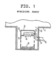
- Fig. 1 is a partial cross-sectional view illustrating a conventional internal fault detection device for an insulating gas charged electrical apparatus incorporating an internal fault element, as disclosed in, for instance, Japanese Patent Publication No. 57-38091.
- a hermetic grounded metal vessel 1 is provided in a part of an electrical apparatus (not shown) charged with an insulating gas such as SF6, the hermetic grounded metal vessel 1 also being filled with SF6 denoted by 2.
- a detection element supporting container 3 is provided substantially in the center of the hermetic grounded metal vessel 1.
- An internal fault detection element 4 constituted by a thin aluminum (Al) metal plate with a thickness of, for instance, about 5 ⁇ m is supported inside the element supporting container 3 in an upper portion thereof.
- a plurality of gas permeable through holes 7 are provided on side surfaces of the element supporting container 3.
- external conductors 8 connected to an external circuit are provided on the outside of the hermetic grounded metal vessel 1. Both ends of these external conductors 8 are electrically connected to the internal fault detection element 4 via insulated terminals 9 that pass air-tightly through a side wall portion of the hermetic grounded metal vessel 1 as well as via internal conductors 5 disposed inside the hermetic grounded metal vessel 1.
- the conventional internal fault detection device is constructed as described above, and when a fault, such as a discharge, occurs in the hermetic grounded metal vessel 1, the SF6 2 is decomposed to produce an active low fluorinated sulfur compound gas of SF4, SOF2, HF, etc., i.e., a decomposed SF6 gas.
- This decomposed SF6 gas enters the inside of the element supporting container 3 through the through holes 7 provided in the side surfaces thereof and is converted into HF upon reacting with a trace amount of water which is present in the SF6 2 in the container 3, and with water and the like which is released from the substance 6 containing crystallized water.
- the internal fault detection element 4 produces AlF3 due to the following reaction that takes place inside the container 3 which is filled with an atmosphere containing both the decomposed SF6 gas and water: Al + 3HF ⁇ AlF3 + 3/2H2
- the internal fault detection element 4 is formed of an Al metal plate, the reaction will not proceed adequately unless high-concentration SF6 gas is used. Therefore, fault detection is only possible in cases where a high-concentration decomposed SF6 gas is present, as in the case of a ground fault, but the detection speed is low. However, fault detection cannot be effected sufficiently in cases where the concentration of the decomposed SF6 gas is low as in the case of a partial discharge or local heating. Further, there arises a problem in that a material which releases water upon coming into contact with the decomposed SF6 gas, such as the crystallized water-containing substance 6, is required.
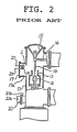
- Fig. 2 is a cross-sectional view schemetically illustrating another device for detecting internal faults in an insulating gas charged electrical apparatus which is disclosed in Japanese Utility Model Laid-Open No. 61-40657.
- a hermetic vessel 11 for an electrical apparatus charged with an insulating gas, such as SF6 is provided with a movable contactor 12, a nozzle 13 provided such as to surround this movable contactor 12, a fixed contactor 14 into which the movable contactor 12 comes into contact and from which it moves away, a high-voltage conductor 16 connected to the fixed contactor 14, and a spacer 15 supporting the high-voltage conductor 16.
- the hermetic vessel 11 is filled with SF6 2.
- An opening 17a of the hermetic vessel 11 is provided with a flange cover 17, on which a decomposed SF6 gas detection portion 19 having an internal fault detection element is provided.
- a signal from the decomposed gas detection portion 19 is supplied to an external circuit (not shown) by means of conductors 20.
- a gas pipe 21a for introducing the SF6 gas 2 into the hermetic vessel 11 is connected to a side pipe 21b of the hermetic vessel 11 at a gas pipe jointing portion 21.
- the decomposed SF6 gas resulting from the generation of a discharge or local heating in a conducting contact portion inside the SF6 gas charged electrical apparatus moves to the decomposed SF6 gas detection portion 19 by means of convection and diffusion, and reacts with a sensitive material disposed on the decomposed SF6 detection portion 19, thereby causing a change in the electrical properties thereof.
- a signal representing this change in electrical properties is fetched via the conductors 20 by a signal processing section (not shown), which in turn issues an alarm indicating that a fault is present in the electrical apparatus.
- this decomposed SF6 gas detection portion 19 When this decomposed SF6 gas detection portion 19 is installed in an existing insulating gas charged electrical apparatus which is not provided with a decomposed SF6 gas detection portion, additional machining must be carried out so that the decomposed SF6 gas detection portion 19 can be installed on the flange cover 17.
- the decomposed SF6 gas detection portion 19 is conventionally fixed to the inner side of the flange cover 17, as shown in Fig. 2. Accordingly, there have been problems in that the flange of an existing insulating gas charged electrical apparatus must be machined or modified during checkups or the like so as to allow the installation of the decomposed SF6 gas detection portion 19.
- an object of the present invention is to provide an internal fault detection element which exhibits high response characteristics by making a quick response even to a low-concentration decomposed SF6 gases, and which is capable of detecting at an early stage faults such as discharge, local heating, etc. occurring in an electrical apparatus, thereby solving the problems of the prior art.
- Another object of the present invention is to provide an internal fault detecting device for use in an insulating gas charged electrical apparatus which allows a decomposed SF6 gas detection portion to be readily installed without requiring any particular machining or modification of an existing insulating gas charged electrical apparatus.
- Still another object of the present invention is to provide an internal fault detection device which comprises a photoelectric conversion section for converting a change in a current caused by a change in resistance of an internal fault detection element into an optical signal, and a signal processing section for processing the optical signal sent from the photoelectric conversion section via an optical fiber.
- This apparatus provides the advantages of high insulation, high pressure resistance, non-inductiveness, low loss, lightweight, and safety that are peculiar to optical fibers, and makes it possible to effect remote monitoring safely at high speed and with high precision even in adverse environments where high electromagnetic fields or the like exist, for which remote monitoring has been difficult with a conventional apparatus.
- an element for detecting internal faults in an insulating gas charged electrical apparatus comprising: a substrate formed of a non-conductive material and disposed in an electrical apparatus which is charged with an insulating gas; a pair of electrodes disposed on the substrate in a spaced apart relationship; and a thin metal film disposed on the substrate so as to extend over the electrodes for electrical connection therebetween, the film being formed of a material which is highly reactive with decomposed components of the insulating gas which are produced when the electrical apparatus internally fails, the film being adapted to change its electrical resistance by reaction with the decomposed gas components.
- a device for detecting internal faults in an insulating gas charged electrical apparatus comprising: an internal fault detection element disposed in the electrical apparatus charged with an insulating gas for detecting an internal fault in the electrical apparatus, the element being adapted to change its electrical resistance by reaction with decomposed components of the insulating gas which are produced when the electrical apparatus fails, the element having a pair of first and second electrodes; a current supplying means connected to the first electrode of the internal fault detection element for supplying current to the element; a photoelectric conversion means connected to the second electrode of the internal fault detection element for converting a change in the magnitude of the current output from the second electrode into an optical signal; and a signal processing means connected to the photoelectric conversion means for processing the optical signal supplied from the optical conversion means via an optical fiber.
- Fig. 3A is a plan view of an internal fault detection element 30 in accordance with the present invention
- Fig. 3B is a cross-sectional view taken along the line B-B of Fig. 3A.
- the internal fault detection element 30 comprises a substrate 31 formed of, for instance, sintered Al2O3; electrodes, such as gold (Au) electrodes 32, disposed on both sides of the surface of the substrate 31; and a flat metal film, such as a thin Ag film 33 disposed on the center of the surfaces of the Au electrodes 32 in such a manner as to span the Au electrodes 32.
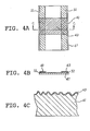
- Fig. 4A is a plan view of another internal fault detection element 40 in accordance with the present invention
- Fig. 4B is a cross-sectional view taken along the line C-C of Fig. 4A
- Fig. 4C is an enlarged cross-sectional view of another internal fault detection element as shown in Figs. 4A and 4B.
- Figs. 4A and 4B are plan views of another internal fault detection elements 40 in accordance with the present invention
- Fig. 4B is a cross-sectional view taken along the line C-C of Fig. 4A
- Fig. 4C is an enlarged cross-sectional view of another internal fault detection element as shown in Figs. 4A and 4B.
- Figs. 4A is a plan view of another internal fault detection element 40 in accordance with the present invention
- Fig. 4B is a cross-sectional view taken along the line C-C of Fig. 4A
- Fig. 4C is an enlarged cross-sectional view of another internal fault detection
- the internal fault detection element 40 comprises a substrate 41 having a multiplicity of fine projections with a thickness of a few ⁇ m to several tens of ⁇ m and formed of, for instance, sintered Al2O3 obtained by sintering Al2O3 powders; electrodes, such as Au electrodes 42 disposed on both sides of the surface of the substrate 41; and a thin metal film, e.g. a thin Ag film 43 provided so as to cover an exposed surface of the substrate 41 and the Au electrodes 42.
- the internal fault detection element 30 or 40 is provided on a flange 51 disposed in a hermetic grounded vessel 50 which is installed in an SF6 charged electric apparatus (not shown), as shown, for instance, in Fig. 5, and is exposed to the SF6 gas 2.
- Such an internal fault detection element 30 or 40 is electrically connected to an external circuit (not shown) via internal conductors 52, insulating sealed terminals 53 and external conductors 54.
- the SF6 gas 2 is decomposed to generate an active decomposed SF6 gas such as SF4 or SOF2.
- This decomposed SF6 gas produces HF upon reacting with a trace amount of water contained in the SF6 2.
- the HF thus produced moves by natural convection and diffusion and reaches the surface of the internal fault detection device 30 or 40, where the HF reacts with the thin Ag film 33 or 43, thereby producing AgF as follows: Ag + HF ⁇ AgF + 1/2H2
- the thin Ag film 33 or 43 is converted into a thin AgF film, the value of its resistance changes. Therefore, it is possible to detect a fault such as a discharge occurring inside the SF6 charged electrical apparatus by monitoring this change in the resistance value by an external circuit (not shown) via the external conductors 54 for the internal fault detection device 30 or 40.
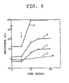
- Fig. 6 illustrates the change in resistance value as a function of time when the internal fault device 30 having the arrangement as shown in Fig. 3A or 3B is exposed to the SF 4 (concentration: 1%) at room temperature under atmospheric pressure.
- curves A , B and C show the results of measurement of the internal fault detection element 30 in which thin Ag films 33 having thicknesses of 10 nm, 30 nm and 100 nm respectively were formed by, for instance, sputtering.
- Curve D shows, by way of comparison, the results of measurement of the conventional internal fault detection element 4 using the Al plate with a thickness of 5 ⁇ m.
- the symbol ⁇ represents the time when the SF4 was introduced.
- the internal fault detection element 30 in the three respective cases of 10 nm to 100 nm exhibited greater response within a shorter time than that of the internal fault detection element 4, i.e., the comparative example. Accordingly, at the time of the occurrence of a ground fault or the like in which the concentration of the decomposed SF6 gas is high, it is possible to detect the internal fault with considerably higher sensitivity.
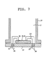
- Fig. 7 shows a partial cross-sectional view illustrating the hermetic grounded metal vessel 50 in which the internal fault detection element 30 or 40 is provided on a temperature control device, e.g. an electron refrigeration device 55.
- a temperature control device e.g. an electron refrigeration device 55.
- reference numerals 2, 30, 40, 50, 51, 52, 53 and 54 denote the same or corresponding parts as those shown in Fig. 5.
- the internal fault detection element 30 or 40 is disposed on one surface of the electronic regrigeration device 55, and the other surface of the electronic refrigeration device 55 is disposed in such a manner as to be in contact with the inner wall surface of the hermetic grounded metal vessel 50.
- conductors 56 from a power source for heating or cooling the electronic refrigeration device 55 are connected to the electronic refrigeration device 55.
- the electronic refrigeration device 55 has a high-temperature side surface and a low-temperature side surface, and the internal fault detection element 30 or 40 can be heated by being disposed on the high-temperature side surface.
- the internal fault detection device 30 or 40 is heated, the sensitivity of the thin Ag film 33 or 43 is further improved. Consequently, the detection at an early stage of such faults as partial discharge and local heating in the SF6 charged electrical apparatus becomes even easier than in cases where the internal fault detection element 30 or 40 is not heated, even in low concentration decomposed SF6 gas.
- Fig. 8 shows a change in resistance value as a function of time when the internal fault detection element 30 having the arrangement as shown in Fig. 7 is exposed to SF4 (concentration: 100 ppm) under atmospheric pressure.
- curves E , F and G show the results of measurement at room temperature of internal fault detection elements 30, in which thin Ag films 33 having thicknesses of 10 nm, 30 nm and 100 nm respectively were formed by, for instance, sputtering.
- Curve H shows the results measured when an electronic refrigeration device 55 having a thin Ag film 33 with a thickness of 100nm formed thereon by, for instance, sputtering, was heated to 80°C.
- the symbol ⁇ denotes the time when the SF4 was introduced.
- the sensitivity was not so high when the internal fault detection element 30 with a thin Ag film having a relatively large thickness of 100nm was used. However, sufficient sensitivity was obtained when the internal fault detection element 30 was heated. Hence, it can be seen that even a decomposed SF6 gas with a very low concentration can be detected. Furthermore, since the sensitivity becomes higher by heating the internal fault detection element 30, it is possible to use a thin Ag film 33 having a thickness of 100nm or more.
- Ag is used as the material for the thin metal film 33 or 43, however, any metal may be used if it is capable of forming a thin film of low resistance and produces fluorides, sulfides, etc. which reduced their conductivity upon coming into contact with a decomposed SF6 gas.
- the high-temperature side of the electronic refrigeration device 55 was used as the device for controlling the temperature of the element 30 or 40.
- the internal fault detection element 30 or 40 is cooled below the dew point of the SF6 gas 2 so as to condense or concentrate water and decomposed SF6 gas on the surface and vicinity of the internal fault detection element 30 or 40. Then, the internal fault detection element 30 or 40 is again heated to a high temperature thereby accelerating the formation reaction of the above-mentioned fluoride. In this case, the concentrations of water and the decomposed SF6 gas can be increased, therefore, making it possible to raise the sensitivity of the internal fault detection element 30 or 40.
- cooling and heating of the electronic refrigeration device 55 may be achieved by switching polarities of the electronic refrigeration device 55 to alternately change the high temperature side and low temperature side of the electronic refrigeration device 55.
- sintered Al2O3 was used for the substrate 31 or 41.
- another insulator having high thermal conductivity such as sintered boron nitride (BN), which does not readily react with the decomposed gas and which has a high adhesiveness with the Au electrode 32 and the Ag thin film 33 or 43, may also be used.
- BN sintered boron nitride
- a temperature sensor 57 for the internal fault detection element 30 or 40 and a temperature sensor 58 for the SF6 may be provided inside the hermetic grounded metal vessel 50. Outputs from these temperature sensors 57 and 58 may be connected to a temperature control circuit (not shown) via conductors 59 and 60 for a power source so as to maintain a set temperature in the vicinity of the internal fault detection element 30 or 40. In this case, it is possible to detect trace amounts of decomposed SF6 gas on a stable basis without being affected by the ambient temperature.
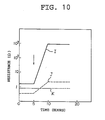
- Fig. 10 shows a change in resistance value as a function of time when the internal fault detection element 40 is exposed to SF6 (atmospheric pressure) including SF4 (concentration: 10 ppm).
- curve I shows the results of measurement of the internal fault detection element 40 in which a thin Ag film 43 having a thickness of 30nm was formed on the substrate 41 and which had on its surface fine projections with a thickness of several ⁇ m to several tens of ⁇ m formed by, for instance, sputtering.
- Curve J shows, by way of comparison, the results of measurement of an internal fault detection element 40 in which a thin Ag film 33 with a thickness of 30 nm was formed on a substrate with a smooth surface by, for instance, sputtering.
- Curve K shows, by way of comparison, the results of measurement of a conventional fault detection element 4 using an Al plate with a thickness of 5 ⁇ m.
- the temperature of each device was maintained at 80°C.
- the symbol ⁇ denotes the time when the SF4 was introduced.
- the sensitivity of the conventional internal fault detection element 4 using the Al plate was very poor, but the internal fault detection element 40 having the thin Ag film 43 formed on the substrate 41 with the fine projections exhibited high-sensitivity response with respect to SF4 , i.e., a decomposed SF6 gas.
- This internal fault detection element 40 exhibited higher sensitivity than that of an internal fault detection device 30 having the thin Ag film 33 on a smooth substrate. This difference is considered to be the respect of the following.
- the thickness of the film will not be uniform, and thickner portions and thinner portions of the thin Ag film 43 will be formed due to the uneven surface of the substrate 41. Consequently, the activity of reaction becomes higher in those thinner portions.
- the difference is also partly due to the large surface area in the case of the substrate 41 having the fine projections. This is supported by the fact that in comparing the specific resistance of the devices using the two different substrates, the specific resistance is greater in the case where the thin Ag film 43 was formed on the substrate 41 having the fine projections.
- an internal fault detection element 40 in which the thin Ag film 43 is formed on the substrate 41 having on its surface the fine projections with a thickness of several ⁇ m to several tens of ⁇ m it is possible to detect at an early period even internal faults in which the concentration of the decomposed SF6 gas is low such as when partial discharges and local heating occur in an electrical apparatus.
- Fig. 11 shows a cross-sectional view schematically illustrating a conventional internal fault detection apparatus as shown in Fig. 2, in which the internal fault detection element 30 or 40 in accordance with the present invention is incorporated.
- the same reference numerals as those of Fig. 2 denote the same or corresponding portions.
- An internal fault detector 61 is provided in such a manner as to be clamped between a gas pipe 21a and side pipe 21b on the gas pipe jointing portion 21.
- reference numeral 17 denotes a flange cover which merely serves to close an opening and is not provided with an internal fault detection portion.
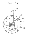
- the internal fault detector 61 is arranged as shown in Fig. 12.
- the internal fault detector 61 comprises a support frame 62 constituted by a planar member having a hollow portion 62a, and the internal fault detection element 30 or 40 fixed to a support crosspiece 62b provided in the hollow portion 62a.
- conductors 54 for outputting a signal output by the internal fault detection element 30 or 40 to the external circuit are hermetically through the support frame 62.
- the gas pipe is removed at the gas pipe jointing portion 21, the internal fault detector 61 is inserted into the gap, and the gas pipe 21a and the side pipe 21b are then joined with the internal fault detector 61 therebetween.
- the SF6 gas 18 inside the hermetic vessel 11 and the thin Ag film 33 or 43 of the internal fault detection element 30 or 40 come into contact with each other.
- the SF6 gas decomposes to form a decomposed SF6 gas.
- This decomposed SF6 gas reacts with the thin Ag film 33 or 43 thereby changing the electrical properties thereof.
- This change in the electrical properties is detected by electrodes 32, the detected signal representing the change is sent to the external circuit (not shown) via the conductors 54, and then an alarm is issued by a device (not shown).
- the internal fault detector 61 is installed in an insulating gas charged electrical apparatus not originally provided with an internal fault detection apparatus, however, the internal fault detector 61 can, of course, be provided in an electrical apparatus which is to be newly installed. In this case, the installation is carried out at the time of installing the piping.
- the flow of the gas is from an area of the gas that is subject to measurement towards the outside due to temperature rises caused by solar heat or flow of current, if the sensitive surface of the internal fault detection element is disposed to face towards the electrical apparatus, the contact between the decomposed SF6 gas and the sensitive surface thereof becomes even more reliable. Accordingly, an internal fault of the electrical apparatus can be detected even faster and more accurately.
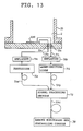
- Fig. 13 is a block diagram of the internal fault detection device in accordance with the present invention, and the same or corresponding portions as those shown in Fig. 5 are denoted by the same reference numerals.
- one end of a conductor 54a is connected to the input side of the internal fault detection element 30 or 40, the other end thereof is connected to a photoelectric conversion secction 71a, such as a photodiode, via an amplifier 70a.
- the other end of this photodiode 71a is connected to a signal processing section 73 by means of an optical fiber 72a.
- one end of another conductor 54b is connected to the output side of the internal fault detection element 30 or 40, and the other end thereof is connected to a photoelectric conversion section 71b, such as a light-emitting diode, via an amplifier 70b.
- the other end of the light-emitting diode 71b is connected to the signal processing section 73 by means of an optical fiber 72b.
- This signal processing section 73 is further connected to a remote monitoring and control console 74 by means of an optical fiber 72c.
- the photodiode 71a and the optical fiber 72a constitute current supplying means.
- Fig. 14 is another block diagram of the internal fault detection device in accordance with the present invention, in which a constant-current generator 75 is used instead of the amplifiers and the photoelectric conversion section 71a as shown in Fig. 13.
- Fig. 15 is a graph illustrating the relationship between the amount of incident light and output current according to an example in which the photodiode 71a is used in the internal fault detection devices as shown in Figs. 13 and 14.
- Fig. 16 “L” and “M” depict direct current and pulse, respectively.
- Fig. 16 is a graph illustrating the relationship between forward current and the output of light according to an example in which the light-emitting diode 71b is used in the internal fault detection devices as shown in Figs. 13 and 14.
- an optical signal sent from the signal processing section 73 as shown in Fig. 13 is led to the photodiode 71a via the optical fiber 72a, where the optical signal is converted into an electrical signal and is then amplified by the amplifier 70a to 1 mA or thereabout. If, for example, light of 6 ⁇ 10 ⁇ 5W is made incident upon the photodiode 71a, an output current of 10 ⁇ 6A is obtained, as is apparent from Fig. 15. This output current is then amplified by the amplifier 70a to 1 mA. The 1 mA current thus obtained is led to the internal fault detection element 30 or 40 via the conductor 54a.
- the SF6 is decomposed and an active decomposed SF6 gas such SF4 and the like is produced.
- This decomposed SF6 gas reacts with the trace amount of water existing in the SF6 and produces HF and the like.
- the gas including HF converts a good conductor Ag of the thin Ag film 33 or 43 of the internal fault detection element 30 or 40 into a bad conductor AgF, in the manner as described above.
- This changes of the electrical signal is amplified by the amplifier 70b, the amplified electrical signal is converted into an optical signal by the light-emitting diode 71b and is then detected.
- the value of resistance which is normally 1,5 ⁇ , is changed to 10 ⁇ when a fault occurs.
- this current is amplified 50 times by the amplifier 70b, the current which would otherwise be 50 mA is changed to 7,5 mA.
- This change in the current is subjected to photoelectric conversion by the light-emitting diode 71b on the basis of the relationship shown in Fig. 16, and its optical output changes from 6,5 mW to 1 mW.
- the optical signal thus obtained is led to the signal processing section 73 through the optical fiber 72b, where the optical signal undergoes signal processing. Furthermore, if the optical signal is sent to the remote monitoring control console 74 by using the optical fiber 72c, an internal fault occcurring in an electrical apparatus can be remotely monitored.
- a current generated by the generator 75 which produces a constant current of, for instance, 1 mA is supplied to the internal fault detection element 30 or 40.
- the subsequent change in the signal takes place in the same manner as the process as shown in Fig. 13.
Landscapes
- Life Sciences & Earth Sciences (AREA)
- Chemical & Material Sciences (AREA)
- General Health & Medical Sciences (AREA)
- General Physics & Mathematics (AREA)
- Health & Medical Sciences (AREA)
- Pathology (AREA)
- Analytical Chemistry (AREA)
- Biochemistry (AREA)
- Immunology (AREA)
- Physics & Mathematics (AREA)
- Chemical Kinetics & Catalysis (AREA)
- Electrochemistry (AREA)
- Biodiversity & Conservation Biology (AREA)
- Ecology (AREA)
- Environmental & Geological Engineering (AREA)
- Environmental Sciences (AREA)
- Investigating Or Analyzing Materials By The Use Of Electric Means (AREA)
- Testing Relating To Insulation (AREA)
Applications Claiming Priority (8)
| Application Number | Priority Date | Filing Date | Title |
|---|---|---|---|
| JP12842/87U | 1987-02-02 | ||
| JP1284287U JPS63121413U (fr) | 1987-02-02 | 1987-02-02 | |
| JP93286/87 | 1987-04-17 | ||
| JP62093286A JPS63262024A (ja) | 1987-04-17 | 1987-04-17 | Sf↓6ガス封入電気機器用内部異常診断素子 |
| JP160838/87 | 1987-06-30 | ||
| JP62160838A JPS648823A (en) | 1987-06-30 | 1987-06-30 | Internal abnormal state diagnosing device for sf6-filled electric apparatus |
| JP62165408A JPS6412807A (en) | 1987-07-03 | 1987-07-03 | Internal abnormality diagnostic element for sf6 gas filled electric device |
| JP165408/87 | 1987-07-03 |
Publications (2)
| Publication Number | Publication Date |
|---|---|
| EP0277623A2 true EP0277623A2 (fr) | 1988-08-10 |
| EP0277623A3 EP0277623A3 (fr) | 1990-01-17 |
Family
ID=27455880
Family Applications (1)
| Application Number | Title | Priority Date | Filing Date |
|---|---|---|---|
| EP88101413A Withdrawn EP0277623A3 (fr) | 1987-02-02 | 1988-02-01 | Elément et appareil pour la détection de défauts internes dans un appareil électrique à isolement gazeux |
Country Status (4)
| Country | Link |
|---|---|
| US (1) | US4839767A (fr) |
| EP (1) | EP0277623A3 (fr) |
| CN (1) | CN1009957B (fr) |
| CA (1) | CA1286361C (fr) |
Cited By (2)
| Publication number | Priority date | Publication date | Assignee | Title |
|---|---|---|---|---|
| US6411110B1 (en) * | 1999-08-17 | 2002-06-25 | Micron Technology, Inc. | Apparatuses and methods for determining if protective coatings on semiconductor substrate holding devices have been compromised |
| US10928435B2 (en) | 2019-07-15 | 2021-02-23 | The Boeing Company | Electrical fault detector and method of use |
Families Citing this family (10)
| Publication number | Priority date | Publication date | Assignee | Title |
|---|---|---|---|---|
| FR2642913B1 (fr) * | 1989-02-07 | 1991-04-12 | Alsthom Gec | Dispositif de securite pour appareil electrique a gaz dielectrique, notamment pour disjoncteurs ou reducteurs de mesure |
| US5466605A (en) * | 1993-03-15 | 1995-11-14 | Arizona Board Of Regents | Method for detection of chemical components |
| DE4331992A1 (de) * | 1993-09-21 | 1995-03-23 | Kloeckner Moeller Gmbh | Gegen Störlichtbögen gesicherte zellenartige Schaltanlage zur Verteilung elektrischer Energie |
| US5985673A (en) * | 1994-12-22 | 1999-11-16 | Arizona Baord Of Regents | Method for regeneration of a sensor |
| US5880354A (en) * | 1997-06-11 | 1999-03-09 | Cts Corporation | Gas sensor with orientation insensitivity |
| CN101059485B (zh) * | 2007-05-23 | 2010-07-21 | 重庆大学 | 六氟化硫放电分解气体组分分析系统及其使用方法 |
| CN101968459B (zh) * | 2010-08-23 | 2013-06-19 | 上海市电力公司 | 一种开关柜内部故障的探测方法 |
| CN102305869B (zh) * | 2011-08-12 | 2013-04-10 | 安徽省电力科学研究院 | 用于电气设备中六氟化硫气体质量分析的仪器 |
| CN105067979A (zh) * | 2015-08-10 | 2015-11-18 | 厦门加华电力科技有限公司 | Sf6电气设备局放分解物综合检测仪及其控制方法 |
| KR101854533B1 (ko) * | 2016-10-28 | 2018-05-03 | 아주대학교산학협력단 | 불소계 가스 감지 장치 및 이의 제조방법 |
Family Cites Families (24)
| Publication number | Priority date | Publication date | Assignee | Title |
|---|---|---|---|---|
| US3648110A (en) * | 1970-08-20 | 1972-03-07 | Bell Telephone Labor Inc | Circuit protection apparatus utilizing optical transmission path |
| CA989005A (en) * | 1971-12-22 | 1976-05-11 | David L. Braun | Mercury detection device |
| US4092119A (en) * | 1973-11-23 | 1978-05-30 | Calspan Corporation | Environmental quality indicator |
| US3970431A (en) * | 1974-01-23 | 1976-07-20 | Stanford Research Institute | Carbon monoxide gas detector |
| US4046512A (en) * | 1976-02-20 | 1977-09-06 | Westinghouse Electric Corporation | Device for indicating overheating in generators |
| JPS5346092A (en) * | 1976-10-08 | 1978-04-25 | Toshiba Corp | Gas leakage alarm device |
| JPS5395097A (en) * | 1977-01-31 | 1978-08-19 | Toshiba Corp | Gas-sensitive element |
| DE2808033A1 (de) * | 1978-02-24 | 1979-08-30 | Siemens Ag | Einrichtung zur unterdrueckung der wasserdampf-querempfindlichkeit bei einem nicht dispersiven infrarot-gasanalysator |
| JPS5749325A (en) * | 1980-09-06 | 1982-03-23 | Hitachi Ltd | Local overheat diagnozing device for rotary electric machine |
| JPS5766347A (en) * | 1980-10-09 | 1982-04-22 | Hitachi Ltd | Detector for mixture gas |
| US4324761A (en) * | 1981-04-01 | 1982-04-13 | General Electric Company | Hydrogen detector |
| US4394635A (en) * | 1981-04-16 | 1983-07-19 | General Electric Company | Method for determining dissolved gas concentrations in dielectric coolants |
| JPS58191962A (ja) * | 1982-05-07 | 1983-11-09 | Hitachi Ltd | ガス検出素子 |
| US4534099A (en) * | 1982-10-15 | 1985-08-13 | Standard Oil Company (Indiana) | Method of making multilayer photoelectrodes and photovoltaic cells |
| US4509034A (en) * | 1983-03-22 | 1985-04-02 | New Cosmos Electric Col, Ltd. | Gas sensor |
| US4505146A (en) * | 1983-06-16 | 1985-03-19 | Allied Corporation | Portable SF6 decomposition sensor |
| JPS6039536A (ja) * | 1983-08-12 | 1985-03-01 | Hochiki Corp | ガスセンサ |
| US4555930A (en) * | 1984-02-14 | 1985-12-03 | Control Instruments Corp. | Digital gas sensing system |
| DE3433362A1 (de) * | 1984-09-07 | 1986-03-20 | Siemens Ag | Metallgekapselte, druckgasisolierte hochspannungsschaltanlage mit mehreren, mittels schottdurchfuehrungsisolatoren gasdicht geschotteten teilabschnitten der kapselung |
| GB8426964D0 (en) * | 1984-10-25 | 1984-11-28 | Sieger Ltd | Adjusting circuit parameter |
| JPS61231828A (ja) * | 1985-04-04 | 1986-10-16 | 三菱電機株式会社 | ガス絶縁開閉装置 |
| JPS626181A (ja) * | 1985-07-02 | 1987-01-13 | Mitsubishi Electric Corp | ガス絶縁機器の異常検出装置 |
| JPH0517650Y2 (fr) * | 1986-01-31 | 1993-05-12 | ||
| US4685325A (en) * | 1986-02-03 | 1987-08-11 | Aluminum Company Of America | Measurement of gas content in molten metal using a constant current source |
-
1988
- 1988-01-27 US US07/149,168 patent/US4839767A/en not_active Expired - Fee Related
- 1988-01-29 CA CA000557745A patent/CA1286361C/fr not_active Expired - Lifetime
- 1988-02-01 CN CN88100511.8A patent/CN1009957B/zh not_active Expired
- 1988-02-01 EP EP88101413A patent/EP0277623A3/fr not_active Withdrawn
Cited By (2)
| Publication number | Priority date | Publication date | Assignee | Title |
|---|---|---|---|---|
| US6411110B1 (en) * | 1999-08-17 | 2002-06-25 | Micron Technology, Inc. | Apparatuses and methods for determining if protective coatings on semiconductor substrate holding devices have been compromised |
| US10928435B2 (en) | 2019-07-15 | 2021-02-23 | The Boeing Company | Electrical fault detector and method of use |
Also Published As
| Publication number | Publication date |
|---|---|
| CN88100511A (zh) | 1988-08-31 |
| CN1009957B (zh) | 1990-10-10 |
| US4839767A (en) | 1989-06-13 |
| EP0277623A3 (fr) | 1990-01-17 |
| CA1286361C (fr) | 1991-07-16 |
Similar Documents
| Publication | Publication Date | Title |
|---|---|---|
| US4839767A (en) | Element and device for detecting internal faults in an insulating gas charged electrical apparatus | |
| US4510441A (en) | Electric field detector | |
| GB2142147A (en) | Gas sensor | |
| Jones et al. | Optical fibre based sensing using chromatic modulation | |
| KR100806876B1 (ko) | 가연성 가스 누설 감지기용 접촉연소식 가스센서 | |
| JP3029269B2 (ja) | 絶縁物異常検出装置 | |
| KR910000084B1 (ko) | Sf_6 가스봉입 전기기기용 내부 이상 진단장치 | |
| EP0366098A2 (fr) | Détecteur de gaz | |
| CN110426315A (zh) | 一种机电一体化的气体密度继电器及系统 | |
| EP0441659A1 (fr) | Détection d'une fissure dans la paroi d'un capteur électrochimique | |
| JPH07509567A (ja) | 薄膜ガスセンサーとその製造方法 | |
| JPS58224516A (ja) | 異常監視装置 | |
| CN115616361A (zh) | 一种基于光纤传感的全密封开关柜监测系统及方法 | |
| RU2609223C1 (ru) | Тензорезисторный датчик абсолютного давления на основе кни микроэлектромеханической системы | |
| CN211179415U (zh) | 一种机电一体化的气体密度继电器及系统 | |
| JPS61285013A (ja) | Sf↓6分解ガス検知装置 | |
| JPS648823A (en) | Internal abnormal state diagnosing device for sf6-filled electric apparatus | |
| US5333159A (en) | Radiation gauge | |
| JPH07318447A (ja) | 真空度監視装置 | |
| TWI743985B (zh) | 氣體感測器製造方法 | |
| JPH01278223A (ja) | Sf↓6ガス封入電気機器用内部異常診断装置 | |
| JPS62211531A (ja) | 真空計装置 | |
| JPH0566215A (ja) | ガスセンサ | |
| JPH0644029B2 (ja) | ガス絶縁電気機器の異常検知装置 | |
| JPS57153229A (en) | Detecting device for abnormal temperature of gas insulating apparatus |
Legal Events
| Date | Code | Title | Description |
|---|---|---|---|
| PUAI | Public reference made under article 153(3) epc to a published international application that has entered the european phase |
Free format text: ORIGINAL CODE: 0009012 |
|
| AK | Designated contracting states |
Kind code of ref document: A2 Designated state(s): CH DE FR LI |
|
| PUAL | Search report despatched |
Free format text: ORIGINAL CODE: 0009013 |
|
| RHK1 | Main classification (correction) |
Ipc: G01N 27/12 |
|
| AK | Designated contracting states |
Kind code of ref document: A3 Designated state(s): CH DE FR LI |
|
| 17P | Request for examination filed |
Effective date: 19900109 |
|
| 17Q | First examination report despatched |
Effective date: 19910327 |
|
| STAA | Information on the status of an ep patent application or granted ep patent |
Free format text: STATUS: THE APPLICATION IS DEEMED TO BE WITHDRAWN |
|
| 18D | Application deemed to be withdrawn |
Effective date: 19930929 |