EP0277629A2 - Procédé et dispositif pour la détection d'impuretés dans des fluides - Google Patents
Procédé et dispositif pour la détection d'impuretés dans des fluides Download PDFInfo
- Publication number
- EP0277629A2 EP0277629A2 EP88101443A EP88101443A EP0277629A2 EP 0277629 A2 EP0277629 A2 EP 0277629A2 EP 88101443 A EP88101443 A EP 88101443A EP 88101443 A EP88101443 A EP 88101443A EP 0277629 A2 EP0277629 A2 EP 0277629A2
- Authority
- EP
- European Patent Office
- Prior art keywords
- fluid
- light
- intensity
- measurement
- bottles
- Prior art date
- Legal status (The legal status is an assumption and is not a legal conclusion. Google has not performed a legal analysis and makes no representation as to the accuracy of the status listed.)
- Granted
Links
Images


Classifications
-
- G—PHYSICS
- G01—MEASURING; TESTING
- G01N—INVESTIGATING OR ANALYSING MATERIALS BY DETERMINING THEIR CHEMICAL OR PHYSICAL PROPERTIES
- G01N21/00—Investigating or analysing materials by the use of optical means, i.e. using sub-millimetre waves, infrared, visible or ultraviolet light
- G01N21/84—Systems specially adapted for particular applications
- G01N21/88—Investigating the presence of flaws or contamination
- G01N21/90—Investigating the presence of flaws or contamination in a container or its contents
- G01N21/9018—Dirt detection in containers
- G01N21/9027—Dirt detection in containers in containers after filling
-
- G—PHYSICS
- G01—MEASURING; TESTING
- G01N—INVESTIGATING OR ANALYSING MATERIALS BY DETERMINING THEIR CHEMICAL OR PHYSICAL PROPERTIES
- G01N33/00—Investigating or analysing materials by specific methods not covered by groups G01N1/00 - G01N31/00
- G01N33/0078—Testing material properties on manufactured objects
- G01N33/0081—Containers; Packages; Bottles
-
- G—PHYSICS
- G01—MEASURING; TESTING
- G01N—INVESTIGATING OR ANALYSING MATERIALS BY DETERMINING THEIR CHEMICAL OR PHYSICAL PROPERTIES
- G01N21/00—Investigating or analysing materials by the use of optical means, i.e. using sub-millimetre waves, infrared, visible or ultraviolet light
- G01N21/17—Systems in which incident light is modified in accordance with the properties of the material investigated
- G01N21/21—Polarisation-affecting properties
Definitions
- the invention relates to a method for the detection of foreign bodies in fluids, in particular liquids contained in bottles, such as infusion solutions or the like, wherein the fluid is illuminated over a large area with polarized light and the light passing through the fluid is viewed by a crossed analyzer, thereby causing the Fluid falling light is largely darkened.
- infusion liquids in particular in infusion bottles, which hold an amount of at least one hundred milliliters, but usually several hundred milliliters and typically one liter
- foreign particles such as, for example, rubber or cork particles of the closure
- Metal particles, threads or the like From a certain size, such as fifty micrometers or more, such foreign particles pose the risk of clogging the cavity of an infusion needle.
- a hazard can continue of the patient occur when such relatively large particles enter the bloodstream. It is therefore necessary to examine such infusion bottles for larger foreign particles so that infusion bottles with large foreign particles can be sorted out, while bottles with smaller particles can remain.
- DE-OS 31 45 668 proposes a device for optically examining liquid vessel contents for foreign bodies with a laser, the beam of which is directed onto a cylindrical mirror surface, reflected by it and expanded in one plane (also a light curtain), which illuminates the liquid in a linear manner, with a series of light-sensitive detectors arranged behind the liquid in the plane spanned by the light curtain is.
- a particle that gets into the expanded laser beam darkens it, which is to be determined by the photo elements as a deviation from normal lighting.
- This known device did not provide satisfactory results, for example because the measurement result was not dependent on particle size and the laser intensity falling up and down in accordance with a Gaussian distribution did not allow the required detection reliability in these areas.
- the invention is based on the object of a method and a device for the objective detection of foreign bodies in fluids, in particular over larger observation areas of more than 20 qcm, preferably of more than To create 50 qcm, which enables reliable discrimination of the particles by their size.
- the above-mentioned object is achieved by a method which is characterized in that the fluid is viewed on the near the optical axis of the light incident on the fluid and the light intensity of individual measuring zones is determined by optoelectric conversion, that the measured intensity in each case with an adjustable Value is compared and that if the value is exceeded during a measurement interval, corresponding signals are generated.
- a device according to the invention provides that the light source, possibly by additional optical elements, illuminates the fluid areally, since a polarizer is arranged in front of the fluid, an analyzer is arranged behind the fluid, and that the light source is essentially diametrically directed across the fluid opposite, a television camera is arranged as a detection device.
- the invention takes up the observation in the dark field of the old subjective method. Since the particles in the liquid do not shine and do not continue to shine, a possibility had to be created to make the background image taken by the camera as dark as possible, but to achieve a selective brightening in the presence of particles. This is achieved by two - possibly taking into account the optical activity of the liquid itself - crossed polarizers, which are thus set in such a way that their polarization directions (in the case of non-optical liquid) are perpendicular to one another, and thus the background is largely darkened.
- the foreign particles in liquids not only scatter the light, but also lift it Surprisingly, the polarization of the light carried out by the first polarizer largely also results in depolarization, so that the television camera can detect an intense light spot due to the light scattered on the particle.
- the greatest scattering brightness and the best monotonous dependence of the scattered light intensity on the particle size was obtained for the particles of interest here (larger) in the forward scattering direction, so that optical locations of the light source, scattering cell and camera should therefore preferably be aligned.
- the scatter cell i.e. a bottle to be examined, should therefore be viewed against the light on the optical axis of the incident light.
- a preferred embodiment provides that the region of the optical axis of the light beam is masked out or that in the case of one Fluid covering convex lateral surface is provided centrally in front of this, a cover extending between the same and the light source or the camera extending parallel to the axis of the lateral surface.
- incoherent light This can be white or colored light, possibly through Be color filtering. In the latter case, it is largely impossible to influence the detection by extraneous light, such as daylight.
- a light-tight encapsulation of the system can then be omitted - compared to the use of white light from an incandescent lamp.
- a color filter could be placed in front of the camera lens.
- the resolution of the camera should be in the range of the size of the particles of interest (typically DE-OS 30 43 031). This meant that on the one hand only a small cross-sectional area - and thus only ampoules - but not larger bottles could be examined, on the other hand the scope of evaluation was considerable and required large computers and a large amount of time.
- another extremely preferred embodiment provides that the intensity of a plurality of scanning pixels is combined to form a measuring zone, that is to say is added as an average.
- a measuring zone preferably has the order of 30 ⁇ 30 individual scanning points of a conventional television camera. This simplifies the further processing of the measured intensity without fear of loss of information.
- This preferred embodiment enables real-time processing with an inexpensive computer such as, in particular, a standard desktop computer as a personal computer.
- the free surface of the fluid is hidden from the light beam or that a cover is arranged in front of the surface of the fluid.
- edge areas of the fluid are masked out or that a mask covering their edge area is covered in front of the illuminated area of the fluid is arranged.
- the masking out of certain edge areas by masks or diaphragms is not critical insofar as they are actually comparatively small in terms of their area, since the foreign particles move in the fluids and the measuring time can in each case be selected such that a moving foreign particle to be detected is in any case is detected.
- a measuring time of 1 second is quite sufficient here. This applies in particular when the fluid is set in motion, preferably in rotation, this being possible in particular in that a turntable is provided in order to set the liquid in motion.
- a further development provides that the fluid is set in motion at a controlled increasing speed or that the turntable can be set in motion by means of a control device such that its speed changes continuously and continuously.
- the measuring device is separated and decoupled from other devices such as the conveyors, in particular they do not have any common frames, frames or the like. have, but are only connected via the common stand.
- the bottles to be examined are transferred for measurement by a conveyor holding elements of the measuring device and then released by the conveyor, so that they are also no longer connected.
- the conveyor can be a paternoster, which grips the bottle preferably at the neck under the closure by means of a fork.
- the bottles can be placed on a shelf in the measuring cell, but are preferably gripped by two beakers which can simultaneously form vertical edge shutters. In any case, the paternoster fork detaches from the bottle head and then releases it to the measuring cell so that the measurement can be carried out.
- the device 1 has a light source 2 in the form of a light bulb. This can be followed by a lens system 3 for expanding and parallelizing the light. Deflecting mirror 3 ⁇ ensure a compact design of the device.
- a fluid in particular a liquid, is passed through or introduced into a measuring cell 4.
- the measuring cell has a turntable 6, on which infusion bottles 7 with an infusion solution 8 are placed, set in rotation and then stopped again, whereupon the measurement is carried out with a rotating liquid.
- the bottles can also be rotated on a rotation device which is spatially separate from the measuring cell, thus causing the liquid 8 in the bottle 7 to rotate and then the bottles being introduced into the measuring cell 4.
- the bottles 7 can be held for measurement by interchangeable adapters 5 on the bottle neck or by clamping basins 10 on the main part (FIG. 2), the clamping basins 10 forming side panels 10a. Together with - also interchangeable masks 9 - described in detail below, an adaptation to different bottles can be carried out. Furthermore, a liquid flow could be led through the measuring cell, for example in a tube or a channel, which has transparent windows on the side facing the light source 2 and on the side facing away from it.
- a mask 9 is arranged in front of the measuring cell 4, which is only shown in perspective for illustration, but is actually perpendicular to the beam direction or to the light source-camera connecting line, which masks part of the light beam or covers part of the bottle 8 .
- the bottom area 12 of the bottle can also be covered.
- cylindrical bottles as is shown in FIG.
- the mask 9 is divided into two windows 13, which are separated from one another by a central cover strip 14.
- a first polarizer 16 - On both sides of the measuring cell perpendicular to the direction of the light beam in front of the measuring cell there is a first polarizer 16 - to which the mask 9 can be applied - and a further polarizer or analyzer 17 is arranged behind the measuring cell.
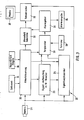
- the image evaluation unit has an output 24, via which it emits a signal, in particular a control signal for a selection switch for sorting out defective bottles.
- a sequence control 26 is provided which controls the image evaluation unit 22 on the one hand via a drive control 27 27, a motor 27 of the turntable 6 and on the other hand.
- the image evaluation unit 22 has a signal conditioner 23 with an analog-digital converter.
- the recorded signal of the individual measurement signal from the camera is measured over a larger measurement zone of, for example, 30 ⁇ 30 measurement pixels summed or averaged and processed as such a sum signal.
- the signal conditioner 23 is followed on the one hand by a main signal memory 25 and on the other hand by a comparator 29 which also has an input for an output of the main signal memory 25. Furthermore, a tolerance sensor or threshold value set 28 is assigned to the comparator.
- the comparator is followed by an alarm transmitter 31, on the one hand an alarm output unit 24, by which the switches in the conveying path of the bottles are controlled by a control signal, is controlled.
- the signal from the camera 21 is also passed to a video mixer 32, which on the other hand is also supplied with a signal from the alarm generator 31 via an alarm field generator 33.
- the sequence control unit 26 can specify the cycle time via an input 34 and the desired measuring interval via an input 36 (FIG. 2).
- the measuring cell 4 is illuminated with light 5 by the light source 2.
- the polarizers 16, 17 are set in relation to one another such that the intensity of the light passing through the analyzer 17 and falling on the camera 21 is minimal, possibly taking into account an optically active liquid 8 in the bottle 7.
- the bottle 8 is set in rotation by a sequence control for a predetermined time by means of a motor, the rotation preferably taking place at a controlled increasing and later continuously decreasing speed so that jerky movements and vibrations are avoided.
- particles which have settled on the bottom 12 of the bottle are whirled on and through the liquid so that they are detected in their movement.
- a certain waiting time to calm the liquid movement which continues to rotate even after the rotary plate 6 and the bottle 8 have come to a standstill, measurements are taken over a predetermined measurement interval, ie the image evaluation unit 22 is activated.
- the signal from the camera 21 is first fed to the monitor 30 via the video mixer 32, so that the image of the bottle 8 under test can be permanently observed there.
- the recorded image signal from the camera 21 is fed to the signal conditioner 23 and digitized therein.
- the digital signal is fed to the signal main memory 25 and stored there. Furthermore, the digital signal is repeated several times, e.g. every 50 m / s to the comparator 29, to which the sequence control unit 26 also feeds the image stored in the signal main memory 25.
- the comparator 29 records the differences at different times, compares corresponding image sections (measuring zones) and determines whether the differences are above or below an externally entered tolerance or threshold value. This threshold corresponds to a certain difference in brightness and is therefore a measure of the particle size (assuming at least the same type of particle).
- an alarm signal is emitted, possibly in the form of a control signal for a switch which determines the further conveying path of the bottles, so that the bottle which has moved the signal can be eliminated.
- the signal is fed to an alarm field generator 33 which displays a marker on the monitor 30 in the measurement zone or image section in question via the video mixer 32, thereby indicating where a foreign particle has been found.
- the image evaluation unit therefore compares in a comparator the brightness of the individual zones of the image recorded by the camera 21 or their deviation, which is determined by means of a differential amplifier, in the comparator 29 with a threshold value of a threshold value generator 28 which is predetermined in accordance with the desired tolerance. If the threshold value is exceeded, the image evaluation unit 22 inputs Signal via an alarm output 24.
- This can be an acoustic or optical signal that indicates that the bottle that has just been checked is not in order and should therefore be discarded.
- Automatically supplied and continued bottles can be a control signal that actuates a switch through which the defective bottle that has just been checked is branched off from the conveying path of the bottles found to be in order.
- a threshold value is set in such a way that particles which are, for example, larger than 50 micrometers (taking tolerances into account) lead to a control signal via the control line 24, but smaller particles do not.
- the limit for infusion solutions is set so low that infusion bottles which are found to be good do not contain any particles which lead to blockage of the infusion needle or a hazard of the patient with regard to thrombosis, which should be avoided, but on the other hand the size should not be set so low that an excessive number of bottles would be excreted, although at best these contain particles that are not critical. It has been shown that the device according to the invention enables selection with sufficient accuracy.
- the increased intensity is increased not only in a raster point or only in a size of the particle corresponding area of the recording tube scanned by the electron beam, but in a larger area of a plurality of raster points of a conventional one Television camera.
- a camera with CCDs but a vidicon, in particular a Z-Vidicon or Novicon, is preferred above all for larger bottles, since it enables a sensitivity which is many times higher than that of a CCD camera.
- the individual halftone dots of the television camera are combined to form larger evaluation areas which, for example, have 30 ⁇ 30 halftone dots and within which the intensities of the individual halftone dots are averaged and an average overall intensity is determined and processed becomes. This contributes to simplifying further processing and reducing the processing effort.
Landscapes
- Chemical & Material Sciences (AREA)
- Health & Medical Sciences (AREA)
- Life Sciences & Earth Sciences (AREA)
- General Health & Medical Sciences (AREA)
- Analytical Chemistry (AREA)
- Biochemistry (AREA)
- Physics & Mathematics (AREA)
- General Physics & Mathematics (AREA)
- Immunology (AREA)
- Pathology (AREA)
- Engineering & Computer Science (AREA)
- Food Science & Technology (AREA)
- Medicinal Chemistry (AREA)
- Investigating Materials By The Use Of Optical Means Adapted For Particular Applications (AREA)
- Investigating Or Analysing Materials By Optical Means (AREA)
Applications Claiming Priority (2)
| Application Number | Priority Date | Filing Date | Title |
|---|---|---|---|
| DE3703306 | 1987-02-04 | ||
| DE3703306 | 1987-02-04 |
Publications (3)
| Publication Number | Publication Date |
|---|---|
| EP0277629A2 true EP0277629A2 (fr) | 1988-08-10 |
| EP0277629A3 EP0277629A3 (en) | 1989-10-11 |
| EP0277629B1 EP0277629B1 (fr) | 1993-05-05 |
Family
ID=6320187
Family Applications (1)
| Application Number | Title | Priority Date | Filing Date |
|---|---|---|---|
| EP88101443A Expired - Lifetime EP0277629B1 (fr) | 1987-02-04 | 1988-02-02 | Procédé et dispositif pour la détection d'impuretés dans des fluides |
Country Status (3)
| Country | Link |
|---|---|
| US (1) | US4902137A (fr) |
| EP (1) | EP0277629B1 (fr) |
| DE (1) | DE3880700D1 (fr) |
Cited By (5)
| Publication number | Priority date | Publication date | Assignee | Title |
|---|---|---|---|---|
| EP0401484A1 (fr) * | 1989-04-06 | 1990-12-12 | Harro Höfliger Verpackungsmaschinen GmbH | Procédé pour maintenir sans poussière un appareil de détection de particules étrangères dans des fluides |
| FR2726651A1 (fr) * | 1994-11-08 | 1996-05-10 | Bertin & Cie | Procede et dispositif de detection de corps etrangers dans des recipients transparents tels que des bouteilles |
| EP2383567A1 (fr) * | 2010-04-29 | 2011-11-02 | Krones AG | Reconnaissance de matière en suspension dans des récipients remplis de liquide |
| US8405826B2 (en) | 2006-11-15 | 2013-03-26 | Khs Gmbh | Method for the inspection of bottles or containers in a bottling or container filling plant and an apparatus for the inspection of bottles or containers |
| EP2639573A3 (fr) * | 2012-03-16 | 2013-11-06 | Krones AG | Dispositif d'utilisation pour une inspection de récipient, système d'inspection et procédé d'inspection |
Families Citing this family (33)
| Publication number | Priority date | Publication date | Assignee | Title |
|---|---|---|---|---|
| US5144124A (en) * | 1990-11-19 | 1992-09-01 | Emhart Industries, Inc. | Glass container inspection machine with plot display of container and light intensity |
| FR2681133A1 (fr) * | 1991-09-11 | 1993-03-12 | Languedoc Verrerie | Dispositif d'emission ou d'absorption de lumiere pour le controle sans contact d'objets. |
| DE4205722C2 (de) * | 1992-02-25 | 1994-07-14 | Krieg Gunther | Verfahren und Vorrichtung zur Identifikation und Unterscheidung zwischen Schadstoffen und Inhaltsstoffen in Behältern |
| US5444535A (en) * | 1993-08-09 | 1995-08-22 | Labatt Brewing Company Limited | High signal-to-noise optical apparatus and method for glass bottle thread damage detection |
| US6067155A (en) * | 1997-12-24 | 2000-05-23 | Owens-Brockway Glass Container Inc. | Optical inspection of transparent containers using infrared and polarized visible light |
| US6011620A (en) * | 1998-04-06 | 2000-01-04 | Northrop Grumman Corporation | Method and apparatus for the automatic inspection of optically transmissive planar objects |
| US6408679B1 (en) * | 2000-02-04 | 2002-06-25 | The United States Of America As Represented By The Administrator Of The National Aeronautics And Space Administration | Bubble measuring instrument and method |
| US6765675B2 (en) * | 2000-02-14 | 2004-07-20 | M. W. Technologies, Inc. | Fluid inspection apparatus with vibrator |
| FI111734B (fi) * | 2001-01-03 | 2003-09-15 | Valtion Teknillinen | Menetelmä nestemuodossa olevan polymeerin tarkkailemiseksi |
| FR2847670B1 (fr) * | 2002-11-26 | 2005-06-10 | Sc2N Sa | Detecteur par voie optique de la presence de bulles de gaz dans un liquide |
| DE10257749B4 (de) * | 2002-12-10 | 2006-05-04 | Krones Ag | Vorrichtung zum Inspizieren von gefüllten und verschlossenen Gefäßen |
| US7728873B2 (en) * | 2004-11-09 | 2010-06-01 | Cnoga Ltd | Apparatus for obtaining and electronically interpreting digital images of liquids, solids and combinations on liquids and solids |
| KR100853196B1 (ko) * | 2007-12-11 | 2008-08-20 | (주)실리콘화일 | 스펙트럼센서를 구비하는 이미지 센서 |
| US8345239B1 (en) * | 2008-08-04 | 2013-01-01 | Fluid Imaging Technologies, Inc. | System and method for monitoring birefringent particles in a fluid |
| DE102009039254A1 (de) * | 2009-08-28 | 2013-05-08 | Krones Aktiengesellschaft | Vorrichtung und Verfahren zum Inspizieren etikettierter Gefäße |
| US7982201B2 (en) * | 2009-09-08 | 2011-07-19 | Jadak, Llc | System and method for detection of liquid level in a vessel |
| PL2458367T3 (pl) * | 2010-11-25 | 2015-12-31 | Mettler Toledo Gmbh | Urządzenie oraz sposób do rozpoznawania substancji stałych w fazie ciekłej |
| US8994945B2 (en) | 2011-10-27 | 2015-03-31 | Fluid Imaging Technologies, Inc. | Method of treatment analysis with particle imaging |
| CN102661955B (zh) * | 2012-04-25 | 2014-08-20 | 北京先驱威锋技术开发公司 | 一种可见异物的检测系统 |
| CN102914547B (zh) * | 2012-10-09 | 2015-04-22 | 上海交通大学 | 自动检测瓶装液体中杂质的系统和方法 |
| DE102013201798A1 (de) * | 2013-02-05 | 2014-08-07 | Krones Ag | Fremdkörperinspektion in gefüllten Behältern |
| DE102013210259B4 (de) | 2013-06-03 | 2022-06-23 | Postnova Analytics Gmbh | Verfahren zur Messung von Streulicht und Vorrichtung zur Messung von Streulicht |
| CN103743676B (zh) * | 2013-07-17 | 2014-11-05 | 张玉武 | 利用点光源隔瓶探测仪 |
| WO2016044427A1 (fr) * | 2014-09-17 | 2016-03-24 | Quest Diagnostics Investments Incorporated | Dispositif et procédé d'évaluation de quantité d'échantillon biologique dans un récipient d'échantillon |
| US9366617B1 (en) * | 2015-07-10 | 2016-06-14 | David E. Doggett | Self-stirring container |
| US9677988B1 (en) | 2015-07-10 | 2017-06-13 | David E. Doggett | Integrating radiation collection and detection apparatus |
| US9983115B2 (en) | 2015-09-21 | 2018-05-29 | Fluid Imaging Technologies, Inc. | System and method for monitoring particles in a fluid using ratiometric cytometry |
| JP6749814B2 (ja) * | 2015-11-12 | 2020-09-02 | Ntn株式会社 | 高さ検出装置およびそれを搭載した塗布装置 |
| EP3376156B1 (fr) | 2015-11-12 | 2022-03-02 | NTN Corporation | Appareil de détection de hauteur et appareil d'application de revêtement équipé d'un tel appareil |
| GB201601960D0 (en) * | 2016-02-03 | 2016-03-16 | Glaxosmithkline Biolog Sa | Novel device |
| JP7046819B2 (ja) * | 2016-02-24 | 2022-04-04 | ベクトン ディキンソン フランス | 透明シリンダを検査するためのシステムおよび方法 |
| US10921235B2 (en) * | 2018-09-17 | 2021-02-16 | Honeywell International Inc. | Foul-resistant coating of windows for optical particle sensing |
| CN110261322B (zh) * | 2019-06-21 | 2023-03-14 | 山东明佳科技有限公司 | 一种瓶装透明溶液微小杂质检测光学成像系统和方法 |
Family Cites Families (13)
| Publication number | Priority date | Publication date | Assignee | Title |
|---|---|---|---|---|
| FR1436128A (fr) * | 1964-03-27 | 1966-04-22 | Egyesuelt Izzolampa | Instrument et procédé pour déterminer les impuretés dans des liquides mobiles et en particulier le contenu d'ampoules avec dispositif d'éjection automatique des ampoules |
| DE1573687C3 (de) * | 1965-03-12 | 1974-07-25 | Dr. Madaus & Co, 5000 Koeln | Verfahren zum Prüfen gefüllter Ampullen auf ihre und ihres Inhalts einwandfreie Beschaffenheit und Vorrichtung zu seiner Durchführung |
| US3598907A (en) * | 1968-05-20 | 1971-08-10 | Emhart Corp | Article inspection by successively televised images |
| HU163859B (fr) * | 1971-09-22 | 1973-11-28 | ||
| US3963348A (en) * | 1972-07-14 | 1976-06-15 | Yamamura Glass Kabushiki Kaisha | Device for detecting strain and foreign matters in glass container by a non-storage type pickup tube |
| IT1048490B (it) * | 1974-09-12 | 1980-11-20 | Scherico Ltd | Metodo ed apparecchio per controllare liquidi entro contenitori trasparenti |
| US4050824A (en) * | 1974-12-19 | 1977-09-27 | Tsn Company, Inc. | Method and apparatus for inspecting bottled goods |
| US4274745A (en) * | 1977-05-12 | 1981-06-23 | Eisai Co., Ltd. | Method and apparatus for detecting foreign matters in liquids |
| JPS5546172A (en) * | 1978-09-29 | 1980-03-31 | Kirin Brewery Co Ltd | Detector for foreign material |
| DE3043031A1 (de) * | 1980-11-14 | 1982-06-03 | Leningradskoe naučno-proizvodstvennoe ob"edinenie technologičeskogo oborudovanija dlja proizvodstva gotovych lekarstvennych sredstv Progress, Leningrad | Einrichtung zum nachweis von fremdpartikeln in einer fluessigkeit |
| DE3145686C2 (de) * | 1981-11-19 | 1985-07-25 | Hans P. Friedrich Elektrotechnik GmbH, 7067 Urbach | Vorrichtung zum Untersuchen von Gefäßinhalten |
| FR2520875A1 (fr) * | 1982-02-01 | 1983-08-05 | Aerospatiale | Procede et dispositif de detection de corps etrangers dans un liquide |
| JPS59114445A (ja) * | 1982-12-21 | 1984-07-02 | Yamamura Glass Kk | 透明体の欠陥検出装置 |
-
1988
- 1988-02-02 DE DE8888101443T patent/DE3880700D1/de not_active Expired - Fee Related
- 1988-02-02 EP EP88101443A patent/EP0277629B1/fr not_active Expired - Lifetime
- 1988-02-04 US US07/152,329 patent/US4902137A/en not_active Expired - Fee Related
Cited By (6)
| Publication number | Priority date | Publication date | Assignee | Title |
|---|---|---|---|---|
| EP0401484A1 (fr) * | 1989-04-06 | 1990-12-12 | Harro Höfliger Verpackungsmaschinen GmbH | Procédé pour maintenir sans poussière un appareil de détection de particules étrangères dans des fluides |
| FR2726651A1 (fr) * | 1994-11-08 | 1996-05-10 | Bertin & Cie | Procede et dispositif de detection de corps etrangers dans des recipients transparents tels que des bouteilles |
| US8405826B2 (en) | 2006-11-15 | 2013-03-26 | Khs Gmbh | Method for the inspection of bottles or containers in a bottling or container filling plant and an apparatus for the inspection of bottles or containers |
| EP2383567A1 (fr) * | 2010-04-29 | 2011-11-02 | Krones AG | Reconnaissance de matière en suspension dans des récipients remplis de liquide |
| DE102010018823B4 (de) | 2010-04-29 | 2021-09-23 | Krones Aktiengesellschaft | Schwebstofferkennung in mit Flüssigkeit befüllten Behältnissen |
| EP2639573A3 (fr) * | 2012-03-16 | 2013-11-06 | Krones AG | Dispositif d'utilisation pour une inspection de récipient, système d'inspection et procédé d'inspection |
Also Published As
| Publication number | Publication date |
|---|---|
| EP0277629A3 (en) | 1989-10-11 |
| EP0277629B1 (fr) | 1993-05-05 |
| DE3880700D1 (de) | 1993-06-09 |
| US4902137A (en) | 1990-02-20 |
Similar Documents
| Publication | Publication Date | Title |
|---|---|---|
| EP0277629B1 (fr) | Procédé et dispositif pour la détection d'impuretés dans des fluides | |
| DE2539766A1 (de) | Verfahren und vorrichtung zur pruefung von fluessigkeitsgefuellten transparenten gefaessen auf anwesenheit von fremdstoffteilchen in der fluessigkeit | |
| DE69131844T2 (de) | Bildgebender Durchflusszytometer | |
| DE69317103T3 (de) | Beleuchtungssystem zur Inspektion von Kontaktlinsen | |
| DE2106945C3 (de) | Verfahren und Vorrichtung zur Prüfung von Flüssigkeiten | |
| DE69214770T2 (de) | Bildgebender Durchflusszytometer | |
| DE69124753T2 (de) | Verfahren und Vorrichtung zur Messung interner Fehler | |
| DE69416680T2 (de) | Vorrichtung zur untersuchung von optischen elementen | |
| DE69219501T2 (de) | Verfahren und Vorrichtung zum Nachweis von Teilchen | |
| DE69724711T2 (de) | Verfahren und Vorrichtung zur optischen Kontrolle | |
| DE3119688C2 (fr) | ||
| DE3007233C2 (de) | Verfahren und Einrichtung zur Fehlerbestimmung von Oberflächen | |
| DE60223956T2 (de) | Untersuchungsgerät und System zur Untersuchung von Fremdkörpern in mit Flüssigkeit gefüllten Behältern | |
| DE3041178C2 (fr) | ||
| DE69622588T2 (de) | Fluorometer | |
| DE102012205311B4 (de) | Optische Vorrichtung, insbesondere Polarimeter, zur Detektion von Inhomogenitäten in einer Probe | |
| DE69714401T2 (de) | Optisches Verfahren und Vorrichtung zum Erkennen von Fehlstellen | |
| DE3620129A1 (de) | Vorrichtung zum pruefen von bauteilen aus transparentem material auf oberflaechenfehler und einschluesse | |
| DE69515845T2 (de) | Untersuchung eines diamanten | |
| DE1925693C3 (de) | Verfahren und Vorrichtung zum Ermitteln von Fremdkörpern in einer in einem durchsichtigen Gefäß enthaltenen Flüssigkeit | |
| DE3878213T2 (de) | Verfahren und vorrichtung zum pruefen eines transparenten behaelters. | |
| DE68908094T2 (de) | Teilchenmessvorrichtung. | |
| DE3906281A1 (de) | Verfahren und vorrichtung zum optischen ueberpruefen des aussehens chipartiger bauteile und zum sortieren der chipartigen bauteile | |
| DE2844679A1 (de) | Vorrichtung zum pruefen der seitenwaende von flaschen | |
| DE3926349A1 (de) | Optische fehlerinspektionsvorrichtung |
Legal Events
| Date | Code | Title | Description |
|---|---|---|---|
| PUAI | Public reference made under article 153(3) epc to a published international application that has entered the european phase |
Free format text: ORIGINAL CODE: 0009012 |
|
| AK | Designated contracting states |
Kind code of ref document: A2 Designated state(s): CH DE FR GB IT LI SE |
|
| PUAL | Search report despatched |
Free format text: ORIGINAL CODE: 0009013 |
|
| AK | Designated contracting states |
Kind code of ref document: A3 Designated state(s): CH DE FR GB IT LI SE |
|
| 17P | Request for examination filed |
Effective date: 19900113 |
|
| 17Q | First examination report despatched |
Effective date: 19910419 |
|
| GRAA | (expected) grant |
Free format text: ORIGINAL CODE: 0009210 |
|
| AK | Designated contracting states |
Kind code of ref document: B1 Designated state(s): CH DE FR GB IT LI SE |
|
| ET | Fr: translation filed | ||
| REF | Corresponds to: |
Ref document number: 3880700 Country of ref document: DE Date of ref document: 19930609 |
|
| GBT | Gb: translation of ep patent filed (gb section 77(6)(a)/1977) |
Effective date: 19930526 |
|
| ITF | It: translation for a ep patent filed | ||
| PG25 | Lapsed in a contracting state [announced via postgrant information from national office to epo] |
Ref country code: LI Effective date: 19940228 Ref country code: CH Effective date: 19940228 |
|
| PLBE | No opposition filed within time limit |
Free format text: ORIGINAL CODE: 0009261 |
|
| STAA | Information on the status of an ep patent application or granted ep patent |
Free format text: STATUS: NO OPPOSITION FILED WITHIN TIME LIMIT |
|
| 26N | No opposition filed | ||
| REG | Reference to a national code |
Ref country code: CH Ref legal event code: PL |
|
| EAL | Se: european patent in force in sweden |
Ref document number: 88101443.5 |
|
| PGFP | Annual fee paid to national office [announced via postgrant information from national office to epo] |
Ref country code: FR Payment date: 19960130 Year of fee payment: 9 |
|
| PGFP | Annual fee paid to national office [announced via postgrant information from national office to epo] |
Ref country code: GB Payment date: 19960131 Year of fee payment: 9 |
|
| PGFP | Annual fee paid to national office [announced via postgrant information from national office to epo] |
Ref country code: SE Payment date: 19960216 Year of fee payment: 9 |
|
| PGFP | Annual fee paid to national office [announced via postgrant information from national office to epo] |
Ref country code: DE Payment date: 19960228 Year of fee payment: 9 |
|
| PG25 | Lapsed in a contracting state [announced via postgrant information from national office to epo] |
Ref country code: GB Effective date: 19970202 |
|
| PG25 | Lapsed in a contracting state [announced via postgrant information from national office to epo] |
Ref country code: SE Effective date: 19970203 |
|
| GBPC | Gb: european patent ceased through non-payment of renewal fee |
Effective date: 19970202 |
|
| PG25 | Lapsed in a contracting state [announced via postgrant information from national office to epo] |
Ref country code: FR Effective date: 19971030 |
|
| PG25 | Lapsed in a contracting state [announced via postgrant information from national office to epo] |
Ref country code: DE Effective date: 19971101 |
|
| EUG | Se: european patent has lapsed |
Ref document number: 88101443.5 |
|
| REG | Reference to a national code |
Ref country code: FR Ref legal event code: ST |
|
| PG25 | Lapsed in a contracting state [announced via postgrant information from national office to epo] |
Ref country code: IT Free format text: LAPSE BECAUSE OF NON-PAYMENT OF DUE FEES;WARNING: LAPSES OF ITALIAN PATENTS WITH EFFECTIVE DATE BEFORE 2007 MAY HAVE OCCURRED AT ANY TIME BEFORE 2007. THE CORRECT EFFECTIVE DATE MAY BE DIFFERENT FROM THE ONE RECORDED. Effective date: 20050202 |