EP0277699A2 - Détecteur multiplexé à fibres optiques - Google Patents
Détecteur multiplexé à fibres optiques Download PDFInfo
- Publication number
- EP0277699A2 EP0277699A2 EP88300079A EP88300079A EP0277699A2 EP 0277699 A2 EP0277699 A2 EP 0277699A2 EP 88300079 A EP88300079 A EP 88300079A EP 88300079 A EP88300079 A EP 88300079A EP 0277699 A2 EP0277699 A2 EP 0277699A2
- Authority
- EP
- European Patent Office
- Prior art keywords
- fiber
- optical
- interferometer
- sensing
- receive
- Prior art date
- Legal status (The legal status is an assumption and is not a legal conclusion. Google has not performed a legal analysis and makes no representation as to the accuracy of the status listed.)
- Granted
Links
- 239000000835 fiber Substances 0.000 title claims abstract description 188
- 230000003287 optical effect Effects 0.000 claims abstract description 99
- 239000013307 optical fiber Substances 0.000 claims abstract description 60
- 230000008878 coupling Effects 0.000 claims description 37
- 238000010168 coupling process Methods 0.000 claims description 37
- 238000005859 coupling reaction Methods 0.000 claims description 37
- 238000000034 method Methods 0.000 claims description 17
- 238000003491 array Methods 0.000 abstract description 11
- 239000011159 matrix material Substances 0.000 abstract description 2
- 238000012545 processing Methods 0.000 abstract description 2
- 230000010287 polarization Effects 0.000 description 44
- 230000005684 electric field Effects 0.000 description 18
- 238000005253 cladding Methods 0.000 description 17
- 238000009826 distribution Methods 0.000 description 17
- 230000003993 interaction Effects 0.000 description 13
- 239000013598 vector Substances 0.000 description 12
- 239000000463 material Substances 0.000 description 10
- 230000008859 change Effects 0.000 description 8
- 230000000694 effects Effects 0.000 description 7
- 239000000758 substrate Substances 0.000 description 7
- 230000001902 propagating effect Effects 0.000 description 6
- 230000000644 propagated effect Effects 0.000 description 5
- 238000012546 transfer Methods 0.000 description 5
- 238000010586 diagram Methods 0.000 description 4
- 230000010363 phase shift Effects 0.000 description 4
- RTAQQCXQSZGOHL-UHFFFAOYSA-N Titanium Chemical compound [Ti] RTAQQCXQSZGOHL-UHFFFAOYSA-N 0.000 description 2
- 239000011149 active material Substances 0.000 description 2
- XAGFODPZIPBFFR-UHFFFAOYSA-N aluminium Chemical compound [Al] XAGFODPZIPBFFR-UHFFFAOYSA-N 0.000 description 2
- 229910052782 aluminium Inorganic materials 0.000 description 2
- 238000004458 analytical method Methods 0.000 description 2
- 230000005672 electromagnetic field Effects 0.000 description 2
- 238000002839 fiber optic waveguide Methods 0.000 description 2
- 238000007620 mathematical function Methods 0.000 description 2
- 230000000737 periodic effect Effects 0.000 description 2
- 239000010453 quartz Substances 0.000 description 2
- 238000011160 research Methods 0.000 description 2
- 230000004044 response Effects 0.000 description 2
- 238000000926 separation method Methods 0.000 description 2
- VYPSYNLAJGMNEJ-UHFFFAOYSA-N silicon dioxide Inorganic materials O=[Si]=O VYPSYNLAJGMNEJ-UHFFFAOYSA-N 0.000 description 2
- 230000003068 static effect Effects 0.000 description 2
- 229910052719 titanium Inorganic materials 0.000 description 2
- 239000010936 titanium Substances 0.000 description 2
- 101100445834 Drosophila melanogaster E(z) gene Proteins 0.000 description 1
- 230000009471 action Effects 0.000 description 1
- 230000008033 biological extinction Effects 0.000 description 1
- 239000003990 capacitor Substances 0.000 description 1
- 238000004891 communication Methods 0.000 description 1
- 238000006880 cross-coupling reaction Methods 0.000 description 1
- 239000002178 crystalline material Substances 0.000 description 1
- 230000001186 cumulative effect Effects 0.000 description 1
- 238000000151 deposition Methods 0.000 description 1
- 238000013461 design Methods 0.000 description 1
- 238000005516 engineering process Methods 0.000 description 1
- 230000001747 exhibiting effect Effects 0.000 description 1
- 238000001914 filtration Methods 0.000 description 1
- 238000010438 heat treatment Methods 0.000 description 1
- 238000003780 insertion Methods 0.000 description 1
- 230000037431 insertion Effects 0.000 description 1
- GQYHUHYESMUTHG-UHFFFAOYSA-N lithium niobate Chemical compound [Li+].[O-][Nb](=O)=O GQYHUHYESMUTHG-UHFFFAOYSA-N 0.000 description 1
- 230000007774 longterm Effects 0.000 description 1
- 239000000314 lubricant Substances 0.000 description 1
- 238000005259 measurement Methods 0.000 description 1
- 239000000382 optic material Substances 0.000 description 1
- 230000003534 oscillatory effect Effects 0.000 description 1
- 230000008569 process Effects 0.000 description 1
- 230000000717 retained effect Effects 0.000 description 1
- 230000002441 reversible effect Effects 0.000 description 1
- 238000005070 sampling Methods 0.000 description 1
- 230000035945 sensitivity Effects 0.000 description 1
- 238000009827 uniform distribution Methods 0.000 description 1
- 238000007740 vapor deposition Methods 0.000 description 1
Images


Classifications
-
- G—PHYSICS
- G01—MEASURING; TESTING
- G01M—TESTING STATIC OR DYNAMIC BALANCE OF MACHINES OR STRUCTURES; TESTING OF STRUCTURES OR APPARATUS, NOT OTHERWISE PROVIDED FOR
- G01M11/00—Testing of optical apparatus; Testing structures by optical methods not otherwise provided for
- G01M11/30—Testing of optical devices, constituted by fibre optics or optical waveguides
- G01M11/39—Testing of optical devices, constituted by fibre optics or optical waveguides in which light is projected from both sides of the fiber or waveguide end-face
-
- G—PHYSICS
- G01—MEASURING; TESTING
- G01H—MEASUREMENT OF MECHANICAL VIBRATIONS OR ULTRASONIC, SONIC OR INFRASONIC WAVES
- G01H9/00—Measuring mechanical vibrations or ultrasonic, sonic or infrasonic waves by using radiation-sensitive means, e.g. optical means
- G01H9/004—Measuring mechanical vibrations or ultrasonic, sonic or infrasonic waves by using radiation-sensitive means, e.g. optical means using fibre optic sensors
-
- G—PHYSICS
- G01—MEASURING; TESTING
- G01V—GEOPHYSICS; GRAVITATIONAL MEASUREMENTS; DETECTING MASSES OR OBJECTS; TAGS
- G01V1/00—Seismology; Seismic or acoustic prospecting or detecting
- G01V1/16—Receiving elements for seismic signals; Arrangements or adaptations of receiving elements
- G01V1/20—Arrangements of receiving elements, e.g. geophone pattern
- G01V1/201—Constructional details of seismic cables, e.g. streamers
Definitions
- This invention relates generally to apparatus and methods for sensing physical phenomena and particularly to fiber optic sensors that use interferometers to sense changes in physical phenomena. Still more particularly, this invention relates to fiber optic interferometric sensors that respond to perturbations such as acoustic wavefronts by producing a phase difference in two light beams propagated by fiber optic material. This invention relates generally to acoustic sensors and particularly to underwater acoustic sensors. More particularly this invention relates to a low power, all fiber optic acoustic sensor array.
- a hydrophone array or acoustic sensor array is an integral, self-contained linear array of hydrophones on a single cable.
- such an array is made up of electromechanical transducer elements, principally piezo-electric devices, which generate electrical signals in response to pressure variations.
- electromechanical transducer elements principally piezo-electric devices, which generate electrical signals in response to pressure variations.
- piezo-electric devices principally piezo-electric devices, which generate electrical signals in response to pressure variations.
- These conventional sensors typically are active devices that require many electrical wires or cables. These sensors have the disadvantage of being susceptible to electrical noise and signal cross talk.
- a light wave may be represented by a time-varying electromagnetic field comprising orthogonal electric and magnetic field vectors having a frequency equal to the frequency of the light wave.
- An electromagnetic wave propagating through a guiding structure can be described by a set of normal modes.
- the normal modes are the permissible distributions of the electric and magnetic fields within the guiding structure, for example, a fiber optic waveguide.
- the field distributions are directly related to the distribution of energy within the structure.
- the normal modes are generally represented by mathematical functions that describe the field components in the wave in terms of the frequency and spatial distribution in the guiding structure. The specific functions that describe the normal modes of a waveguide depend upon the geometry of the waveguide.
- the guided wave is confined to a structure having a circular section of fixed dimensions, only fields having certain frequencies and spatial distributions will propagate without severe attenuation.
- the waves having field components that propagate unattenuated are called normal modes.
- a single mode fiver will propagate only one spatial distribution of energy, that is, one normal mode, for a signal of a given frequency.
- Optical fibers are sensitive to a large number of physical phenomena, such as acoustic waves and temperature fluctuations. An optical fiber exposed to such phenomena changes the amplitude, phase or polarization of light guided by the fiber. Optical fibers have been considered for use as sensing elements in devices such as microphones, hydrophones, magnetometers, accelerometers and electric current sensors.
- Michelson and Sagnac interferometers respond to the phenomenon being sensed by producing phase differences in intefering light waves. Detecting phase changes in the waves permits quantitative measurements to be made on the physical quantity being monitored.
- the Sagnac interferometer produces phase differences in two counter-propagating light waves in a coil of a single fiber in response to rotations about the axis of the coil.
- a fiber optic Mach-Zehnder interferometer typically has a reference arm comprising a first length of optical fiber and a sensing arm comprising a second length of optical fiber.
- the sensing arm is exposed to the physical parameter to be measured, such as an acoustic wavefront, while the reference arm is isolated from changes in the parameter.
- acoustic wavefronts change the optical length of the sensing arm as a function of the acoustic wave pressure amplitude.
- An optical coupler divides a light signal between the two arms. The signals are recombined after they have propagated through the reference and sensing arms, and the phase difference of the signals is monitored. Since the signals in the reference and sensing arms had a definite phase relation when they were introduced into the arms, changes in the phase difference are indicative of changes in the physical parameter to which the sensing arm was exposed.
- a Michelson interferometer also has a sensing arm and a reference arm that propagate sensing and reference signals, respectively. However, in the Michelson interferometer these arms terminate in mirrors that cause the sensing and reference signals to traverse their respective optical paths twice before being combined to produce an interference pattern.
- a light wave may be represented by a time-varying electromagnetic field comprising orthogonal electric and magnetic field vectors having a frequency equal to the frequency of the light wave.
- An electromagnetic wave propagating through a guiding structure can be described by a set of normal modes.
- the normal modes are the permissible distributions of the electric and magnetic fields within the guiding structure, for example, a fiber optic waveguide.
- the field distributions are directly related to the distribution of energy within the structure.
- the normal modes are generally represented by mathematical functions that describe the field components in the wave in terms of the frequency and spatial distribution in the guiding structure. The specific functions that describe the normal modes of a waveguide depend upon the geometry of the waveguide.
- the guided wave is confined to a structure having a circular cross section of fixed dimensions, only fields having certain frequencies and spatial distributions will proagate without severe attenuation.
- the waves having field components that propagate unattenated are called normal modes.
- a single mode fiber will propagate only one spatial distribution of energy, that is, one normal mode, for a signal of a given frequency.
- the wave is a transverse electric (TE) mode. If only the magnetic field vector is perpendicular to to the optic axis, the wave is a transverse magnetic (TM) mode. If both the electric and magnetic field vectors are perpendicular to the optic axis, then the wave is a transverse electromagnetic (TEM) mode.
- TE transverse electric
- TM transverse magnetic
- TEM transverse electromagnetic
- the electric field may be in any direction that is perpendicular to the optic axis.
- the direction of the electric field vector in an electromagnetic wave is the polarization of the wave.
- a wave will have random polarization in which there is a uniform distribution of electric field vectors pointing in all directions permissible for a given mode. If all the electric field in a wave points in only a particular direction, the wave is linearly polarized.
- the electric field consists of two orthogonal electric field components of equal magnitude
- the electric field is circularly polarized, because the net electric field is a vector that rotates around the optic axis at an angular velocity equal to the frequency of the wave.
- the two linear polarizations are unequal, the wave has elliptical polarization.
- any arbitrary polarization can be represented by the sum of two orthogonal linear polarizations, two oppositely directed circular polarizations or two counter rotating elliptical polarizations that have orthogonal major axes.
- the boundary between the core and cladding is a dielectric interface at which certain well-known boundary conditions on the field components must be satisfied.
- the component of the electric field perpendicular to the interface must be continuous.
- a single mode optical fiber propagates electromagnetic energy having an electric field perpendicular to the core-cladding interface. Since the fiber core has an index of refraction greater than that of the cladding and light impinges upon the interface at angles greater than or equal to the critical angle, essentially all of the electric field remains in the core by internal reflection at the interface.
- the radial electric field component in the cladding must be a rapidly decaying exponential function. An exponentially decaying electric field is usually called the "evanescent field.”
- the velocity of an optical signal depends upon the index of refraction of the medium through which the light propagates. Certain materials have different refractive indices for different polarizations. A material that has two refractive indices is the to be birefringent.
- the polarization of the signal propagating along a single mode optical fiber is sometimes referred to as a mode.
- a standard single mode optical fiber may be regarded as a two mode fiber because it will propagate two waves of the same frequency and spatial distribution that have two different polarizations. Two different polarization components of the same normal mode can propagate through a birefringent material unchanged except for a velocity difference between the two polarizations.
- the present invention provides a relatively simple all fiber optic hydrophone or sensor arrray that has significant size, cost, reliability, and operational advantages over other hydrophone arrays.
- the invention may comprise a distributed network of appropriately coiled optical fiber encased in commercially available marine cable.
- the terminal end of the sensor array preferably contains a modulated miniature solid-state laser diode and photodetector matrix which mate to power and multiplexing electronics.
- the distributed sensor assembly itself is entirely passive, containing only optical fiber without any electrical elements or conducting wire.
- a low power all fiber optic hydrophone array preferably comprises an optical signal source and at least one a transmitting optical fiber for guiding signals output from the optical signal source.
- the invention further preferably includes a plurality of sensing interferometers coupled to the transmit optical fiber with each sensing interferometer having a short arm and a long arm, a receive fiber coupled to each of the sensing optical fibers; and means for measuring differential changes in the optical path of each sensing interfereometer.
- the measuring means included in the hydrophone array hydrophone array of the invention preferably comprises means for superimposing signals output from from each sensing interferometer, and a detector for converting optical signals in the receive fiber into electrical signals.
- the measuring means preferably further includes a receive interferometer formed in the receive fiber between the sensing fibers and the detector, and optical phase modulating means formed in the receive interferometer.
- Each sensing interferometer in the hydrophone array of the invention preferably includes a pair of sensing optical paths having a predetermined path difference therebetween.
- the receive interferometer has a pair of optical paths that preferably have the same path difference as the predetermined path difference of each sensing interferometer
- the measuring means in the hydrophone array of the invention may further include optical phase frequency shifting means formed in the receive interferometer.
- the hydrophone array of the invention may further include a detector array that includes a detector corresponding to each sensing interferometer for producing output electrical signals indicative of optical signals output from each of the sensing interferometers and a first mixing array connected to the detector array to receive electrical signals output therefrom.
- the hydrophone array may also include a second mixing array connected to the detector array to receive electrical signals output therefrom, oscillator means for driving the frequency shifter, the oscillator means being connected to the second mixing array, the second mixing array providing outputs indicative of the sines of the phase differences of the sensing interferometers; and phase shifting means connected between the oscillator means and the first mixing array, the first mixing array providing outputs indicative of the cosines of the phase differences of the sensing interferometers.
- the method for forming a lower power all fiber optic hydrophone array preferably comprises the steps of providing an optical signal source; guiding signals output from the optical signal source along a transmit optical fiber; coupling a plurality of sensing interferometers to the transmit optical fiber; forming each sensing interferometer to have a short arm and a long arm; coupling a receive fiber to each of the sensing optical fibers; and measuring differential changes in the optical path of each sensing interfereometer.
- the measuring step in the method of the invention for producing a hydrophone array preferably comprises the steps of superimposing signals output from from each sensing interferometer and converting optical signals in the receive fiber into electrical signals.
- the measuring step in the method of the invention may further include forming a receive interferometer in the receive fiber between the sensing fibers and the detector, and forming optical phase modulating means in the receive interferometer.
- the method the invention may further include the steps of forming each sensing interferometer to have a pair of sensing optical paths with a predetermined path different therebetween, and forming the receive interferometer to have a pair of optical paths that have the same path difference as the predetermined path difference of each sensing interferometer.
- the measuring step in the method of the present invention may further include the step of forming optical frequency shifting means in the receive interferometer.
- the method of the invention for forming a fiber optic hydrophone array may further include the steps of forming a detector array that includes a detector corresponding to each sensing interferometer for producing output electrical signals indicative of optical signals output from each of the sensing interferometers, and connecting a first mixing array to the detector array to receive electrical signals output therefrom.
- the method of the invention may further include connecting a second mixing array to the detector array to receive electrical signals output therefrom, driving the frequency shifter with oscillator means, connecting the oscillator means to the second mixing array so that the second mixing array provides outputs indicative of the sines of the phase differences of the sensing interferometers, and connecting phase shifting means between the oscillator means and the first mixing array so that the first mixing array provides outputs indicative of the cosines of the phase differences of the sensing interferometers.
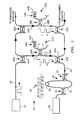
- a fiber optic sensor 20 includes a plurality of mismatched pathlength interferometers 22A, 22B, etc., which are shown to be Michelson interferometers.
- the fiber optic sensor 20 is not limited to the use of a Michelson interferometer, but may include any type of mismatched pathlength interferometer, such as a Mach-Zehnder interferometer.
- the structures and operational characteristics of both the Michaelson and Mach-Zehnder interferometers are described in detail subsequently.
- An optical signal source 24 which may be a laser diode, provides an optical signal to an optical fiber 26.
- the optical fiber 26 preferably has a cladding 28 surrounding a core 30 that guides a single mode of electromagnetic energy.
- the input signal propagates in the optical fiber 26 to a directional coupler 32A.
- a first portion of the optical signal incident upon the coupler 32A propagates through it, remaining in the fiber 26; and a second portion of the signal cross couples into an optical fiber 34A.
- the optical fiber 34A then guides the signal to an optical coupler 36A.
- the coupler 36A, an optical fiber 38A, a portion 40A of the optical fiber 34A extending through the coupler 36A and a mirror 42A attached to the end of the fiber portion 40A comprise the Michelson interferometer 22A.
- the interferometer 22A provides a signal to a fiber optic coupler 44A, which couples light between the fiber 38A and a receive fiber 46.
- the coupler 32A, the optical fiber 34A, the interferometer 22A, the optical fiber 38A and the coupler 44A comprise a leg 45A of the fiber optic sensor system 20.
- the signal coupled into the receive fiber 46 propagates to a processing Mach-Zehnder interferometer 48 that comprises an optical coupler 50, the receive fiber 46, an optical fiber 52, an optical coupler 54 and a phase modulator 56.
- the receive fiber 46 and the optical fiber 52 extend between the optical couplers 50 and 54.
- the phase modulator 56 is in the portion of the receive fiber 46 that is between the optical couplers 50 and 54.
- the optical coupler 50 couples part of the signal from the receive fiber 46 into the optical fiber 52.
- the optical coupler 54 combines the portion of the signal remaining in the receive fiber 46 with the portion that was coupled into the optical fiber 52.
- a detector 58 produces an electrical signal indicative of the interference pattern formed by the superposition of the optical signals guided by receive fiber 46 and optical fiber 52.
- the portion of the signal from the optical signal source 24 remaining in the optical fiber 26 beyond the coupler 32A propagates to a coupler 32B.
- the optical coupler 32B couples a portion of the light incident thereon into an optical fiber 34B, which guides the light to the Michelson interferometer 22B.
- the interferometer 22B comprises a coupler, a portion 40B of the fiber 34B, a mirror 42B on the end of the fiber portion 40B and an optical fiber 38B.
- the output of the interferometer 22B is input to a coupler 44B, which couples light from the interferometer 22B into the receive fiber 46.
- the optical coupler 32B the optical fiber 34B, the interferometer 22B, the optical fiber 38B and the coupler 44B comprise a leg 45B of the fiber optic sensor system 20.
- the fiber optic sensor system 20 may include any number of legs 45A, 45B, etc. with couplers 32A, 32B, etc., optical fibers 34A, 34B,etc., interferometers 22A, 22B, etc., optical fibers 38A, 38B, etc., and couplers 44A, 44B, etc.
- a preferred embodiment of the fiber optic sensor system 20 for use as an acoustic sensor includes eight such legs.
- All of the optical couplers 32, 36, 44, 50 and 54 may have substantially identical structures; therefore, the following description of the optical coupler 32A is applicable to all optical couplers included in the hydrophone system 20 when the optical fibers 26, 34, 38 46, 48 and 52 are single mode fibers.
- a symmetrical fiber optic directional coupler suitable for use in single mode fiber implementations of the invention is described in the March 29, 1980 issue of Electronics Letters , Vol. 18. pp. 260-261 and in U.S. Patent 4,493,518 issued January 15, 1985 to Shaw et al. That patent is assigned to the Board of Trustees of the Leland Stanford Junior University. The disclosure of of the patent is hereby incorporated by reference into this disclosure.
- optical power can be coupled between two optical fibers 26 and 34A by the evanescent fields that extend outside the cores.
- This effect has been used to make integrated-optic couplers where the dielectric waveguides can be fabricated in close enough proximity of evanescent coupling.
- the fiber 26 has a core 30 and a cladding 28, and the fiber 34A has a core 38 and a cladding 36.
- the evanescent field in optical fibers is buried deep within the fiber cladding to achieve low loss. Therefore, some of the claddings 28 and 36 must be removed to expose the evanescent fields of the guiding fiber core 30 and 38, respectively.
- the couplers used in the present invention may be formed by using a mechanical lapping technique to expose the evanescent fields.
- the optical fiber 26 is bonded into a curved slot 27 in a quartz block 29.
- the block 29 and fiber cladding 28 are then ground and polished to within a few microns of the fiber core 30.
- the polished block 29 and fiber 26 comprise a coupler half 77, and a polished block 39 and the fiber 34A comprise a coupler half 79. Placing the two coupler halves 77 and 79 in contact so that the polished faces confront each other places the cores 30 and 38 in close proximity.
- An index-matching oil is then inserted by a capillary action between the polished coupler halves 77 and 79 to match the cladding index to the refractive index of the block. This oil also acts as a lubricant to allow one coupler half to be slid over the other, as shown in Figure 6, to change the core-to-core separation and the net coupling.
- E i (z) is the complex field amplitude
- ⁇ is the optical frequency
- ⁇ is the fiber propagation constant
- c.c. is the complex conjugate.
- E(z) changes with z only in the coupling region.
- the vector a (x,z) is the modal field distribution normalized to unity:
- E2(z) jE1(0) sin kz + E2(0) cos kz.
- the coupling is not constant over the interaction region due to the curving of the fibers 26 and 34A.
- the coupling coefficient is a function of z with a maximum value of k o where the fibers are closest.
- This coupler can be considered as having an effective coupling length L c with a constant coupling coefficient k o given by
- the parameter of interest is the total coupled power.
- K o L c (1- ⁇ ) 1/2
- the amplitudes E1(0) and E3(0) can be regarded as the field amplitudes at two input ports, 1 and 3 while the amplitudes E2(L c ) and E4(L c ) can be the field amplitudes at the two output ports 2 and 4.
- Equation 14 the phase of the light in port 4 is greater than in port 2 by ⁇ /2 as indicated by the j factor in the expression for E4.
- the coupling of power from fiber 26 to fiber 34A occurs because the evanescent electric field in fiber 26 induces a linear polarization in fiber 34A at the optical frequency in phase with the evanescent electric field of fiber 26.
- the linear polarization in fiber 34A is the driving term in Maxwell's equations and generates an electromagnetic wave in fiber 34A that lags this polarization in time.
- the driving polarization and driven field in fiber 26 have the proper phase relationship for a power exchange from the induced polarization to the field.
- the cores 30 and 38 are sufficiently separated so that no coupling occurs.
- this offset is approximately 4 ⁇ m, 100% power transfer occurs.
- power is coupled back to the original guide (overcoupling).
- the coupling may be easily adjusted from 0 to 100%.
- the power insertion loss of these couples is low, ranging from 2% to 10%.
- the directivity is high (> 60dB) and the coupling ratio, once adjusted by the offset, is nearly independent of the input state of polarization.
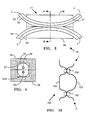
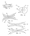
- Figure 10 shows a directional coupler 276 formed from a pair of single mode fibers 278 and 280 from which portions of the claddings have been lapped to permit the cores to be placed close enough together to permit evanescent coupling between waves guided by the two fiber cores.
- the fiber 280 is shown to have a core 282 that is smaller in diameter than the core 284 of the other fiber.
- the directional coupler 276 formed between the fibers 278 and 280 having different diameters of cores provides a higher coupling efficiency for light input to the smaller core 282.
- the interaction region of the fibers 278 and 280 is large enough so that the evanescent field of the light in the smaller core 282 interacts with the larger core 284 more effectively than the evanescent field of the light in the smaller core 282 interacts with the larger core 284.
- the smaller core diameter may be approximately 4 ⁇ , and the diameter of the larger core may be about 8 ⁇ .
- An important feature of the coupler configuration of Figure 10 is that part of the light from the larger core would be coupled into a cladding mode of the smaller fiber rather than coupling into the smaller core 282.
- the cladding modes may be stripped from the larger fiber by using a fiber having an absorbing jacket 286 formed around its cladding.
- a coupler 290 may be formed to have an asymmetric coupling region. Coupling occurs in the region of field overlap. The asymmetry of the coupling region provides more efficient coupling in one direction than in the other.
- Figure 12 is a side view of a coupler including an interaction region as shown in Figure 11.
- an asymmetric coupler 300 may be formed by placing a buffer layer film 302 between flattened portions on a pair of optical fibers 304 and 306.
- the buffer layer 302 is formed of a material that has greater loss for cross coupling in one direction across the interaction region than for the other direction.
- a fiber optic directional coupler 310 includes a wedge 312 formed of a crystalline material placed between the flattened portions of a pair of fibers 314 and 316.
- the wedge 312 makes the interaction region to the fibers asymmetrical about their centers of curvature. Therefore, coupling will be greater for light incident upon ports 1 and 2 than upon light incident upon ports 3 and 4.
- the Michelson interferometer 22A suitable for use as a sensor in the system 20 comprises the fiber optic directional coupler 36A and a sensing fiber coil 40A.
- the sensing fiber coil 40A terminates at the mirror 42A.
- Light from the laser 24 is coupled into the optical fiber 34A, which guides the light to port 1 of the coupler 36A. Part of the incident light propagates through the coupler 36A for output at port 2 to the sensing fiber coil 40A.
- the sensing coil 40A is exposed to the physical parameter being monitored.
- the mirror 42A reflects the input light signal back through the sensing coil 40A to port 2 of the coupler 36A.
- the coupler 36A couples a portion of the signal that has been exposed to the parameter being monitored into the fiber 38A. Changes in the parameter cause a phase shift in the light that has propagated through the sensing coil 40A.
- each leg of the array may include a Mach-Zehnder interferometer 100 that comprises a pair of optical fibers 102 and 104 and a pair of optical couplers 106 and 108 formed between the fibers 102 and 104.
- Light from the source (not shown) is coupled into the fiber 102 and propagated to the coupler 106 where a portion of the light couples into the fiber 104.
- the lengths of the fibers 102 and 104 between the couplers 106 and 108 are preferably different so that there is a phase difference between the light beams that traverse the two fibers. The beams combine in the coupler 108.
- the output signal at port 2 of the coupler 108 is a superposition of portions of the signals from the Mach-Zehnder interferometer 100.
- This interference pattern is a function of the phase difference between the beams in the two fibers.
- the phase difference is function of the lengths of the portions of the two fibers 102 and 104 between the couplers 106 and 108. Changes in the parameter being measured change the lengths of the fibers 102 and 104 and therefore change the phase difference.
- the coupling constants of the couplers 32A, 32B, etc. on the input optical fiber 26 and the coupling constants of the couplers 40A, 40B, etc. on the return fiber 46 are weighted such that each sensing interferometer 22A, 22B, etc. receives and returns an equal amount of optical power.
- an additional interferometer 48 is placed in the telemetry line either between the source and the first sensor or between the detector and the first sensor.
- Michelson interferometers could also be used.
- the optical path length difference existing at each sensor head at a particular instant of time is determined by sending a pulse of optical energy out on the telemetry fiber 46. A portion of the pulse is tapped off so that it enters each sensors head. At the sensor head coupler, one-half of the pulse is coupled into the long arm of the interferometer, and the remaining half propagates thru the short arm. In traversing the long and short paths, the light picks up the static phase delay existing at that instant of time.
- the pulse width is chosen such that two distinct, time-separated pulses of light exit from each sensor head. These pulse pairs are returned back toward the detector from each sensor head via a return telemetry fiber.
- the length of fiber linking each telemetry coupler must be greater than or equal to the pathlength difference of each sensor interferometer in order to prevent overlapping of pulses from successive sensors.
- the reference numeral 49 indicates the returning train of pulses is illustrated. Pulses are labeled S or L depending upon whether they traversed the short sensor arm of the long sensor arm, respectively. The numerical prefix associated with the retrun pulse train indicates from which sensor head each pulse pair is returning from.
- the S and L pulses must be superimposed in time and photodetected. Passing the pulse pairs through the serially connected interferometer 48 with a pathlength difference identical to the pathlength difference of the sensor head interferometers 22A, 22B, etc. accomplishes this function.
- This interferometer must be well-isolated from the both the field quantity being measured, and any disturbances that could cause a modulation of the pathlength difference in either the bandwidth or dynamic range of interest.
- a phase modulator 56 is placed in the long arm of the interferometer 48. It could be placed in either arm and operation would be equivalent.
- the modulator 56 is operated at a frequency outside the bandwith of the sensed information, yet no greater than one-half the optical pulse repetition rate. Pulses passing through the leg of the interferometer 48 that contains the phase modulator 56 pick up this high frequency, large amplitude modulation. When the pulse train is superimposed with a time-delayed (or time-advanced) replica of itself and photodetected, the information is shifted up away from the baseband and appears as modulation sidebands about the modulation frequency.
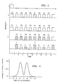
- Trace 1 is the input optical pulse.
- Trace 2 is the pulse train which enters the compensating interferometer 48.
- Trace 3 shows the output from this interferometer which traversed the short arm (top), and the long arm (bottom). Shading indicates that the carrier modulation was picked up as well. The lower trace is the resulting photodetected intensity resulting from the summation of these output pulse trains and subsequent photodetection.
- the distinct pulses labeled 1,2,3,... contain the sensed information.
- the pulses containing only the information from each sensor are sifted out with a 1:N multiplexer, where N is the number of sensors.
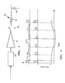
- the output of the fiber is incident upon the photodetector 58, which produces an electrical signal indicative of the intensity of the fiber optical output signal.
- the electrical output of the photodetector is input to a preamplifier 61.
- the amplified output then passes to a switch 63, which when closed allows the signal to pass through low pass filter 65 that comprises a resistor 67 adn a capacitor 69.
- B the carrier phase amplitude
- ⁇ m the carrier phase angular frequency
- s(t) the information of interest
- ⁇ o the static phase difference between recombining optical beams.
- each individual sensor is demodulated using any of several established demodulation methods.
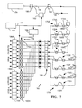
- a design for a multi-sensor vertical array 150 of fiber optic hydrophones is shown in Figure 7.
- the array 150 is powered with a 1.3 mm wavelength laser diode 154, which directly applies an optical signal to a first transmit fiber 156.
- a fiber optic directional coupler 158 couples light between the first transmit fiber 156 and a second transmit fiber 160.
- a second fiber optic directional coupler 164 is formed to couple light between the first and second transmit fibers after the second transmit fiber has passed through the frequency shifter 162.
- the directional coupler 164 couples light from the first transmit fiber into the second transmit fiber and couples part of the frequency shifted light from the second transmit fiber into the first transmit fiber. Therefore, both the first and second transmit fibers 156 and 160 guide signals of both the frequency ⁇ o of the laser diode and the shifted frequency ⁇ o + ⁇ .
- the examplary embodiment of Figure 7 includes eight sensing Mach-Zehnder interferometers 170A-170H.
- the transmit fiber 160 guides light to the first four sensing interferometers 170A-170D of the eight sensor array.
- Light from the transmit fiber 160 impinges upon a plurality of optical couplers 166A-166C, which couple light into corresponding fibers 168A-168C that form parts of a plurality Mach-Zehnder interferometers 170A-170C.
- Light remaining in the fiber 160 is guided to an optical coupler 172D that forms part of a Mach-Zehnder interferometer 170D.
- the Mach-Zehnder interferometer 170A also includes a pair of couplers 172A and 174A and an optical fiber 176A. Portions of the fiber 168A and 176A between the couplers 172A and 174A have different optical path lengths. Therefore, there is an interference pattern formed when the signals carried by the fibers 168A and 176A recombine in the coupler 174A. An acoustic wave incident upon the fibers causes changes in the path lengths, which changes the intereference pattern. These changes may be monitored to determine the amplitude of the acoustic wavefront.
- the transmit fiber 156 guides light to couplers 166E, 166F and 166G, which couple light into fibers 168E, 168F and 168G, respectively. These fibers then guide light to Mach-Zehnder interferometers 170E, 170F and 170G, respectively, that comprise couplers 166E, 166F and 166G and optical fibers 176E, 176F and 176G. The light remaining in the second transmit fiber is then directly input to the Mach-Zehnder interferometer 170H via the coupler 172H.
- the Mach-Zehnder interferometers 170B-170H are formed similarly to the Mach-Zehnder interferometer 170A.
- the Mach-Zehnder interferometers 170B-170H therefore include couplers 172B-172H, couplers 174B-174H and fibers 176B-176H connected in the same manner as described above for the Mach-Zehnder interferometer 170A.
- the fibers 160, 168A-168F and 156 guide the signals output from the Mach-Zehnder interferometers 170A-170H to a photodiode array 174.
- the photodiode array 174 includes a plurality of photodiodes so that the output of each interferometer impinges upon a corresponding photodiode.
- the photodiode array 174 converts the optical signals output from the interferometers 170A-170H into corresponding electrical signals.
- a preamplifier array 176 receives the electrical signals output from the photodiode array 174.
- the preamplifier 176 includes a plurality of preamplifiers connected to the photodiodes 174A, 174B, etc., respectively, so that the output of each photodiode is input to a preamplifier.
- the signals output from the preamplifier array 176 are input to a pair of mixer arrays 178 and 180.
- the output of the preamplifier 176A is input to a mixer 178A and a mixer 180A.
- the outputs of the preamplifiers 176B, 176C, etc. are input to mixers 178B and 180B, 178C and 180C, etc.
- a radio frequency oscillator 182 drives the frequency shifter 162 and the mixer array 180.
- the output of the oscillator 182 is also input to a 90° phase shifter 184, which has a output connected to the mixer array 178. Therefore, the mixer arrays 178 and 180 are driven in quadrature.
- the outputs of the mixer array 178 are input to a low pass filter array 186, which contains a plurality of low pass filters 186A, 186B, etc.
- the outputs of the mixers 180A, 180B, etc. are input to the low pass filters 188A, 188B, etc., respectively.
- the low pass filters 186A, 186B, etc. are proportional to the sines of the phase shifts of the interferometers.
- the outputs of the mixers 180A, 180B, etc. are input to a low pass filter array 188, which contains a plurality of low pass filters 188A, 188B, etc.
- the low pass filters 186A, 186B, etc. are proportional to the cosines of the phase shifts of the interferometers.
- Each photodiode output is amplified in a separate preamplifier, as shown in Figure 7.
- Each preamp output then feeds a pair of electronic mixers.
- the signal is mixed with an in-phase replica of the RF oscillator in one mixer, and a quadrature replica in the other.
- the mixer outputs result in the sin ⁇ and cos ⁇ of the sensor-induced phase modulation, which is a direct result of the acoustic signal.
- each hydrophone there is a sin ⁇ output and cosine ⁇ output. All of the outputs are then multiplexed onto the telemetry during each sampling interval, which, for a 500 Hz bandwidth, will be approximately 1 ms.
- the laser diode 154 is operated continuously (CW).
- the light input to the fiber 156 is immediately split equally with thea 2 x 2 fiber optic coupler 158 and directed simultaneously into a short (S) and a long (L) path.
- the outputs from these paths are recombined in the second 2x2 coupler 164.
- the pathlength difference is generally on the order of a few tens of meters.
- the in-line fiber optic frequency shifter 162 performs the function of determining the optical pathlength difference between the couplers 158 and 164.
- a phase modulator 200 driven by a sawtooth wave can be substituted for the frequency shifter.
- Fiber optic frequency shifters are described subsequently with reference to Figures 16-22 and the phase modulator 200 is described with reference to Figures 23-25.
- the second coupler 164 has two identical outputs, each of which carries half of the power from the short and long fiber paths. Each line is used to power one-half of the sensors in the array.
- the cable connecting the laser source 154 to the sensors is 1 km long.
- single mode fiber cables exhibiting losses less than 0.5 dB/km are available so power loss in the cable is essentially negligible.
- Each individual sensor receives a fraction of the total optical power via the fiber optic coupler 164 from one of the two output lines 156 or 160.
- the optimum power deliverable to each sensor has been calculated.
- the optimum power in decibels referred to the input is approximately -10 log N, where N is the number of interfeometers in the system. Results are presented in Table 1 for various values of N. Because the fiber path between couplers is so short that fiber losses are negligible, a finite loss of 0.1 dB per coupler is assumed. In addition to the delivery loss, a 3 dB loss is taken at each sensor because only one of the sensor's two outputs is being utilized. This is included in the numbers shown in Table 1.
- the frequency shifter 162 must be isolated from the environment, since signals or other pressures acting upon it could produce optical phase shifts that would be indistinguishable from those affecting the sensing interferometers 170A-170G.
- the entire predelay network including the couplers 158, the frequency shifter 162 and the coupler 164 are preferably sealed within a rigid cannister (not shown).
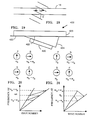
- Figure 16 illustrates the effect of a frequency shifter on an optical wave.
- a frequency shifter on an optical wave.
- the input wave is shown to have a frequency f o .
- the wave is traveling in the positive z-direction and has polarization vectors along the x- and y-axes that are of equal magnitude and 90° out of phase. Therefore, the polarization vector appears to rotate at angular velocity f o about the z-axis in a clockwise direction when viewed looking toward the direction of propagation.
- the half-wave plate 400 rotates in the same direction as the polarization vector so that the output wave frequency shifted from the input frequency f o to have a frequency of f o + 2f.
- Figure 17 graphically represents the possible frequency outputs from the frequency shifter 162 when it is operated as a single-side-band-suppressed-carrier phase shifter. If the input frequency is f o , then rotating the half-wave plate at frequency f in the direction of polarization of the input beam produces an output of f o - 2f. Controlling the rotational frequency f permits the output frequency of the quarter-wave plate to have a range of f o ⁇ 2f max is the maximum rotational frequency of the half-wave plate 400.
- 2 (18) A2 + B2 + 2AB cos (2ft). (19)
- the coefficient A is ordinarily much larger than B so that B2 is negligible.
- the frequency shifter 162 may include a length 422 of the optical fiber 160 retained between a block 423 that may be formed of quartz and a wedge 424 formed of a material such as aluminum.
- a metallic layer comprising Cr-Au, for example, is formed on the surface 427 of the wedge 424, and a transducer 430 formed of PZT, for example, is mounted to the metallic block 424.
- the transducer 430 may be driven by a suitable oscillator (not shown) to launch an acoustic wave at an angle ⁇ in the fiber.
- the fiber 162 being a single mode fiber, supports two orthogonal polarizations of the single propagation mode. There are two polarizations because the fiber is birefringent, having different refractive indices for different directions of the electric field in the fiber. The two polarizations are normally uncoupled so that there is no energy transfer from one polarization to the other. A spatially periodic stress pattern imposed on the fiber induces coupling between the two polarizations, leading to power transfer therebetween. It has been found that the power transfer is cumulative only if the spatial period of the stress pattern equals the beat length of the fiber.
- the transducer 430 forms a moving stress pattern in the fiber portion 422 by means of the traveling acoustic wave. If the stress pattern moves along the fiber, light coupled from one polarization to the other is shifted in frequency by an amount equal to the frequency of the moving stress pattern because of the motion of the coupling region.
- one of the polarizations will be referred to as "slow;” and the other polarization will be referred to as "fast.”
- the frequency shifter 420 is a single side band frequency shifter if only light of a single polarization impinges upon the portion of the fiber 162 having the periodic moving the stress pattern therein.
- the selected polarization may have small amounts of the carrier frequency and the sideband having the opposite frequency shift because of the finite extinction ratio of the polarizers included in the gyroscope and other factors.
- a frequency shifter 450 that may be included in the array 150 comprises a length of the fiber 162 mounted in a grooved substrate 452.
- An electrode 454 is mounted in the groove 456 below the fiber 162.
- a portion of the fiber cladding 460 is ground away to form an interaction region 461 near the core 462.
- An interaction material 464 formed of an electrooptically active material is mounted on the region of the fiber where the cladding was removed.
- a pair of electrodes 466 and 468 are mounted on opposite ends of the interaction material, and an electrode 470 is mounted on the interaction material in generally parallel alignment with the electrode 456.
- An oscillator 472 supplies voltage to the electrode 470.
- a phase shifter receives the oscillator output, shifts its phase and then applies the phase shifted signal to the electrode 468. the electrodes 466 and 456 are grounded.
- the phase modulator 200 may comprise an optical waveguide 470 formed on a substrate 472 of an electrooptically active material such as lithium niobate.
- a pair of electrodes 474 and 476 are attached to the substrate 472 on opposite sides of the waveguide 470.
- the electrodes 474 and 476 may be formed on the substrate 472 by vapor deposition of aluminum.
- the optical waveguide 470 may be formed in the substrate 472 by first depositing a strip of titanium on the substrate 480 and heating it to drive the titanium into the substrate 472.
- the resulting waveguide 470 has a generally semicircular cross section as shown in Figure 24.
- the fiber 162 must be cut to have two ends 162A and 162B that are butt coupled to opposite sides of the optical waveguide 470 as shown in Figures 23 and 24.
- the transit time of a light wave through the waveguide 21 is the product of the length of the waveguide and its refractive index divided by the speed of light in vacuum. Changing the refractive index of the optical waveguide 21 thus changes the transit time of an optical signal through it. Because of the sinusoidal nature of the electroomagnetic fields that comprise the light wave, the change in transit time is seen as a change in phase of the wave.
Landscapes
- Physics & Mathematics (AREA)
- General Physics & Mathematics (AREA)
- Life Sciences & Earth Sciences (AREA)
- Engineering & Computer Science (AREA)
- Analytical Chemistry (AREA)
- Chemical & Material Sciences (AREA)
- Optics & Photonics (AREA)
- Acoustics & Sound (AREA)
- Environmental & Geological Engineering (AREA)
- Geology (AREA)
- Remote Sensing (AREA)
- General Life Sciences & Earth Sciences (AREA)
- Geophysics (AREA)
- Instruments For Measurement Of Length By Optical Means (AREA)
- Measurement Of Mechanical Vibrations Or Ultrasonic Waves (AREA)
Applications Claiming Priority (2)
| Application Number | Priority Date | Filing Date | Title |
|---|---|---|---|
| US07/009,922 US4848906A (en) | 1987-02-02 | 1987-02-02 | Multiplexed fiber optic sensor |
| US9922 | 1987-02-02 |
Publications (3)
| Publication Number | Publication Date |
|---|---|
| EP0277699A2 true EP0277699A2 (fr) | 1988-08-10 |
| EP0277699A3 EP0277699A3 (en) | 1988-12-07 |
| EP0277699B1 EP0277699B1 (fr) | 1991-12-27 |
Family
ID=21740508
Family Applications (1)
| Application Number | Title | Priority Date | Filing Date |
|---|---|---|---|
| EP88300079A Expired EP0277699B1 (fr) | 1987-02-02 | 1988-01-06 | Détecteur multiplexé à fibres optiques |
Country Status (3)
| Country | Link |
|---|---|
| US (1) | US4848906A (fr) |
| EP (1) | EP0277699B1 (fr) |
| CA (1) | CA1320356C (fr) |
Cited By (17)
| Publication number | Priority date | Publication date | Assignee | Title |
|---|---|---|---|---|
| WO1989011110A1 (fr) * | 1988-05-12 | 1989-11-16 | The Commonwealth Of Australia Of Department Of Def | Reseau de fibres optiques interferometrique |
| EP0529339A1 (fr) * | 1991-08-29 | 1993-03-03 | Asea Brown Boveri Ag | Capteur à fibre optique |
| EP1052482A3 (fr) * | 1999-05-10 | 2002-05-22 | Litton Systems, Inc. | Procédé de normalisation amélioré pour systèmes de capteurs fibre-optiques |
| WO2005008173A1 (fr) * | 2003-07-15 | 2005-01-27 | Robert Bosch Gmbh | Dispositif de mesure optique |
| US20120147924A1 (en) * | 2010-12-08 | 2012-06-14 | Baker Hughes Incorporated | System and method for distributed environmental parameter measurement |
| CN103090961A (zh) * | 2013-02-01 | 2013-05-08 | 华中科技大学 | 一种分布式光纤传感系统的扰动源定位方法 |
| US8455844B2 (en) | 2009-03-11 | 2013-06-04 | Colorado State University Research Foundation | System and method for time-division multiplexed optical sensing of biosensors |
| CN103824422A (zh) * | 2012-11-19 | 2014-05-28 | 同方威视技术股份有限公司 | 铁路沿线危岩落石监控报警系统 |
| EP2598918A4 (fr) * | 2010-07-26 | 2016-03-30 | Geco Technology Bv | Utilisation d'un capteur acoustique distribué à fibres optiques pour positionner un objet |
| US9493805B2 (en) | 2001-06-01 | 2016-11-15 | Colorado State University Research Foundation | Enzymatic biosensors with enhanced activity retention for detection of organic compounds |
| US9493806B2 (en) | 2001-06-01 | 2016-11-15 | Colorado State University Research Foundation | Enzymatic biosensing systems |
| US9796998B2 (en) | 2007-04-09 | 2017-10-24 | Colorado State University Research Foundation | Oxygenase-based biosensing systems for measurement of halogenated alkene concentrations |
| US9896712B2 (en) | 2011-08-02 | 2018-02-20 | Colorado State University Research Foundation | Biosensing system with extended lifetime via cofactor recycling |
| US10024797B2 (en) | 2010-11-22 | 2018-07-17 | Colorado State University Research Foundation | Biosensing systems for measurement of lactose |
| CN111947765A (zh) * | 2020-07-13 | 2020-11-17 | 深圳华中科技大学研究院 | 一种基于微结构光纤水听拖曳缆的全分布式水声传感系统 |
| CN112033521A (zh) * | 2020-08-07 | 2020-12-04 | 太原理工大学 | 一种本地噪声自滤除的混合式光纤振动传感系统 |
| CN112903083A (zh) * | 2019-12-04 | 2021-06-04 | 中国科学院上海光学精密机械研究所 | 基于多模光纤的高信噪比声传感器 |
Families Citing this family (37)
| Publication number | Priority date | Publication date | Assignee | Title |
|---|---|---|---|---|
| US4972077A (en) * | 1988-08-08 | 1990-11-20 | Schlumberger Industries Limited | Wavelength multiplexed optical transducer with a swept wavelength optical source |
| US5039221A (en) * | 1989-07-03 | 1991-08-13 | Litton Systems, Inc. | Interferometer calibration for fiber optic sensor arrays |
| DK124690D0 (da) * | 1990-05-18 | 1990-05-18 | Henning Rud Andersen | Klapprotes til implantering i kroppen for erstatning af naturlig klap samt kateter til brug ved implantering af en saadan klapprotese |
| US5475216A (en) * | 1990-05-22 | 1995-12-12 | Danver; Bruce A. | Fiber optic sensor having mandrel wound reference and sensing arms |
| US5155548A (en) * | 1990-05-22 | 1992-10-13 | Litton Systems, Inc. | Passive fiber optic sensor with omnidirectional acoustic sensor and accelerometer |
| US5140154A (en) * | 1991-01-16 | 1992-08-18 | The United States Of America As Represented By The Secretary Of The Navy | Inline fiber optic sensor arrays with delay elements coupled between sensor units |
| US5119679A (en) * | 1991-04-05 | 1992-06-09 | The Boeing Company | Optically powered and linked pressure transducer |
| US5194847A (en) * | 1991-07-29 | 1993-03-16 | Texas A & M University System | Apparatus and method for fiber optic intrusion sensing |
| US5294075A (en) * | 1991-08-28 | 1994-03-15 | The Boeing Company | High accuracy optical position sensing system |
| US5201015A (en) * | 1991-09-19 | 1993-04-06 | Litton Systems, Inc. | Conformal fiber optic strain sensor |
| US5297224A (en) * | 1992-08-14 | 1994-03-22 | Litton Systems, Inc. | Optically switched sensor array |
| JPH06117961A (ja) * | 1992-10-05 | 1994-04-28 | Furukawa Electric Co Ltd:The | 光線路監視方法 |
| US5473459A (en) * | 1993-12-03 | 1995-12-05 | Optimux Systems Corporation | Optical telecommunications system using phase compensation interferometry |
| KR100217714B1 (ko) * | 1993-12-31 | 1999-09-01 | 윤종용 | 레이저 다이오드가 결합된 간섭형 광온도 센싱 시스템 |
| US5459600A (en) * | 1994-03-08 | 1995-10-17 | Optimux Systems Corporation | Optical telecommunications system employing multiple phase-compensated optical signals |
| GB9605144D0 (en) * | 1996-03-11 | 1996-05-08 | Sensor Dynamics Ltd | Apparatus for sensing one or more parameters |
| US5737278A (en) * | 1996-06-17 | 1998-04-07 | Litton Systems, Inc. | Extended, flexible, spatially weighted fiber optic interferometric hydrophone |
| US5696857A (en) * | 1996-07-25 | 1997-12-09 | Litton Systems, Inc. | WDM/FDM fiber optic sensor architecture using WDM tap coupler |
| US6072921A (en) * | 1997-07-18 | 2000-06-06 | Litton Systems, Inc. | Method of operating a fiber-optic acoustical sensor, apparatus for practicing the method, and in-line fiber-optic polarizer usable in such apparatus |
| GB9721473D0 (en) | 1997-10-09 | 1997-12-10 | Sensor Dynamics Ltd | Interferometric sensing apparatus |
| DE29811436U1 (de) * | 1998-06-26 | 1999-10-28 | Robert Bosch Gmbh, 70469 Stuttgart | Elektrische Maschine, insbesondere flüssigkeitsgekühlter Drehstromgenerator |
| US6346985B1 (en) | 1999-10-29 | 2002-02-12 | Litton Systems, Inc. | Optical method for the transduction of remote arrays of electromechanical sensors |
| US6606186B2 (en) | 2001-07-25 | 2003-08-12 | Pgs Americas, Inc. | Dynamic fiber optic sensor signal processing scheme |
| WO2004073501A2 (fr) * | 2003-02-20 | 2004-09-02 | Gutin Mikhail | Tomographie par coherence optique avec balayage par coherence 3d |
| US6827597B1 (en) | 2003-11-20 | 2004-12-07 | Pgs Americas, Inc. | Combined electrical and optical cable connector particularly suited for marine seismic sensor streamers |
| US20060152383A1 (en) * | 2004-12-28 | 2006-07-13 | Tsutomu Yamate | Methods and apparatus for electro-optical hybrid telemetry |
| US7499176B2 (en) * | 2007-02-13 | 2009-03-03 | Future Fibre Technologies Pty Ltd | Apparatus and method for using a counter-propagating signal method for locating events |
| WO2006074502A1 (fr) * | 2005-01-11 | 2006-07-20 | Future Fibre Technologies Pty Ltd | Dispositif et procede pour l'utilisation de signaux de contre-propagation permettant la localisation d'evenements |
| US7327462B2 (en) * | 2005-08-17 | 2008-02-05 | Litton Systems, Inc. | Method and apparatus for direct detection of signals from a differential delay heterodyne interferometric system |
| GB0705240D0 (en) * | 2007-03-14 | 2007-04-25 | Qinetiq Ltd | Phase based sensing |
| GB0815523D0 (en) * | 2008-08-27 | 2008-10-01 | Qinetiq Ltd | Phase based sensing |
| GB0917150D0 (en) | 2009-09-30 | 2009-11-11 | Qinetiq Ltd | Phase based sensing |
| EP2472750A1 (fr) * | 2010-12-30 | 2012-07-04 | Nokia Siemens Networks Oy | Système et procédé de réseau optique |
| US9677957B2 (en) * | 2012-11-27 | 2017-06-13 | Senek Instrument LLC | Serial fiber Bragg grating interrogator with a pulsed laser for reflection spectrum measurement |
| WO2015094343A1 (fr) | 2013-12-20 | 2015-06-25 | Halliburton Energy Services, Inc. | Capteurs optiques d'outils de diagraphie de fond |
| US9970819B2 (en) * | 2015-03-23 | 2018-05-15 | Si-Ware Systems | High performance parallel spectrometer device |
| CN114777898B (zh) * | 2022-03-28 | 2024-03-26 | 中国人民解放军国防科技大学 | 一种对称时分复用结构及高可靠光纤水听器阵列系统 |
Family Cites Families (12)
| Publication number | Priority date | Publication date | Assignee | Title |
|---|---|---|---|---|
| US3990036A (en) * | 1974-02-28 | 1976-11-02 | Western Geophysical Co. | Multiplexing method and apparatus for telemetry of seismic data |
| AU4223778A (en) * | 1977-12-12 | 1979-06-21 | Pedro B Macedo | Optical waveguide sensor |
| JPS5621004A (en) * | 1979-07-30 | 1981-02-27 | Toshiba Corp | Optical sensing system |
| US4443700A (en) * | 1980-02-01 | 1984-04-17 | Pedro B. Macedo | Optical sensing apparatus and method |
| US4360272A (en) * | 1980-03-20 | 1982-11-23 | Optelecom, Inc. | Fiber optic energy sensor and optical demodulation system and methods of making same |
| GB2096762A (en) * | 1981-04-09 | 1982-10-20 | Univ London | Optical fibre sensor device |
| DE3224775A1 (de) * | 1981-06-30 | 1983-01-20 | Hahn-Meitner-Institut für Kernforschung Berlin GmbH, 1000 Berlin | Ueberwachungssystem fuer betriebsanlagen |
| US4505587A (en) * | 1981-08-14 | 1985-03-19 | Massachusetts Institute Of Technology | Picosecond optical sampling |
| US4588296A (en) * | 1981-10-07 | 1986-05-13 | Mcdonnell Douglas Corporation | Compact optical gyro |
| US4436425A (en) * | 1982-03-29 | 1984-03-13 | The United States Of America As Represented By The Secretary Of The Navy | Signal waveform detector using synthetic FM demodulation |
| US4552457A (en) * | 1983-02-01 | 1985-11-12 | Giallorenzi Thomas G | Fiber optic interferometer using two wavelengths or variable wavelength |
| US4697926A (en) * | 1985-02-08 | 1987-10-06 | The Board Of Trustees Of The Leland Stanford Junior University | Coherent distributed sensor and method using short coherence length sources |
-
1987
- 1987-02-02 US US07/009,922 patent/US4848906A/en not_active Expired - Lifetime
- 1987-12-21 CA CA000554976A patent/CA1320356C/fr not_active Expired - Fee Related
-
1988
- 1988-01-06 EP EP88300079A patent/EP0277699B1/fr not_active Expired
Non-Patent Citations (2)
| Title |
|---|
| ELECTRONICS LETTERS, vol. 16, no. 7, 27th March 1980, pages 260-261, Hitchen, Herts, GB; R.A. BERGH et al.: "Single-mode fibre optic directional coupler" * |
| OPTICS LETTERS, vol. 11, no. 7, July 1986, pages 473-475, Optical Society of America, New York, US; J.L. BROOKS et al.: "Fiber-optic interferometric sensor arrays with freedom from source phase-induced noise" * |
Cited By (22)
| Publication number | Priority date | Publication date | Assignee | Title |
|---|---|---|---|---|
| AU613497B2 (en) * | 1988-05-12 | 1991-08-01 | Commonwealth of Australia of Department of Defence, The | An interferometric fibre optic network |
| EP0417162A4 (en) * | 1988-05-12 | 1992-12-16 | The Commonwealth Of Australia Defence | An interferometric fibre optic network |
| WO1989011110A1 (fr) * | 1988-05-12 | 1989-11-16 | The Commonwealth Of Australia Of Department Of Def | Reseau de fibres optiques interferometrique |
| EP0529339A1 (fr) * | 1991-08-29 | 1993-03-03 | Asea Brown Boveri Ag | Capteur à fibre optique |
| EP1052482A3 (fr) * | 1999-05-10 | 2002-05-22 | Litton Systems, Inc. | Procédé de normalisation amélioré pour systèmes de capteurs fibre-optiques |
| US9493805B2 (en) | 2001-06-01 | 2016-11-15 | Colorado State University Research Foundation | Enzymatic biosensors with enhanced activity retention for detection of organic compounds |
| US9493806B2 (en) | 2001-06-01 | 2016-11-15 | Colorado State University Research Foundation | Enzymatic biosensing systems |
| WO2005008173A1 (fr) * | 2003-07-15 | 2005-01-27 | Robert Bosch Gmbh | Dispositif de mesure optique |
| US9796998B2 (en) | 2007-04-09 | 2017-10-24 | Colorado State University Research Foundation | Oxygenase-based biosensing systems for measurement of halogenated alkene concentrations |
| US8455844B2 (en) | 2009-03-11 | 2013-06-04 | Colorado State University Research Foundation | System and method for time-division multiplexed optical sensing of biosensors |
| EP2598918A4 (fr) * | 2010-07-26 | 2016-03-30 | Geco Technology Bv | Utilisation d'un capteur acoustique distribué à fibres optiques pour positionner un objet |
| US10024797B2 (en) | 2010-11-22 | 2018-07-17 | Colorado State University Research Foundation | Biosensing systems for measurement of lactose |
| US20120147924A1 (en) * | 2010-12-08 | 2012-06-14 | Baker Hughes Incorporated | System and method for distributed environmental parameter measurement |
| US8740455B2 (en) * | 2010-12-08 | 2014-06-03 | Baker Hughes Incorporated | System and method for distributed environmental parameter measurement |
| US9896712B2 (en) | 2011-08-02 | 2018-02-20 | Colorado State University Research Foundation | Biosensing system with extended lifetime via cofactor recycling |
| CN103824422B (zh) * | 2012-11-19 | 2017-03-08 | 同方威视技术股份有限公司 | 铁路沿线危岩落石监控报警系统 |
| CN103824422A (zh) * | 2012-11-19 | 2014-05-28 | 同方威视技术股份有限公司 | 铁路沿线危岩落石监控报警系统 |
| CN103090961A (zh) * | 2013-02-01 | 2013-05-08 | 华中科技大学 | 一种分布式光纤传感系统的扰动源定位方法 |
| CN112903083A (zh) * | 2019-12-04 | 2021-06-04 | 中国科学院上海光学精密机械研究所 | 基于多模光纤的高信噪比声传感器 |
| CN111947765A (zh) * | 2020-07-13 | 2020-11-17 | 深圳华中科技大学研究院 | 一种基于微结构光纤水听拖曳缆的全分布式水声传感系统 |
| CN112033521A (zh) * | 2020-08-07 | 2020-12-04 | 太原理工大学 | 一种本地噪声自滤除的混合式光纤振动传感系统 |
| CN112033521B (zh) * | 2020-08-07 | 2022-03-15 | 太原理工大学 | 一种本地噪声自滤除的混合式光纤振动传感系统 |
Also Published As
| Publication number | Publication date |
|---|---|
| CA1320356C (fr) | 1993-07-20 |
| EP0277699B1 (fr) | 1991-12-27 |
| EP0277699A3 (en) | 1988-12-07 |
| US4848906A (en) | 1989-07-18 |
Similar Documents
| Publication | Publication Date | Title |
|---|---|---|
| US4848906A (en) | Multiplexed fiber optic sensor | |
| US4697926A (en) | Coherent distributed sensor and method using short coherence length sources | |
| JP2578601B2 (ja) | 環境の変化を遠隔的に感知するためのセンサシステム・センサアレイおよび方法 | |
| KR870001580B1 (ko) | 수동 간섭계식 감지기 어레이 | |
| US4699513A (en) | Distributed sensor and method using coherence multiplexing of fiber-optic interferometric sensors | |
| EP0277698B1 (fr) | Méthode et arrangement de mesure avec des détecteurs fibreoptiques | |
| CA2278356C (fr) | Groupe-capteur de guides d'ondes optiques pour la detection a distance | |
| EP0197621B1 (fr) | Gyroscope à fibre optique avec propagation d'une fréquence différentielle | |
| CA1258383A (fr) | Senseur interferometrique a fibre passive commute par les variations de longeur d'onde | |
| US4784453A (en) | Backward-flow ladder architecture and method | |
| US4767210A (en) | Optical fibre interferometer | |
| US5991026A (en) | Apparatus for multiplexing fibre-optic sensing interferometers | |
| JPH059769B2 (fr) | ||
| US4882716A (en) | Optic fiber hydrophone and antenna associating a series of hydrophones | |
| US5039221A (en) | Interferometer calibration for fiber optic sensor arrays | |
| De Paula et al. | Fiber optic sensor overview | |
| US4944591A (en) | Double phase-conjugate fiber optic gyroscope | |
| CN1307404C (zh) | 基于马赫-曾德尔干涉原理的干涉式光纤陀螺仪 | |
| CN114370928A (zh) | 一种直线型萨格纳克干涉式光纤振动传感器 | |
| JPS61202116A (ja) | 光フアイバジヤイロ | |
| EP0507742A1 (fr) | Capteur optique de courant électrique | |
| RU2087859C1 (ru) | Устройство для регистрации изменения оптической длины волоконного интерферометра | |
| Keur et al. | Single Mode Fiber Optic DC Magnetometer Capable Of Multiple-Point Measurement | |
| Davies | IEE Electronics Division: Chairman's address. Making measurements with light | |
| JACKSON | PHYSICS LABORATORY, UNIVERSITY OF KENT, CANTERBURY, KENT CT2 7NR, UK. |
Legal Events
| Date | Code | Title | Description |
|---|---|---|---|
| PUAI | Public reference made under article 153(3) epc to a published international application that has entered the european phase |
Free format text: ORIGINAL CODE: 0009012 |
|
| AK | Designated contracting states |
Kind code of ref document: A2 Designated state(s): FR GB |
|
| PUAL | Search report despatched |
Free format text: ORIGINAL CODE: 0009013 |
|
| AK | Designated contracting states |
Kind code of ref document: A3 Designated state(s): FR GB |
|
| 17P | Request for examination filed |
Effective date: 19890522 |
|
| 17Q | First examination report despatched |
Effective date: 19900726 |
|
| GRAA | (expected) grant |
Free format text: ORIGINAL CODE: 0009210 |
|
| AK | Designated contracting states |
Kind code of ref document: B1 Designated state(s): FR GB |
|
| ET | Fr: translation filed | ||
| PLBE | No opposition filed within time limit |
Free format text: ORIGINAL CODE: 0009261 |
|
| STAA | Information on the status of an ep patent application or granted ep patent |
Free format text: STATUS: NO OPPOSITION FILED WITHIN TIME LIMIT |
|
| 26N | No opposition filed | ||
| REG | Reference to a national code |
Ref country code: GB Ref legal event code: IF02 |
|
| PGFP | Annual fee paid to national office [announced via postgrant information from national office to epo] |
Ref country code: GB Payment date: 20070125 Year of fee payment: 20 |
|
| REG | Reference to a national code |
Ref country code: GB Ref legal event code: PE20 |
|
| PGFP | Annual fee paid to national office [announced via postgrant information from national office to epo] |
Ref country code: FR Payment date: 20070117 Year of fee payment: 20 |
|
| PG25 | Lapsed in a contracting state [announced via postgrant information from national office to epo] |
Ref country code: GB Free format text: LAPSE BECAUSE OF EXPIRATION OF PROTECTION Effective date: 20080105 |