EP0277883A2 - Dispositif de déflexion holographique - Google Patents
Dispositif de déflexion holographique Download PDFInfo
- Publication number
- EP0277883A2 EP0277883A2 EP88400248A EP88400248A EP0277883A2 EP 0277883 A2 EP0277883 A2 EP 0277883A2 EP 88400248 A EP88400248 A EP 88400248A EP 88400248 A EP88400248 A EP 88400248A EP 0277883 A2 EP0277883 A2 EP 0277883A2
- Authority
- EP
- European Patent Office
- Prior art keywords
- hologram
- deflection device
- diffraction
- light
- holographic deflection
- Prior art date
- Legal status (The legal status is an assumption and is not a legal conclusion. Google has not performed a legal analysis and makes no representation as to the accuracy of the status listed.)
- Granted
Links
Images


Classifications
-
- G—PHYSICS
- G02—OPTICS
- G02B—OPTICAL ELEMENTS, SYSTEMS OR APPARATUS
- G02B5/00—Optical elements other than lenses
- G02B5/32—Holograms used as optical elements
-
- G—PHYSICS
- G02—OPTICS
- G02B—OPTICAL ELEMENTS, SYSTEMS OR APPARATUS
- G02B26/00—Optical devices or arrangements for the control of light using movable or deformable optical elements
- G02B26/08—Optical devices or arrangements for the control of light using movable or deformable optical elements for controlling the direction of light
- G02B26/0808—Optical devices or arrangements for the control of light using movable or deformable optical elements for controlling the direction of light by means of one or more diffracting elements
Definitions
- the present invention relates to an optical deflection device. More precisely, it relates to a holographic deflection device by which the deflection angle can be controlled only be controlling the wavelength of the length beam source and it is not necessary to move the lens.
- the deflection angle is usually controlled by a mechanical displacement of a rotating polygon mirror or an oscillating mirror by a motor. It is also known to use a hologram scanner in which a hologram is mechanically moved.
- optical deflector which incorporates a solid element, such as an acoustooptic element, but this optical deflector can realize only a small deflection angle and thus has only a limited use.
- the inventors of the present invention decided to investigate a non-mechanical control of the deflection angle.
- the primary object of the present invention is to provide an optical deflection device by which the deflection angle can be optically controlled without moving the lens or mirror.
- an optical deflection device which comprises a tunable semiconductor laser, in which the wavelength of the beam emitted therefrom can be varied, and at least one hologram lens which is inclined from the optical axis at a predetermined angle, whereby the deflection angle can be controlled by changing the wavelength of the laser beam incident upon the hologram.
- the diffraction grating can be changed by only a change in the wavelength of the laser beam, resulting in an easy control of the deflection angle of the laser beam by the hologram.
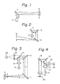
- the device essentially comprises a hologram lens 11 having a focal length depending on the wavelength of the beam transmitted therethrough, and a tunable laser 13.
- the hologram lens 11 as is well known, converges light by a diffraction effect and this function is largely dependent upon the wavelength of the beam.
- the hologram lens 11 is inclined from the optical axis X of the tunable laser 13 at a predetermined angle , so that when the wavelength of the laser beam incident upon the hologram lens 11 varies, the deflection angle of the hologram lens 11 also varies, as shown by an imaginary line.
- the present invention utilizes this characteristic of the hologram lens to realize a laser scanner which can scan the laser beam only by controlling the wavelength of the laser beam and without a mechanical displacement of the hologram lens 11. Note that, when the present invention is applied to a deflection device unable to carry out beam scanning, the hologram lens 11 can be replaced by a common plane hologram having plane relief type gratings and not able to converge light.
- the focal length of the hologram changes slightly, in addition to the change of the deflection angle, when the wavelength of the laser beam is changed, as is well known, and accordingly, this should be taken into consideration when the position of the image plane M is determined.
- the deflection angle can be determined by the angle by which the hologram lens 11 is inclined from the optical axis of the laser beam source 13, and in practice, it may not be possible to obtain a desired deflection angle by a single hologram lens. Therefore, it is possible to provide a plane hologram (not hologram lens) 15, in an angled (angular spiral) arrangement, as shown in Fig. 2, so that the deflection angle can be integrated when light is transmitted through the plane hologram 15.
- the plane hologram 15 is inclined at approximately 45° with respect to the beam incident thereupon, so that when a laser beam having a predetermined wavelength is passed through the plane hologram 15, the laser beam is deflected by approximately 90°. It should be noted that the angular displacement of the laser beam can be optionally determined in accordance with the position of the image plane M and the number of plane holograms 15.
- the arrangement shown in Fig. 2 is directed to a realization of a hologram scanner similar to Fig. 1.
- the first and final holograms are formed as hologram lenses 11 to converge the light at a point (focal point) on the image plane M.
- the final hologram lens 11 can be replaced with a plane hologram 15.
- the final hologram lens 11 can be replaced with a common optical lens, such as a glass lens, if the lens is needed only to converge the light, i.e., only to focus the beam without controlling the deflection angle in accordance with a change of the wavelength of the beam.
- a common optical lens such as a glass lens
- the scanning range (width) for a hologram scanner increases in proportion to the increase of the number of plane holograms 15 and hologram lenses 11.
- the deflection angle and the scanning width are increased N times when the number of hologram stages is N.
- tunable lasers 13 which can be used in the present invention
- a tunable semiconductor laser is preferably used in the illustrated embodiment.
- Figure 3 shows another embodiment of the present invention, in which the deflection device is applied to a device for reading optical information, such as a bar-code reader (pen reader).
- a bar-code reader pen reader
- the light emitted from the tunable semiconductor laser 13 is collimated by a, collimate lens 19 into parallel light and then reflected at 90° to the right in Fig. 3 by a half mirror 21 which is inclined at an angle of 45° from the optical axis of the half mirror 21.
- the reflected light is then deflected by the plane hologram 15 which is inclined at an angle of 45° with respect to the reflected light, and then converged onto an information medium (e.g. bar-code) S by the hologram lens 11.
- an information medium e.g. bar-code
- the light reflected by the information medium S is deflected again by the hologram lens 11 and the plane hologram 15, is transmitted through the half mirror 21, and is focussed on a optical detector 25 by a collecting lens 23.
- the wavelength of the laser beam is changed by the tunable laser 13
- the light emitted from the hologram lens 11 is scanned to read the bar-code on the medium S, as mentioned above.
- the change of the wavelength enables the beam to be non-mechanically scanned, and the combination of this deflection device of the present invention with an optical detector enables a bar-code reader to be easily realized.
- Figure 4 shows an embodiment in which the deflection device of the present invention is applied to a tracking servo-system for an optical head of an optical disc apparatus.
- the basic construction of the arrangement shown in Fig. 4 is similar to that shown in Fig. 3 and, accordingly, the elements shown in Fig. 4 corresponding to those in Fig. 3 are denoted by the same numerals.
- the collecting lens 24 are adapted to scan the light on the optical disc 30, and the information on the optical disc 30 is detected by the optical detector 25.
- two plane holograms 15 are arranged.
- an achromatic lens can be located behind the plane hologram or hologram lens(es) to correct any chromatic abberation occurring due to the associated hologram or hologram lens.
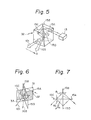
- Figures 5 to 7 show an embodiment of a compact hologram module or hologram unit forming a deflection device according to the present invention, in which a desired number of holograms are integrally incorporated in a transparent polygonal body in the following special arrangement.
- a desired number of holograms are integrally incorporated in a transparent polygonal body in the following special arrangement.
- four plane diffraction holograms 15A -15D are located in a parallelepiped glass body 32 in a diagonal arrangement.
- the laser beam emitted from the tunable laser 13 When the laser beam emitted from the tunable laser 13 is incident at a slant from above upon the glass body 32 at a predetermined angle, the light is successively diffracted downward by the holograms 15A to 15D substantially along an angle spiral path (having one and a half turns in the illustrated embodiment) and finally emitted outward from the final hologram (hologram 15B in the illustrated embodiment).
- the wavelength of the laser beam is varied by the tunable laser 13
- the light emitted from the hologram module can be scanned from point 101 to point 103 in the direction A shown in Fig. 5.
- Fig. 6 which shows only the plane holograms 15A -15D perpendicular to each other, one of the holograms, i.e., the first hologram upon which the light is incident from the tunable laser 13, i.e., the hologram 15A, has a non-hologram portion 31 in which a hologram is not formed: This will be referred to as a beam incident portion.
- the hologram from which the deflected light is emitted e.g., the hologram 15C
- the beam incident portion 31 is formed in an upper edge portion of the hologram 15A and the beam emitting portion 33 is formed in a lower edge portion of the hologram 15C.
- the light incident upon the beam incident portion 31 (non-hologram portion) of the hologram 15A at a slant from above and toward the second hologram 15B through the beam incident portion 31 are first diffracted by the second hologram 15B toward the third hologram 15C at a diffraction angle ⁇ 9i.
- the light is then diffracted by the third hologram 15C toward the fourth hologram 15D at a diffraction angle 0 2 . This diffraction is repeated.
- the light is sent downward substantially along the angled spiral path every time the diffraction occurs.
- the light is emitted outward from the emitting portion 33 (non-hologram portion) of the third hologram 15C after the light has passed through about one and a half turns of the angled spiral.
- the change of the wavelength of the laser beam incident upon the incident portion 31 of the first hologram 15A causes the change in the deflection angle of the plane holograms, to enable a scan of the emitted rays between points 101 and 103.
- the diffraction grating of at least one hologram, e.g., the hologram 15A, at a predetermined inclination angle A 0, from the axis of symmetry (center axis of the four holograms), as shown in Fig. 6.
- the inclined gratings cause the light perpendicularly incident upon the side face of the parallelepiped glass body 32 to be diffracted downward.
- the hologram has an inclined diffraction grating
- the hologram 15B which first diffracts the incident beam
- the hologram 15A is shown with inclined diffraction gratings, this is only for clarification, since the inclination of the diffraction gratings can be seen clearest in the hologram 15A rather than the hologram 15B.
- Figures 8 and 9 show a concrete example of the construction of the hologram module shown in Figs. 5 to 7.
- the hologram module has four rectangular prisms 50 having a height of 20 mm and a side length of 10 mm, and having a right-angle triangular cross section. Two of the prisms 50 have hologram material applied to the adjacent side faces defining a right angle.
- the hologram material can be, for example, PVCz (polyvinyl carbazole), but is not limited thereto.
- One of the two rectangular prisms having the diffraction grating (holograms) 53 has non-hologram portions having a width of 5 mm in the height direction on an upper edge portion of one side face and on a lower edge portion of the other side face, to provide the incident portion 31 and the emitting portion 33 (Fig. 9).
- the two rectangular prisms having holograms formed thereon and opposed to each other, and the remaining two rectangular prisms 50 having no hologram formed thereon and opposed to each other, are bonded together by an adhesive to form a parallelepiped hologram module (assembly) in which the latter two prisms 50 having no hologram are located between the first two prisms 50 having holograms, so that the assembly has a hologram (grating) 53 located in a diagonal arrangement in the parallelepiped transparent body.
- FIG. 10 shows a modified embodiment of Fig. 8.
- each of the rectangular prisms 50 has one hologram (grating) 53 on one of the side faces defining a right angle.
- four identical rectangular prisms 50 having the holograms 53 are bonded together, similar to Fig. 8, to realize a hologram module equivalent to the hologram shown in Fig. 8.
- Laser beams 4 mmo in diameter are incident upon the hologram module shown in Fig. 8.
- the laser beam source is, for example, a tunable semiconductor laser by which the wavelength of 780 nm can be varied within the range of ⁇ 5 nm.
- the light in the glass is diffracted by the first hologram 53.
- the diffraction angle 0 m of the light by the m'th (m-order) hologram is given by the following equation: wherein n is a refractive index.
- exit angle 0 of the light emitted from the emitting portion 33 of the hologram module is given by the following equation, in accordance with Snell's law:
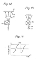
- Figure 12 shows the application of the device of the invention to a known laser printer.
- the beam emitted from the tunable semiconductor laser 13 is scanned along a straight line (scanning line) on a photosensitive recording drum 57 of the laser printer by the hologram module 40 of the present invention, as mentioned above, through a known f 8 lens 55 for focussing the scanning beam, which otherwise would be scanned in an arc as shown at 110 in Fig. 12, onto a plane.
- the subject of the present invention is not directed to the laser printer itself, and accordingly, a detailed explanation of the construction of the laser printer will not be given herein.
- the following equation is obtained from equations @ and 4 :
- Figure 13 shows another embodiment, in which the laser beam light emitted from the tunable semiconductor laser is collimated by a collimate lens 59, so that parallel beams of light are incident upon the hologram module 40.
- the f 0 lens is not provided in this embodiment.
- the beam is actually scanned in an arc, as mentioned before. It is also possible to provide an additional hologram in order to correct the focussing points along the arc, to scan the beam in a straight line. In the arrangement shown in Fig. 13, the last hologram of the hologram module corrects the beam.
- Fig. 12 it is also possible to provide a difference in the variation of the wavelength per unit time, as shown in Fig. 14, i.e., to carry out a timed control of the sweep of the wavelength and thus realize scanning at the same speed.
- the invention can be also applied to a bar-code reader or an optical head, etc.
- Figures 15 to 17 show another embodiment of the present invention, in which a combination of a transmission hologram and reflecting mirrors is used to realize a hologram module of the invention.
- the module essentially has two reflecting surfaces 71, 72 and a transmission hologram 150 located between the reflecting surfaces 71, 72.
- the reflecting surfaces 71 and 72 are embodied by reflecting mirrors formed on adjacent side faces of a rectangular optical glass 74, so that the light entering the hologram module is reflected by the reflecting surfaces.
- the reflecting surface 71 has partial non-reflecting portions 71a and 71b, through which the light is transmitted, so that the incident light can pass through the non-reflecting portion 71a a into the hologram module and the outgoing light can be emitted therefrom through the non-reflecting portion 71 b, which is located lower than the non-reflecting portion 71a, as shown in Fig. 15.
- the reflecting surfaces 71 and 72 intersect each other at a predetermined angle P (e.g. 90°), at an intersecting axis (z-axis).
- P e.g. 90°
- the plate-like hologram 150 is extended so that it intersects the z-axis.
- the hologram 150 has plane gratings with grating grooves parallel to the z-axis. The parallel arrangement of the grating grooves to the z-axis is not always necessary.
- the optical glass 74 which is an optical media, is formed, for example, by BK7.
- the optical medium can be air.
- the reflecting surfaces 71 and 72 can be formed on respective plate-like reflecting mirrors which intersect each other at a predetermined angle P.
- the laser beam (wavelength X) is incident upon the hologram module through the non-reflecting portion 71a a of the reflecting surface 71 from the tunable laser 13, preferably at an incident angle of a with respect to the surface plane thereof, as shown in Fig. 17.
- the incident light is preferably parallel but can be convergent.
- the incident light enters the optical medium (optical glass 74) through the non-reflecting portion 71a a without being reflected.
- the light reaches the hologram 150 and is diffracted thereby toward the reflecting surface 72.
- the light is then reflected again by the reflecting surface 72 toward the hologram 150, so that the light is diffracted by the hologram 150 toward the reflecting surface 71.
- the reflection by the reflecting surfaces 71 and 72 and the diffraction by the hologram 150 are repeated, and finally, the light is emitted from the hologram module through the non-reflecting portion 71 b.
- the solid line shows one example of the beam track and the points represented by 1, 2, 3 and 4 are points on the hologram 150 at which the light is diffracted.
- the points at which the light is diffracted by the hologram 150 are successively moved downward in the order of 1, 2, 3 and 4, as shown in Fig. 17.
- the wavelength is increased by ⁇
- the diffraction angle is increased accordingly, and thus the diffraction angle is successively increased every time the light is diffracted by the hologram.
- the points represented by 1', 2', 3' and 4' are points on the hologram 150 at which the light having a wavelength of ⁇ ' is diffracted.
- the light is finally emitted through the non-reflecting portion 71 b from the hologram module.
- the angle and the position of the light emitted from the hologram module through the non-reflecting portion 71b vary in accordance with the change of the wavelength of the beam, as mentioned above, so that the light can be scanned by a control of the wavelength of the incident beam.
- the hologram 150 is embedded in the glass body (optical glass).
- the hologram is preferably a phase hologram and the material of the hologram can be polyvinyl carbazol or gelatin dichromate, etc.
- the reflecting surface 71 has non-reflecting portions corresponding to the incident portion 71a and outgoing portion 71 b in the direction perpendicular to the z-axis.
- the reflectivity of the reflecting surfaces is more than 99%, which is realized by forming multilayers of film on the reflecting surfaces.
- the light is reflected by the reflecting surface 72 and reaches point 2 of the hologram 150, where the light is similarly diffracted by the hologram 150.
- the light is incident upon reflected by the reflecting surface 72 at an angle of about 0.74°.
- the light incident upon the hologram at an incident angle of ⁇ o is incident again upon the hologram at an incident angle of sin- 1 (cos e o ) after reflection by the associated reflecting surface.
- the change in the angle of the hologram causes a reduction of the incident angle of the subsequent incidence of the light upon the hologram, and accordingly, an increase of the diffraction angle. This results in a synergetic effect of a change of the angle by the hologram and the reduction of the incident angle, resulting in a large change in angle.
- Figure 18 shows one example of a beam track, which can be mathematically obtained, in the present invention.
- the light is subject to repeated diffraction and reflection to cause the change in the outgoing angle and the position thereof.
- Figure 19 shows a relationship between the number of diffractions by the hologram and the change in angle when the wavelength varies by +5 nm and -5 nm, respectively.
- the change in angle referred to means a difference in angle occurring when the wavelength changes and when the wavelength does not change.
- Two change curves are shown in Fig. 19, one for in the air and the other for in the glass.
- the change of +5 nm in the wavelength causes a change of 22.7° in angle in the air
- the change of -5 nm in wavelength causes a change of -7.98° in angle. If eleven diffractions occur, the light is then emitted from the hologram module through a non-reflecting portion which is provided on the reflecting surface 72, similar to the non-reflecting portion 71b of the reflecting surface 71, and the change in angle ( ⁇ ) is 34.0°.
- Figure 20 shows a relationship between the change in angle (A 0) and the change of wavelength (A 0) in the case of eleven diffractions (number N of the diffraction is 11). Note that the change of -5 nm in wavelength causes a -8.3° change in angle. Therefore, a ⁇ 5 nm change in wavelength can produce an about 42° change in angle. This change in angle is sufficient for the application of the hologram module of the present invention, for example, to a laser printer.
- the efficiency ⁇ of light usage is given by the following equation, provided that the efficiency of the hologram is 95% and the reflectivity of the reflecting surfaces is 99%.
- the beam focussing can be achieved by a known additional optical system, such as an optical head in an optical disc apparatus which has a beam converging function and which can be provided at a portion of the hologram module from which the light is emitted, e.g., at the non-reflecting portion 71 b.
- the constant speed beam scanning can be achieved by control of the electric current of the tunable laser which controls the change of the wavelength in relation to time, as mentioned above with reference to Fig. 14.
- Figures 21 and 22 show another application of the present invention, in which more than two tunable lasers (three tunable lasers 13a, 13b, and 13c are shown in the illustrated embodiment) are provided to realize a multi-beam scanner.
- the beams are emitted from three separate tunable lasers and are reflected by respective additional mirrors M toward the non-reflecting portion (incident portion) 71a of the reflecting surface 71.
- the incident angles of the three beams can be either identical to or different from each other.
- the outgoing portion i.e. the exit non-reflecting portion 72b, is formed on the reflecting surface 72 rather than on the reflecting surface 71.
- the three beams are incident upon the incident portion 71a at an incident angle a' with respect to a line normal to the incident surface, along an oblique line, unlike Fig. 21 in which the three beams are incident upon a vertical line.
- the beam deflection is non-mechanically effected.
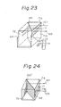
- Figures 23 and 24 show modified embodiments of Figs. 21 and 22.
- the reflecting surface 72 is inclined by ⁇ with respect to a vertical plane, which is perpendicular to a vertical plane including the reflecting surface 71. With this arrangement, it is possible to make the light incident upon the incident portion (non-reflecting portion) 71a normal thereto (i.e.
- the diffraction grating of the hologram 150° is inclined at an angle ⁇ with respect to the vertical, instead of the Inclination of the reflecting surface 72 as shown in Fig. 23.
- the arrangement shown in Fig. 24 is functionally equivalent to the arrangement shown in Fig. 23. Namely, even if the light is Incident upon the incident portion 71a a perpendicularly thereto, the light can be emitted from the hologram module through the lower non-reflecting portion 71b formed on the side face including the reflecting surface 71 or 72.
- numerals 101 and 103 designate incident light and outgoing light, respectively.
- Figures 25A, 25B, 26, and 27 show three modified embodiments in which the most significant feature resides in the use of a reflection hologram instead of the transmission hologram in the above-mentioned embodiments.
- a hologram module has a glass body 63 with a triangular section which is provided, on adjacent side faces defining an angle P which is less than 90° in the illustrated embodiment, with a reflecting surface 71 and a reflection hologram 65.
- the optical medium is air, not glass.
- the side face of the hologram module including the reflecting surface 71 has a partial non-reflecting portion 71a (Figs. 21, 23, 24, etc.) upon which the light 101 is incident.
- the side face including the reflection hologram 65 has a partial non-hologram portion 65b through which the light 103 or 103' is finally emitted, as shown in Fig. 25B.
- the light 101 incident upon the non-reflecting portion (incident portion) from the tunable laser 13 is diffracted by the reflection hologram 65 toward the reflecting surface 71, by which the diffracted light is reflected.
- the light after repeated diffraction by the reflection hologram 65 and repeated reflection by the reflecting surface 71, similar to the foregoing embodiments, is emitted from the hologram module through the non-hologram portion 65b.
- the light is incident upon the incident portion 71 a at a predetermined angle, similar to, for example, Fig. 21.
- the hologram module shown in Figs. 25A and 25B is functionally almost equivalent to the aforementioned embodiments.
- the reflection and diffraction angle increases as the angle P defined by the reflecting surface 71 and the reflection hologram 65 increases.
- n the diffraction index of the optical medium 63 and ⁇ is the wavelength of the beams.
- Numeral 103' designates one example of the light which is finally emitted from the hologram module when the wavelength of the incident beam is changed.
- two reflection holograms 65A and 65B are provided on the adjacent side faces of the glass body 63. Namely, the reflecting surface 71 in Fig. 25A is replaced with the additional reflection hologram 65B in Fig. 26.
- the hologram module shown in Fig. 26 the light 101 from the tunable laser 13 is incident upon the incident portion (non-hologram portion) which corresponds to the incident portion 71 a, for example, in Fig. 21, and which is provided on one of the side faces including the reflection hologram 65B or reflection hologram 65A, at a predetermined incident angle.
- the incident light is repeatedly diffracted and reflected between the two reflection holograms 65A and 65B.
- the light 103 and 103' is emitted from a non-hologram portion which corresponds to the non-hologram portion 65b shown in Fig. 25B and which is provided on the side face including the reflection hologram 65A, similar to the aforementioned embodiments.
- a transmission hologram 150 and reflection holograms 65A and 65B are provided.
- the transmission hologram 150 is located between the opposite side faces of two identical glass bodies having a right angle triangle cross section.
- the reflection holograms 65A and 65B are aligned perpendicularly to the transmission hologram 150.
- the incident portion (non-hologram portion) upon which the light 101 from the tunable laser 13 is incident and the outgoing portion (non-hologram portion) from which the light 103 is finally emitted are both provided on the transmission hologram 150.
- the light can be scanned in accordance with the change in wavelength of the incident beam, similar to the aforementioned embodiments.
- numerals having a prime designate the order of the diffraction and reflection of the incident light in the hologram module.
- Such a hologram having constant pitch gratings and different Bragg angles can be produced in the process as disclosed, for example, in Japanese Unexamined Patent Publication (Kokai) No. 58-158678 corresponding to US Application Serial No. 467.773.
- Figure 28 shows an example of how to produce a hologram used in the present invention, in which a master hologram with 2740/mm 2 of equi-pitch gratings is first formed by interference exposure process of two groups of coherent light (plane waves at 41.9° and -41.9°). Then, a copy hologram plate 201 with a photosensitive layer on which a copy hologram is to be formed is located below the master hologram 200 through an index matching liquid (e.g. xylene or ethyl alcohol, etc.) 203.
- an index matching liquid e.g. xylene or ethyl alcohol, etc.
- the copying light 207 is incident upon the master hologram 200 at different incident angles 0 c (x), which are properly selected to be optimum, depending on the position x of the master hologram 200.
- Such light having different incident angles can be easily created, for example, by a cylindrical lens or the like.
- the angle P in Figs. 15, 25A, and 26 is less than 180°, and preferably less than 90°.
Landscapes
- Physics & Mathematics (AREA)
- General Physics & Mathematics (AREA)
- Optics & Photonics (AREA)
- Holo Graphy (AREA)
- Diffracting Gratings Or Hologram Optical Elements (AREA)
- Mechanical Optical Scanning Systems (AREA)
Applications Claiming Priority (4)
| Application Number | Priority Date | Filing Date | Title |
|---|---|---|---|
| JP21892/87 | 1987-02-03 | ||
| JP62021892A JPH0664255B2 (ja) | 1987-02-03 | 1987-02-03 | ホログラム偏向装置 |
| JP62287561A JPH01129205A (ja) | 1987-11-16 | 1987-11-16 | ホログラム偏向装置 |
| JP287561/87 | 1987-11-16 |
Publications (3)
| Publication Number | Publication Date |
|---|---|
| EP0277883A2 true EP0277883A2 (fr) | 1988-08-10 |
| EP0277883A3 EP0277883A3 (fr) | 1991-01-02 |
| EP0277883B1 EP0277883B1 (fr) | 1996-04-24 |
Family
ID=26359021
Family Applications (1)
| Application Number | Title | Priority Date | Filing Date |
|---|---|---|---|
| EP88400248A Expired - Lifetime EP0277883B1 (fr) | 1987-02-03 | 1988-02-02 | Dispositif de déflexion holographique |
Country Status (4)
| Country | Link |
|---|---|
| US (1) | US4938550A (fr) |
| EP (1) | EP0277883B1 (fr) |
| DE (1) | DE3855226T2 (fr) |
| ES (1) | ES2086303T3 (fr) |
Cited By (2)
| Publication number | Priority date | Publication date | Assignee | Title |
|---|---|---|---|---|
| DE3939551A1 (de) * | 1989-11-30 | 1991-06-06 | Linotype Ag | Optisches positionierungssystem fuer mindestens einen bildpunkt |
| WO2001052369A1 (fr) * | 2000-01-10 | 2001-07-19 | Telefonaktiebolaget Lm Ericsson (Publ) | Dispositif integre de controle des longueurs d'onde |
Families Citing this family (9)
| Publication number | Priority date | Publication date | Assignee | Title |
|---|---|---|---|---|
| GB8904320D0 (en) * | 1989-02-24 | 1989-07-05 | Pilkington Plc | Holographic exposure method and apparatus |
| FR2691549A1 (fr) * | 1992-05-22 | 1993-11-26 | Thomson Csf | Séparateur chromatique de lumière et projecteur d'image utilisant un tel séparateur. |
| US6487016B1 (en) * | 1997-08-26 | 2002-11-26 | Matsushita Electric Industrial Co., Ltd. | Optical head |
| US6057947A (en) * | 1997-12-24 | 2000-05-02 | International Business Machines Corporation | Enhanced raster scanning assembly |
| US6447664B1 (en) * | 1999-01-08 | 2002-09-10 | Scimed Life Systems, Inc. | Methods for coating metallic articles |
| JP2001326290A (ja) * | 2000-03-10 | 2001-11-22 | Seiko Epson Corp | パッケージの封止方法、電子素子モジュールの製造方法、封止装置並びにパッケージ品 |
| US6687036B2 (en) * | 2000-11-03 | 2004-02-03 | Nuonics, Inc. | Multiplexed optical scanner technology |
| US20050083534A1 (en) * | 2003-08-28 | 2005-04-21 | Riza Nabeel A. | Agile high sensitivity optical sensor |
| DE102019200154A1 (de) * | 2019-01-09 | 2020-07-09 | Robert Bosch Gmbh | Sendeeinheit für einen LIDAR-Sensor, LIDAR-Sensor mit einer Sendeeinheit und Verfahren zur Ansteuerung einer Sendeeinheit für einen LIDAR-Sensor |
Family Cites Families (18)
| Publication number | Priority date | Publication date | Assignee | Title |
|---|---|---|---|---|
| US3695744A (en) * | 1971-01-14 | 1972-10-03 | Rca Corp | Holographic multicolor technique |
| US3903483A (en) * | 1974-01-07 | 1975-09-02 | Us Navy | Dye laser for holographic applications |
| NL7606290A (nl) * | 1975-06-25 | 1976-12-28 | Xerox Corp | Laser-aftastsysteem met behulp van door een reken- machine opgewekte hologrammen. |
| US4307929A (en) * | 1979-08-29 | 1981-12-29 | Eveleth Jason H | Method of scanning a laser beam in a straight line |
| US4420218A (en) * | 1980-04-19 | 1983-12-13 | Institut Fiziki An Bssr | Method of object imaging |
| JPS572018A (en) * | 1980-06-06 | 1982-01-07 | Fujitsu Ltd | Light scanner |
| US4378141A (en) * | 1981-04-20 | 1983-03-29 | Yevick George J | Exposure package for holography |
| JPS58158678A (ja) * | 1982-03-16 | 1983-09-20 | Fujitsu Ltd | ホログラムの作成方法 |
| JPS5912416A (ja) * | 1982-07-14 | 1984-01-23 | Ricoh Co Ltd | 多ビ−ム光走査装置 |
| JPS6066337A (ja) * | 1983-09-20 | 1985-04-16 | Sony Corp | フオ−カスサ−ボ装置 |
| US4573758A (en) * | 1984-05-31 | 1986-03-04 | Robotic Vision Systems, Inc. | Beam deflection mechanism |
| JPS60254112A (ja) * | 1984-05-31 | 1985-12-14 | Fujitsu Ltd | 光ビ−ム走査装置 |
| JPS6148813A (ja) * | 1984-08-17 | 1986-03-10 | Yokogawa Hokushin Electric Corp | ホログラムを用いた光走査装置 |
| JPS61134728A (ja) * | 1984-12-06 | 1986-06-21 | Nec Corp | 光走査装置 |
| JPH0610699B2 (ja) * | 1984-12-06 | 1994-02-09 | 日本電気株式会社 | 光走査装置 |
| JPS61202128A (ja) * | 1985-03-06 | 1986-09-06 | Hitachi Ltd | 半導体レ−ザヘテロダイン干渉計 |
| FI74154C (fi) * | 1985-06-20 | 1987-12-10 | Eero Byckling | Foerfarande foer bestrykning av laserstraole medelst icke-mekaniska avlaenkningsdon. |
| KR910002322B1 (ko) * | 1986-09-20 | 1991-04-11 | 후지쓰 가부시끼가이샤 | 회절격자렌즈 조립체를 구비하고 있는 광학시스템 |
-
1988
- 1988-02-02 ES ES88400248T patent/ES2086303T3/es not_active Expired - Lifetime
- 1988-02-02 EP EP88400248A patent/EP0277883B1/fr not_active Expired - Lifetime
- 1988-02-02 DE DE3855226T patent/DE3855226T2/de not_active Expired - Fee Related
- 1988-02-02 US US07/151,616 patent/US4938550A/en not_active Expired - Lifetime
Cited By (7)
| Publication number | Priority date | Publication date | Assignee | Title |
|---|---|---|---|---|
| DE3939551A1 (de) * | 1989-11-30 | 1991-06-06 | Linotype Ag | Optisches positionierungssystem fuer mindestens einen bildpunkt |
| WO1991008504A1 (fr) * | 1989-11-30 | 1991-06-13 | Linotype-Hell Ag | Systeme de positionnement optique d'au moins un point d'image |
| US5387995A (en) * | 1989-11-30 | 1995-02-07 | Linotype-Hell Ag Corporation | Optical positioning system for at least one picture element |
| US5570223A (en) * | 1989-11-30 | 1996-10-29 | Linotype-Hell Ag | Optical positioning system for at least one picture element |
| US5661586A (en) * | 1989-11-30 | 1997-08-26 | Linotype-Hell Ag | Optical positioning system for at least one picture element |
| WO2001052369A1 (fr) * | 2000-01-10 | 2001-07-19 | Telefonaktiebolaget Lm Ericsson (Publ) | Dispositif integre de controle des longueurs d'onde |
| US6639679B2 (en) | 2000-01-10 | 2003-10-28 | Telefonaktiebolaget L M Ericsson (Publ) | Integrated wavelength monitor |
Also Published As
| Publication number | Publication date |
|---|---|
| EP0277883A3 (fr) | 1991-01-02 |
| DE3855226T2 (de) | 1996-09-05 |
| EP0277883B1 (fr) | 1996-04-24 |
| US4938550A (en) | 1990-07-03 |
| ES2086303T3 (es) | 1996-07-01 |
| DE3855226D1 (de) | 1996-05-30 |
Similar Documents
| Publication | Publication Date | Title |
|---|---|---|
| US4390235A (en) | Multibeam scanning apparatus provided with a function of changing magnification | |
| US5986778A (en) | Hologon deflector system having dispersive optical elements for scan line bow correction, wavelength shift correction and scanning spot ellipticity correction | |
| US4904034A (en) | Scanning apparatus | |
| EP1291690B1 (fr) | Commutateur optique avec élément convergent | |
| US4923262A (en) | Scanner system having rotating deflector hologram | |
| EP0028160B1 (fr) | Systèmes de balayage optique à spot volant | |
| US4123135A (en) | Optical system for rotating mirror line scanning apparatus | |
| US3972582A (en) | Laser beam recording system | |
| US4756585A (en) | Optical beam scanning system | |
| EP0281756B1 (fr) | Miroir holographique d'objectif pour mémoire optique | |
| US4938550A (en) | Holographic deflection device | |
| US6771421B2 (en) | Beam pattern contractor and focus element, method and apparatus | |
| EP0526846A2 (fr) | Appareil de balayage optique à plusieurs faisceaux | |
| US5365259A (en) | Scanning optical device | |
| EP0571364B1 (fr) | Dispositif de balayage a laser holographique | |
| US4626062A (en) | Light beam scanning apparatus | |
| JPH0153767B2 (fr) | ||
| US5438450A (en) | Optical scanning apparatus | |
| EP0078269A4 (fr) | Dispsotif de balayage a grille de difraction avec correction anamorphe des courbures de balayage. | |
| US4848863A (en) | Multi-wavelength scanning system | |
| JPH0820621B2 (ja) | プリンタ用放射源 | |
| JP2952237B2 (ja) | ビーム走査装置 | |
| JP2706984B2 (ja) | 走査光学装置 | |
| US4632499A (en) | Light beam scanning apparatus | |
| JPH0588100A (ja) | 走査装置 |
Legal Events
| Date | Code | Title | Description |
|---|---|---|---|
| PUAI | Public reference made under article 153(3) epc to a published international application that has entered the european phase |
Free format text: ORIGINAL CODE: 0009012 |
|
| AK | Designated contracting states |
Kind code of ref document: A2 Designated state(s): DE ES FR GB |
|
| PUAL | Search report despatched |
Free format text: ORIGINAL CODE: 0009013 |
|
| AK | Designated contracting states |
Kind code of ref document: A3 Designated state(s): DE ES FR GB |
|
| 17P | Request for examination filed |
Effective date: 19901224 |
|
| 17Q | First examination report despatched |
Effective date: 19921005 |
|
| GRAH | Despatch of communication of intention to grant a patent |
Free format text: ORIGINAL CODE: EPIDOS IGRA |
|
| GRAA | (expected) grant |
Free format text: ORIGINAL CODE: 0009210 |
|
| AK | Designated contracting states |
Kind code of ref document: B1 Designated state(s): DE ES FR GB |
|
| REF | Corresponds to: |
Ref document number: 3855226 Country of ref document: DE Date of ref document: 19960530 |
|
| REG | Reference to a national code |
Ref country code: ES Ref legal event code: FG2A Ref document number: 2086303 Country of ref document: ES Kind code of ref document: T3 |
|
| ET | Fr: translation filed | ||
| PLBE | No opposition filed within time limit |
Free format text: ORIGINAL CODE: 0009261 |
|
| STAA | Information on the status of an ep patent application or granted ep patent |
Free format text: STATUS: NO OPPOSITION FILED WITHIN TIME LIMIT |
|
| 26N | No opposition filed | ||
| PGFP | Annual fee paid to national office [announced via postgrant information from national office to epo] |
Ref country code: DE Payment date: 20010129 Year of fee payment: 14 |
|
| PGFP | Annual fee paid to national office [announced via postgrant information from national office to epo] |
Ref country code: GB Payment date: 20010131 Year of fee payment: 14 |
|
| PGFP | Annual fee paid to national office [announced via postgrant information from national office to epo] |
Ref country code: FR Payment date: 20010213 Year of fee payment: 14 |
|
| PGFP | Annual fee paid to national office [announced via postgrant information from national office to epo] |
Ref country code: ES Payment date: 20010214 Year of fee payment: 14 |
|
| REG | Reference to a national code |
Ref country code: GB Ref legal event code: IF02 |
|
| PG25 | Lapsed in a contracting state [announced via postgrant information from national office to epo] |
Ref country code: GB Free format text: LAPSE BECAUSE OF NON-PAYMENT OF DUE FEES Effective date: 20020202 |
|
| PG25 | Lapsed in a contracting state [announced via postgrant information from national office to epo] |
Ref country code: ES Free format text: LAPSE BECAUSE OF NON-PAYMENT OF DUE FEES Effective date: 20020204 |
|
| PG25 | Lapsed in a contracting state [announced via postgrant information from national office to epo] |
Ref country code: DE Free format text: LAPSE BECAUSE OF NON-PAYMENT OF DUE FEES Effective date: 20020903 |
|
| GBPC | Gb: european patent ceased through non-payment of renewal fee |
Effective date: 20020202 |
|
| PG25 | Lapsed in a contracting state [announced via postgrant information from national office to epo] |
Ref country code: FR Free format text: LAPSE BECAUSE OF NON-PAYMENT OF DUE FEES Effective date: 20021031 |
|
| REG | Reference to a national code |
Ref country code: FR Ref legal event code: ST |
|
| REG | Reference to a national code |
Ref country code: ES Ref legal event code: FD2A Effective date: 20030922 |